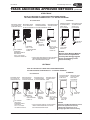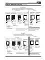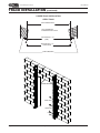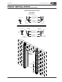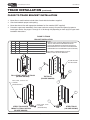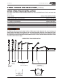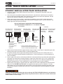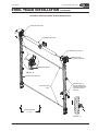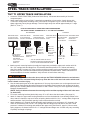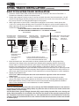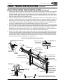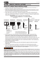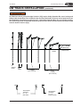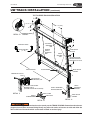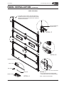
1
TKO
WELTERWEIGHT
®
DOCK DOOR
User’s Manual - Installation, Operations, Maintenance and Parts Listing
This manual applies to WelterWeight Dock Doors manufactured beginning
May 2012
DO NOT install, operate or service this product unless you have read and understand the safety
practices, warnings, installation and operation instructions contained in this manual. Failure to do so
could result in death or serious injury.
© 2012 4Front Engineered Solutions, Inc.
15-00015 R10 05/12 WW
TKO WelterWeight Dock Doors
User’s Manual
TABLE OF CONTENTS
LIMITED WARRANTY
1
OWNER’S RESPONSIBILITIES
2
TOOLS & MATERIALS
3
Recommended Anchor System for Hollow Block
3
SAFETY
4
Safety Signal Words
Safety Practices
4
4
SITE PREPARATION
6
Door Opening
Track Mounting Surface
6
8
TRACK ANCHORING APPROVED METHODS
10
Structure
10
TRACK INSTALLATION
12
Lower Track Installation
12
STEEL TRACK INSTALLATION
17
Straight Vertical Upper Track Installation
Tilt T1 Upper Track Installation
Tilt T2 Upper Track Installation
Roof Pitch Upper Track Installation
High-Lift Upper Track Installation
18
20
24
28
30
UW TRACK INSTALLATION
32
Straight Vertical Upper Track Installation
Tilt T1 Upper Track Installation
Tilt T2 Upper Track Installation
Roof Pitch Upper Track Installation
High-Lift Upper Track Installation
34
36
40
44
46
PANEL INSTALLATION
48
Component Identification
Panel Stacking
Slide Lock Installation
Lintel Seal Installation
48
50
52
52
Decals & Placard Installation
53
SPRING/SHAFT INSTALLATION
56
Center Spring Pad Installation
Component Identification
Single Spring/Single Shaft Assembly
Double Spring/Single Shaft Assembly
Double Spring/Split Shaft Assembly
56
58
58
60
62
Page
ii
© 2012 4Front Engineered Solutions, Inc.
15-00015 R10 05/12 WW
User’s Manual
TKO WelterWeight Dock Doors
TABLE OF CONTENTS
(continued)
WINDING SPRINGS
64
Secure Door
Install Cables
Wind Springs
64
64
64
DOOR OPERATION
68
AVAILABLE OPTIONS
69
PLANNED MAINTENANCE
70
TROUBLE SHOOTING
71
PARTS LISTING
72
15-00015 R10 05/12 WW
© 2012 4Front Engineered Solutions, Inc.
Page
iii
TKO WelterWeight Dock Doors
User’s Manual
NOTES
Page
iv
© 2012 4Front Engineered Solutions, Inc.
15-00015 R10 05/12 WW
User’s Manual
TKO WelterWeight Dock Doors
LIMITED WARRANTY
THIS LIMITED WARRANTY IS TKO DOCK DOORS SOLE AND EXCLUSIVE WARRANTY WITH RESPECT
TO THE DOCK DOOR AND IS IN LIEU OF ANY OTHER GUARANTEES OR WARRANTIES, EXPRESS OR
IMPLIED.
aws in material and workmanship
under normal use for a period of ONE (1) year from the earlier of 1) 60 days after the date of initial shipment
by TKO DOCK DOORS, or 2) the date of installation of the DOCK DOOR by the original purchaser, provided
that the owner maintains and operates the DOCK DOOR in accordance with this User’s Manual.
TKO DOCK DOORS warrants its WelterWeight Panels will remain operational after resetting from impact
under normal use, service and maintenance for ONE (1) year (excluding any window portion thereof) from
date of shipment. Does not cover punctures, cracks or slices in panel(s). Optional Super Panel: TWO (2) year
performance limited warranty from date of shipment.
EXTENDED LIMITED WARRANTY
TKO DOCK DOORS warrants its optional “Impact-A-Track” for FIVE (5) years from date of purchase. This
is a performance warranty and for the UHMW portion only. Cuts, gouges, and abrasions are not considered
warrantable conditions.
In the event that this DOCK DOOR proves deficient in material or workmanship within the applicable limited
warranty period, TKO DOCK DOORS will, at its option:
1. Replace the DOCK DOOR, or the deficient portion of either, without charge to the owner; or
2. Alter or repair the DOCK DOOR on site or elsewhere, without charge to the owner.
This limited warranty does not cover any failure caused by improper installation, abuse, negligence, or failure to
maintain and adjust the DOCK DOOR properly. Parts requiring replacement due to damage resulting from abuse
or improper operation are not covered by this warranty. This limited warranty does not include normal wear,
modifications, and damage beyond the manufacturer’s control, replacement labor or implied cycle life of
counter balance system (cables, spring assemblies, drums, shaft cones and bearings, or center bearing brackets).
TKO DOCK DOORS DISCLAIMS ANY RESPONSIBILITY OR LIABILITY FOR ANY LOSS OR DAMAGE OF
ANY KIND (INCLUDING WITHOUT LIMITATION, DIRECT, CONSEQUENTIAL OR PUNITIVE DAMAGES,
OR LOST PROFITS OR LOST PRODUCTION) arising out of or related to the use, installation or maintenance of
the DOCK DOOR (including premature product wear, product failure, property damage or bodily injury resulting
from use of unauthorized replacement parts or modification of the DOCK DOOR). TKO DOCK DOORS’s sole
obligation with regard to a DOCK DOOR that is claimed to be deficient in material or workmanship shall be as set
forth in this Limited Warranty. This Limited Warranty will be null and void if the original purchaser does not notify
TKO DOCK DOORS’s warranty department within ninety (90) days after the product deficiency is discovered.
THERE ARE NO WARRANTIES, EXPRESS OR IMPLIED, WHICH EXTEND BEYOND THE DESCRIPTION
ON THE FACE HEREOF, INCLUDING, BUT NOT LIMITED TO, A WARRANTY OF MERCHANTABILITY OR
OF FITNESS FOR A PARTICULAR PURPOSE, ALL OF WHICH TKO DOCK DOORS HEREBY DISCLAIMS.
For questions regarding this warranty, services, or parts contact: TKO Customer Service at 1-800-575-3366.
15-00015 R10 05/12 WW
© 2012 4Front Engineered Solutions, Inc.
Page
1
TKO WelterWeight Dock Doors
User’s Manual
OWNER’S RESPONSIBILITIES
THE OWNER’S RESPONSIBILITIES INCLUDE THE FOLLOWING:
z
The owners should recognize the inherent danger of the interface between the dock and transport
vehicle. The owner should, therefore, train and instruct operators in the safe use of the TKO Dock Door
as well as all dock equipment devices.
z
Nameplates, cautions, instructions and posted warnings shall not be obscured from the view of operating
or maintenance personnel for whom such warnings are intended.
z
Manufacturer’s recommended periodic maintenance and inspection (procedures in effect at date of
shipment) shall be followed, and written records of the performance of these procedures should be kept.
z
Loading dock doors that are structurally damaged or have experienced failure shall be removed from
service, inspected by the manufacturer’s authorized representative and repaired as needed before being
placed back in service.
z
The owner shall see that all nameplates, caution and instruction markings or labels are in place and
legible and that the appropriate operating and maintenance manuals are provided to users.
z
Modifications or alterations of loading dock doors shall be made ONLY with the written permission of the
original manufacturer.
z
When industrial trucks are driven on and off transport vehicles during the loading and unloading
operation, the brakes on the transport vehicle shall be applied and wheel chocks or positive restraints
that provide the equivalent protection of wheel chocks engaged.
DO NOT install, operate, or service this product unless you have read and understand the safety
practices, warnings, installation and operation instructions contained in this manual. Failure to do so
could result in death or serious injury.
Page
2
© 2012 4Front Engineered Solutions, Inc.
15-00015 R10 05/12 WW
User’s Manual
TKO WelterWeight Dock Doors
TOOLS & MATERIALS
THE FOLLOWING TOOLS & MATERIALS ARE NECESSARY FOR PROPER INSTALLATION OF ANY TKO
DOOR(S) AND ARE NOT PROVIDED BY TKO:
z
Two Spring Winding Bars, approximately 24” (minimum) long for winding springs.
- 1/2” diameter bars for 2-5/8” diameter springs.
- 5/8” diameter bars for 3-3/4” and 6” diameter springs.
z
Tools to mount track to wall using any of the recommend track anchoring methods:
- Hammer Drill or Impact Wrench.
z
Tools to mount track to wall using any of the alternate track anchoring methods:
- Hammer Drill or Impact Wrench.
- Welder with welding rods. Include grinder if door to be removed is welded to jambs.
z
Aerial equipment: Ladders, scaffolding, scissors lift or boom lift.
z
Hand tools: socket wrench set: 7/16”, 1/2”, 9/16”, 4’ long level, bar clamps or C-clamps, locking pliers/
vice grips, hammer, screwdrivers, and tape measure (contractor grade).
z
Lubricants: Light Weight Oil for lubing Plunger Spring Shafts and Bearings,Torsion/Counterbalance
Springs. Dry Silicone Spray for lubing tracks and side seals.
z
Steel angle (minimum 12 gauge) for Backhangs and Sway Braces. Size will vary with different
applications.
z
Anchors/Fasteners used to mount tracks, center and end bearing plates, etc.
z
Spring Mounting Pad(s) MUST BE structurally sound to support weight of Spring(s) and the torque put
on them.
TKO Dock Doors DOES NOT supply Backhang Material, Spring Mounting Pads or
Wall Mounting Hardware.
RECOMMENDED ANCHORS FOR HOLLOW BLOCK WALL
TKO recommends the following :
•
3/8”-16 Concrete Single or Double Expansion Shield Anchors.
•
3/8” Short Lag Shields.
•
NOTE: Anchors must be those suitable per the manufacturer for use in hollow block wall, and installed per
the manufacturer’s instructions.
15-00015 R10 05/12 WW
© 2012 4Front Engineered Solutions, Inc.
Page
3
TKO WelterWeight Dock Doors
User’s Manual
SAFETY
SAFETY SIGNAL WORDS
You may find safety signal words such as DANGER, WARNING, or CAUTION throughout this owner’s manual.
Their use is explained below.
This is the safety alert symbol. It is used to alert you to potential personal injury hazards. Obey
all safety messages that follow this symbol to avoid possible death or injury.
Indicates an imminently hazardous situation which if not avoided, will result in death or serious injury.
Indicates a potentially hazardous situation which, if not avoided, could result in death or serious injury.
Indicates a potentially hazardous situation which, if not avoided, could result in minor or moderate injury.
Caution used without the safety alert symbol indicates a potentially hazardous situation which, if not
avoided, could result in property damage.
SAFETY PRACTICES
Read and follow these Safety Practices before installing, operating or servicing the door. Failure to
follow the Safety Practices could result in death or serious injury.
If you do not understand the instructions, ask your supervisor to explain them to you, or call TKO at 1-800-5753366, or ask qualified TKO door technician to assist.
Installation, Maintenance and Service
1. ONLY experienced and qualified door technicians should install or repair doors. Springs, cable brackets,
cables, drums, plungers, supports and their hardware are under high tension and can cause injuries if
not properly handled.
2. Use the proper type and capacity ladders, lifting equipment and safety straps or harnesses.
3. Safe and efficient installation requires a two-person crew.
4. Observe OSHA requirements for “LOCKOUT” or “TAGOUT” when performing work on doors.
5. Observe any/all overhead hazards such as electrical, air, process piping or HVAC ducting when working.
6. Move any dock leveler to the dock level storage position before using as a platform for ladders, lift trucks
or other equipment used in the installation of the door.
7. Place barricades on the dock floor around the dock door and in the driveway in front of the door while
installing, maintaining, or repairing the dock door.
8. If door is operated with any type of motor or automatic system, TKO highly recommends the use of a
UL325 compliant entrapment protection device such as monitored safety edge or monitored photoeye.
9. Follow all local and state codes regarding attachment of back-hang to structural components of the
building.
Page
4
© 2012 4Front Engineered Solutions, Inc.
15-00015 R10 05/12 WW
User’s Manual
SAFETY
TKO WelterWeight Dock Doors
(continued)
SAFETY PRACTICES
(continued)
Operation
1. Personnel using the dock doors MUST BE properly trained.
2. Operate door ONLY when properly adjusted and free of obstructions. Should the door become difficult to
operate or completely inoperative, immediately report to supervisor.
3. DO NOT stand or walk under moving door. Keep door in full view and free of obstructions while
operating.
4. DO NOT allow children to operate the door or controls.
5. DO NOT throw door up violently. Using excessive force to open or close the door may cause the door
cables to jump or door panels to disengage from tracks.
6. DO NOT close door onto obstructions. Obstructions in the opening may stop the doors movement and
cause the door cables to jump or door panels to disengage from tracks.
7. To avoid injury, keep hands free of door parts while operating. Panels and door parts may create pinch
points when in operation.
8. NEVER use damaged or malfunctioning dock door.
Resetting Impacted Panels
In the event of a panel KNOCK-OUT or track impact situation, step away from the door a
safe distance.
7. Inspect the door system BEFORE resetting panels.
- Plungers on the top panel MUST BE engaged in track.
- Cables MUST BE properly tensioned and seated in the grooves of the cable drums.
- Panels MUST BE sitting level with hardware intact.
- Tracks MUST BE square to jamb face and securely mounted.
If the above conditions are met, continue with resetting door (see steps 3-6 below). If any of these
conditions are not met, DO NOT use door. Stay clear of door and immediately report incident to
supervisor and have a trained door systems technician inspect and reset door.
8. Clear fork truck and/or all products from dock door area.
9. Grab manufacturer-supplied handle(s) and pull door panels back into tracks. If the spring plunger tips
are obstructed at any point of the return travel, the plunger rods may be manually retracted while pulling
panels back into tracks. Depending on conditions, this operation may require 2 people to safely reset the
door.
- NEVER try to open or close door until all panel plungers are reset back into track
and door has been inspected.
- NEVER climb under impacted panels to reset door.
10. Check panels, track, hardware and fasteners for any damage, looseness, misalignment, and verify track
spacing BEFORE operating door.
11. After panels have been engaged back into the tracks, carefully cycle the door to its fully open and closed
position several times making sure operation is smooth throughout its entire travel cycle.
All TKO Dock Doors [except Straight Verticals (SV)] require Safety Spreader Bar cross bracing and
Safety Cable Assemblies to be installed in the area from the header to the top end of panel travel per
the installation instructions on pages 20 through 31 or 38 through 49 depending on track style. If the
Spreader Bars are not installed, the Tracks may spread, if impacted, and allow the door to fall. Failure
to follow these instructions could result in death or serious injury.
15-00015 R10 05/12 WW
© 2012 4Front Engineered Solutions, Inc.
Page
5
TKO WelterWeight Dock Doors
User’s Manual
SITE PREPARATION
Before installing the door, read and follow the Safety Practices on pages 4 and 5. Failure to follow the
Safety Practices could result in death or serious injury.
DOOR OPENING
1. For the TKO Knock-out Dock Door system to function properly, the door opening MUST BE ‘true’,
‘square’, ‘plumb’ and ‘flush’. Any compromise of the door opening characteristics may affect the function
and performance of the door. If jamb repair, replacement or adjustment is required, it is critical that the
original door opening dimensions are maintained as listed in the original door specification sheet.
2. Measure DOOR OPENING WIDTH (DOW). The finished DOW MUST match the designed TRACK
SPACING dimension as shown on the third panel. The door panels will not easily break away and reset
properly when impacted, or the door panels may fall out of the tracks if the track spacing is not kept
within +/- 1/4” of designed track spacing. Measure width at floor, mid jamb, and header to identify and
correct any width variations.
3. Measure DOOR OPENING HEIGHT (DOH). Verify finished DOH matches the door height listed on the
door spec sheet. Stacked door panels are designed for additional panel height above header for proper
sealing. If the finished DOH exceeds the specified door height more than (3”), contact TKO Doors for
assistance.
4. Check jambs with a level to ensure the jambs are square to door opening. Correct any jamb condition
that will not allow the panels to break out properly.
5. Check jambs with a level to ensure the jambs are plumb and straight. The tracks MUST BE installed
level while maintaining the specified track spacing. If the jambs are not level and straight, a portion of the
jamb may be exposed (in relation to the track), restricting the panels from properly knocking-out.
6. Inspect jamb walls for any obstructions. Ensure that nothing will impede the door’s outward movement
when impacted. Any sharp edges MUST BE eliminated to prevent possible seal damage as panels swing
into the opening when impacted.
7. TKO recommends the easy to install optional 3’, 6’ or Full Height Impact-A-TrackTM to protect portion
of the steel track from being damaged due to impacts. If the optional Impact-A-Track is not used, TKO
recommends the use of pipe bollards for protection of the door tracks.
Contact TKO Doors for assistance at 1-800-575-3366.
Page
6
© 2012 4Front Engineered Solutions, Inc.
15-00015 R10 05/12 WW
User’s Manual
TKO WelterWeight Dock Doors
SITE PREPARATION
(continued)
DOOR OPENING
12”
MAX
MIN 3”
MIN 3”
CENTER BRG ANCHOR PAD
MOUNTING AREAS
[MIN SIZE 2”W X 6”H]
SPLIT SHAFT*
COUNTERWEIGHT BRG
ANCHOR PAD LH &/OR RH
MOUNTING AREAS
[MIN SIZE 2”W X 6”H]
OPERATOR
MTG AREA LH OR RH
(SEE OPERATOR MANUAL
FOR MTG SIZE & LOCATIONS)
SINGLE
SHAFT
MIN 3”
MAX 6”
CL
1/2 DOOR
OPENING
WIDTH
TRACK
MOUNTING
SURFACE
HEADER
TRACK
MOUNTING
HEIGHT
(TMH)
CENTER
LINE OF
SHAFT
(CL)
DOOR
OPENING
HEIGHT
(DOH)
DEPTH INTO
BUILDING
(WTC)
BRUSH SEAL
JAMB WALL
TRACK MTG
WIDTH (TMW)
TRACK
MTG
DEPTH
(TMD)
DOOR
OPENING
WIDTH
(DOW)
* OR 6” DUAL SPRING SINGLE SHAFT
15-00015 R10 05/12 WW
© 2012 4Front Engineered Solutions, Inc.
Page
7
TKO WelterWeight Dock Doors
User’s Manual
SITE PREPARATION
(continued)
TRACK MOUNTING SURFACE
1. Measure available TRACK MOUNTING HEIGHT (TMH). Verify that the required TMH will fit in the
available space. See job specific documents shipped with your order. If the required TMH exceeded
what is available, contact TKO Doors for assistance.
2. Check door specification sheet for track mounting style and track print for TRACK MOUNTING WIDTH
(TMW). Verify that the width of the mounting surface on jamb is equal or greater than the mounting width
of the track.
3. Check TRACK MOUNTING DEPTH (TMD) for any obstructions such as a bollard or curb that would
interfere with mounting the track to the jamb. Verify track depth on track print for track dimension. If track
depth exceeds available space, contact TKO Doors for assistance.
4. Make sure all track-mounting surfaces, header beam and center bearing bracket pads are flush in
relation to one another. The tracks, header seal, and center bearing bracket(s) are designed to be
installed on the same plane. Adjustment of end bearing plates will be necessary to keep upper tracks on
the same plane as lower tracks. All mounting surfaces MUST BE smooth and free of any weld beads or
bolt heads etc.
5. Check available DEPTH INTO BUILDING (WTC) and verify that the upper track assembly will fit within
the given space. Refer to the track print for required track depth.
6. Check for potential obstructions that may impede the door’s normal upward and downward travel such
as an electrical box, sprinkler head, pipe etc. If track adjustment or modification is necessary, please
contact TKO DOORS for assistance.
7. Check that the floor mounting area is level from right to left side within 1/4”. Be prepared to shim under
one side of track if necessary.
Page
8
© 2012 4Front Engineered Solutions, Inc.
15-00015 R10 05/12 WW
User’s Manual
TKO WelterWeight Dock Doors
SITE PREPARATION
(continued)
TRACK MOUNTING SURFACE
12”
MAX
MIN 3”
MIN 3”
CENTER BRG ANCHOR PAD
MOUNTING AREAS
[MIN SIZE 2”W X 6”H]
SPLIT SHAFT*
COUNTERWEIGHT BRG
ANCHOR PAD LH &/OR RH
MOUNTING AREAS
[MIN SIZE 2”W X 6”H]
OPERATOR
MTG AREA LH OR RH
(SEE OPERATOR MANUAL
FOR MTG SIZE & LOCATIONS)
SINGLE
SHAFT
MIN 3”
MAX 6”
CL
1/2 DOOR
OPENING
WIDTH
TRACK
MOUNTING
SURFACE
HEADER
TRACK
MOUNTING
HEIGHT
(TMH)
CENTER
LINE OF
SHAFT
(CL)
DOOR
OPENING
HEIGHT
(DOH)
DEPTH INTO
BUILDING
(WTC)
BRUSH SEAL
JAMB WALL
TRACK MTG
WIDTH (TMW)
TRACK
MTG
DEPTH
(TMD)
DOOR
OPENING
WIDTH
(DOW)
* OR 6” DUAL SPRING SINGLE SHAFT
15-00015 R10 05/12 WW
© 2012 4Front Engineered Solutions, Inc.
Page
9
TKO WelterWeight Dock Doors
User’s Manual
TRACK ANCHORING APPROVED METHODS
STRUCTURE
1. All anchors/fasteners shall be 3/8” DIA and placed in the second from the bottom anchor hole of the
track and then at 18 inch intervals (or every 3rd hole). Please, refer to the Guide on pg. 11 for
specic applications and instructions.
Welding of tracks is listed as Alternate Anchoring Method, however this method will not allow for any
track width adjustments. For this reason TKO recommends the use of self-tapping screws to fasten
tracks to metal surfaces instead.
2. Anchors/fasteners MUST BE centered in the slotted track holes to provide the ability to adjust in or out if
necessary (an extended bit is recommended).
3. If mounting the track to wood it is not recommended that the tracks be mounted solely to a single 2” x 4”,
2” x 6”, 2” x etc. wood face jamb. Anchor/fasten through wood jamb and into structural member using a
minimum 3/8” x 3” anchor backed with a 3/8” flat washer. Fasteners must be appropriate for the material
of the structural member.
4. If mounting the track to steel, position welds or anchors as listed in item 1 above.
5. If mounting the track to solid concrete, anchor tracks using a minimum 3/8” x 1-7/8” concrete sleeve
anchor backed with a 3/8” flat washer. If a wood face jamb exists, anchor through wood jamb and into
concrete structure. Follow manufacturer’s recommendations for installation.
6. If mounting to hollow block, it is important to use 3/8” expansion type anchors specifically designed for
this use. Follow manufacturer’s recommendations for installation.
Failure to securely position and anchor door tracks per the TRACK SPACING dimension and tolerance
(engraved on the door mounted Safety Decal) may allow the tracks to spread and allow the door to fall
out of its tracks which could result in death or serious injury.
Page
10
© 2012 4Front Engineered Solutions, Inc.
15-00015 R10 05/12 WW
User’s Manual
TKO WelterWeight Dock Doors
TRACK ANCHORING APPROVED METHODS
(continued)
STEEL TRACK
NOTE: ALL METHODS OF LOWER TRACK ANCHORING REQUIRE
THE TRACK SPACING TOLERANCES OF +/- 1/4” ARE NOT EXCEEDED.
RECOMMENDED
MOUNTING TRACK
TO C-90 HOLLOW
CONCRETE BLOCK
ALTERNATE
MOUNTING TRACK
MOUNTING TRACK
MOUNTING TRACK
TO FILLED BLOCK
TO WOOD BACKED
TO STRUCTURAL
OR SOLID CONCRETE BY A SOLID MATERIAL STEEL
3/8” FLAT
WASHER
3/8” FLAT
WASHER
3/8” FLAT
WASHER
3/8”-16 SINGLE
OR DOUBLE
EXPANSION SHIELD
ANCHOR OR
3/8“ X 1-3/4” SHORT
LAG SHIELD EVERY 18”
MINIMUM
3/8” X 1-7/8”
SLEEVE ANCHOR
EVERY 18”
3/8” X 3”
ANCHOR*
EVERY 18”
MOUNTING TRACK
TO STRUCTURAL
STEEL WITH
FILLET WELDS
MOUNTING TRACK
TO STRUCTURAL
STEEL WITH
PLUG WELDS
3/8” FLAT
WASHER
3/8” X 1-1/2”
SELF-TAPPING
SCREWS
EVERY 18”
PLUG WELD
EVERY 18”
1/8” FILLET
1-1/2” LONG
EVERY 18”
NOTICE:
Alternate Track Mounting Methods
will not allow track adjustment if
*: TYPE OF ANCHOR USED WILL BE OF SUITABLE necessary.TKO strongly suggests
the use of self-tapping screws
LENGTH AND APPROPRIATE FOR TYPE OF
SOLID BACKING BEHIND WOOD.
instead of welding.
UW TRACK
NOTE: ALL METHODS OF LOWER TRACK ANCHORING REQUIRE
THE TRACK SPACING TOLERANCES OF +/- 1/4” ARE NOT EXCEEDED.
ALTERNATE
RECOMMENDED
MOUNTING TRACK
TO C-90 HOLLOW
CONCRETE BLOCK
MOUNTING TRACK
TO FILLED BLOCK
OR SOLID CONCRETE
3/8” FLAT
WASHER
MOUNTING TRACK
MOUNTING TRACK
TO WOOD BACKED
TO STRUCTURAL
BY A SOLID MATERIAL STEEL
3/8” FLAT
WASHER
MINIMUM
3/8” X 1-7/8”
SLEEVE ANCHOR
EVERY 18”
3/8-16 SINGLE
OR DOUBLE
EXPANSION SHIELD
ANCHOR OR
3/8” X 1-3/4” SHORT
LAG SHIELD EVERY 18”
15-00015 R10 05/12 WW
3/8” FLAT
WASHER
3/8” FLAT
WASHER
3/8” X 3”
ANCHOR*
EVERY 18”
3/8” X 1-1/2”
SELF-TAPPING
SCREWS
EVERY 18”
*: TYPE OF ANCHOR USED WILL BE OF SUITABLE
LENGTH AND APPROPRIATE FOR TYPE OF
SOLID BACKING BEHIND WOOD.
© 2012 4Front Engineered Solutions, Inc.
MOUNTING TRACK
TO STRUCTURAL
STEEL WITH
FILLET WELDS
MOUNTING TRACK
TO STRUCTURAL
STEEL WITH
PLUG WELDS
PLUG WELD
EVERY 18”
1/8” FILLET
1-1/2“ LONG
EVERY 18”
NOTICE:
Alternate Track Mounting Methods will not
allow track adjustment if necessary.
TKO strongly suggests the use of
self-tapping screws instead of welding.
Page
11
TKO WelterWeight Dock Doors
User’s Manual
TRACK INSTALLATION
LOWER TRACK INSTALLATION
1. Locate the TRACK PRINT PDS (Production Detail Sheet). It illustrates the assembly of the track
component parts.
2. Measure finished jamb opening width. The actual jamb width must match with the panel width inscriped
on the door. Call TKO if door width does not match the opening width.
3. Inspect track pieces and line up so that they match job specific track drawing that was supplied with
door. If track drawing is missing, call a TKO Doors customer service representative for assistance.
Check the floor pad for level. Tops of tracks MUST BE level with one another to within 1/4”, or door will
not operate smoothly. Shimming of tracks off the floor may be necessary.
4. While holding the lower left hand (LH) track against the jamb and flush to the opening, carefully level
it. Use approved fastening method (pg.13) on bottom and top holes in track. Anchors/bolts should be
placed in the middle of the sloted holes so tracks can be adjusted later if necessary. If track is to be
welded in place, lightly tack the bottom and top only. Do not fill fasteners/ welds until you are certain the
correct track spacing has been maintained.
5. The track spacing tool can now be used to set the right hand (RH) track. While holding the track against
the jamb, place measuring tool (prefered) or measuring tape on floor, then adjust track until tool ends
are touching the inside faces of both tracks (see diagram below). Both tracks must be centered in the
opening, and spaced an equal distance away from or into the jambs. Fasten track near floor.
6. Move track spacing tool to upper portion of track and repeat procedure described in step 5.
7. Verify TRACK SPACING. Track MUST BE kept at proper spacing with both tracks centered in the
opening. Remaining fasteners may now be installed at the correct spacing as described on pg.14 and
pg.15 and in the methods illustrated on pg.13.
8. Solidify attachments to wall: Once TRACK SPACING is correct, be certain to tighten down all anchors/
bolts and finish all welds that may have been left incomplete to allow for moving of track.
9. Install floor to track brackets (See page16 for complete installation instructions).
10. Panel stacking may be done at this time if door opening needs to be closed up (See installation
instructions pgs. 33 through 37).
NOTE: Track spacing tool is intended
to be used for all track sectionslower, upper, and radius sections.
DOOR HEADER
LOWER TRACK
A
TRACK SPACING TOOL
DETAIL A
FULL HEIGHT IMPACT-A-TRACK OPTION SHOWN
Failure to securely position and anchor door tracks per the TRACK SPACING dimension and tolerance
(engraved on the door mounted Safety Decal) may allow the door to fallout of its tracks which could
result in death or serious injury. Shims may be required between the track and wall surface to ensure
the TRACK SPACING is maintained and that the tracks are anchored securely.
Page
12
© 2012 4Front Engineered Solutions, Inc.
15-00015 R10 05/12 WW
User’s Manual
TKO WelterWeight Dock Doors
TRACK INSTALLATION
(continued)
STEEL TRACK
NOTE: ALL METHODS OF LOWER TRACK ANCHORING REQUIRE
THE TRACK SPACING TOLERANCES OF +/- 1/4” ARE NOT EXCEEDED.
RECOMMENDED
MOUNTING TRACK
TO C-90 HOLLOW
CONCRETE BLOCK
ALTERNATE
MOUNTING TRACK
MOUNTING TRACK
MOUNTING TRACK
TO FILLED BLOCK
TO WOOD BACKED
TO STRUCTURAL
OR SOLID CONCRETE BY A SOLID MATERIAL STEEL
3/8” FLAT
WASHER
3/8” FLAT
WASHER
3/8” FLAT
WASHER
3/8”-16 SINGLE
OR DOUBLE
EXPANSION SHIELD
ANCHOR OR
3/8“ X 1-3/4” SHORT
LAG SHIELD EVERY 18”
MINIMUM
3/8” X 1-7/8”
SLEEVE ANCHOR
EVERY 18”
3/8” X 3”
ANCHOR*
EVERY 18”
MOUNTING TRACK
TO STRUCTURAL
STEEL WITH
FILLET WELDS
MOUNTING TRACK
TO STRUCTURAL
STEEL WITH
PLUG WELDS
3/8” FLAT
WASHER
3/8” X 1-1/2”
SELF-TAPPING
SCREWS
EVERY 18”
PLUG WELD
EVERY 18”
1/8” FILLET
1-1/2” LONG
EVERY 18”
NOTICE:
Alternate Track Mounting Methods
will not allow track adjustment if
*: TYPE OF ANCHOR USED WILL BE OF SUITABLE necessary.TKO strongly suggests
the use of self-tapping screws
LENGTH AND APPROPRIATE FOR TYPE OF
SOLID BACKING BEHIND WOOD.
instead of welding.
UW TRACK
NOTE: ALL METHODS OF LOWER TRACK ANCHORING REQUIRE
THE TRACK SPACING TOLERANCES OF +/- 1/4” ARE NOT EXCEEDED.
ALTERNATE
RECOMMENDED
MOUNTING TRACK
TO C-90 HOLLOW
CONCRETE BLOCK
MOUNTING TRACK
TO FILLED BLOCK
OR SOLID CONCRETE
3/8” FLAT
WASHER
MOUNTING TRACK
MOUNTING TRACK
TO WOOD BACKED
TO STRUCTURAL
BY A SOLID MATERIAL STEEL
3/8” FLAT
WASHER
MINIMUM
3/8” X 1-7/8”
SLEEVE ANCHOR
EVERY 18”
3/8-16 SINGLE
OR DOUBLE
EXPANSION SHIELD
ANCHOR OR
3/8” X 1-3/4” SHORT
LAG SHIELD EVERY 18”
15-00015 R10 05/12 WW
3/8” FLAT
WASHER
3/8” FLAT
WASHER
3/8” X 3”
ANCHOR*
EVERY 18”
3/8” X 1-1/2”
SELF-TAPPING
SCREWS
EVERY 18”
*: TYPE OF ANCHOR USED WILL BE OF SUITABLE
LENGTH AND APPROPRIATE FOR TYPE OF
SOLID BACKING BEHIND WOOD.
© 2012 4Front Engineered Solutions, Inc.
MOUNTING TRACK
TO STRUCTURAL
STEEL WITH
FILLET WELDS
MOUNTING TRACK
TO STRUCTURAL
STEEL WITH
PLUG WELDS
PLUG WELD
EVERY 18”
1/8” FILLET
1-1/2“ LONG
EVERY 18”
NOTICE:
Alternate Track Mounting Methods will not
allow track adjustment if necessary.
TKO strongly suggests the use of
self-tapping screws instead of welding.
Page
13
TKO WelterWeight Dock Doors
User’s Manual
TRACK INSTALLATION
(continued)
LOWER TRACK INSTALLATION
STEEL TRACK
DOOR OPENING WIDTH
WALL DEFORMATION
EXAGGERATED FOR CLARITY
TRACK SPACING +/- 1/4”
(JAMB)
TRACK SPACING +/- 1/4”
(OUTER TRACK)
SHIM AS REQUIRED
DOOR HEADER
18.00 TYP.
18.00 TYP.
6.00
Page
14
© 2012 4Front Engineered Solutions, Inc.
15-00015 R10 05/12 WW
User’s Manual
TKO WelterWeight Dock Doors
TRACK INSTALLATION
(continued)
LOWER TRACK INSTALLATION
UW TRACK
STANDARD MOUNT
DOOR OPENING WIDTH
WALL DEFORMATION
EXAGGERATED FOR CLARITY
STANDARD MOUNT
TRACK SPACING +/- 1/4”
(JAMB)
A
TRACK SPACING +/- 1/4”
(OUTER TRACK)
SHIM AS REQUIRED
DETAIL A
SHIM
REVERSE MOUNT
SHIM AS REQUIRED
JAMB FACE
WELD BEAD
JAMB FACE
WELD BEAD
SHIM
DOOR OPENING WIDTH
REVERSE
MOUNT
WALL DEFORMATION
EXAGGERATED FOR CLARITY
B
DETAIL B
BACK TRACK
WELD BEAD
TRACK SPACING +/- 1/4”
(JAMB)
TRACK SPACING +/- 1/4”
(OUTER TRACK)
BACK TRACK
WELD BEAD
DOOR
HEADER
18.00” TYP.
18.00” TYP.
6.00”
15-00015 R10 05/12 WW
© 2012 4Front Engineered Solutions, Inc.
Page
15
TKO WelterWeight Dock Doors
User’s Manual
TRACK INSTALLATION
(continued)
FLOOR TO TRACK BRACKET INSTALLATION
1.
2.
3.
4.
Mount floor to track brackets to both sides of track with the hardware supplied.
Check and maintain proper track spacing.
Mount brackets to floor with appropriate hardware for floor material (NOT supplied).
Proceed to upper track installation: Once lower tracks are securely mounted and spaced, prepare to
install upper tracks. See pages 17 through 31 or 34 through 49 (depending on track style) for upper track
installation instructions.
FLOOR TO TRACK
BRACKET INSTALLATION
ITEM
QTY
PART NO.
DESCRIPTION
1
2
20-00007
BRKT, FLOOR TO TRACK
2
2*
10-00057
SCREW, PFH, 5/16-18 X 3"
3
2*
10-00007
NUT, FLNG, 5/16-18
4
2*
10-00026
BOLT, CRG, 1/4-20 X 3/4"
5
2*
10-00005
NUT, FLNG, 1/4-20
NOTES:
1. MOUNT FLOOR TO TRACK BRACKETS TO BOTTOM
SIDE OF TRACK WITH HARDWARE SUPPLIED.
2. CHECK AND MAINTAIN PROPER TRACK SPACING.
3. MOUNT BRACKETS TO FLOOR WITH APPROPRIATE
HARDWARE FOR FLOOR MATERIAL (NOT SUPPLIED).
* INCLUDED IN HARDWARE BAG 30-00574HRDW, FLOOR TO TRACK BRACKET.
FLOOR ANCHOR
NOT INCLUDED
2
3
FULL HEIGHT IMPACT-A-TRACK
(RH SIDE SHOWN)
TW TRACK
(RH SIDE SHOWN)
BOLT, CRG, 1/4-20 X 2-3/4"
10-00029
(EXISTING BOLT)
1
4
5
STEEL TRACK WITH
IMPACT-A-TRACK OPTION
(RH SIDE SHOWN)
Page
16
NUT, FLNG, 1/4-20
10-00005
(EXISTING NUT)
© 2012 4Front Engineered Solutions, Inc.
STEEL TRACK
(LH SIDE SHOWN)
15-00015 R10 05/12 WW
User’s Manual
TKO WelterWeight Dock Doors
STEEL TRACK INSTALLATION
(continued)
UPPER STEEL TRACK INSTALLATION
The location of the INSTALLATION INSTRUCTIONS for the various UPPER TRACK STYLES are listed in the
table below.
TRACK STYLE
INSTALLATION INSTRUCTIONS
Straight Vertical Upper Track Installation
Tilt T1 Upper Track Installation
Tilt T2 Upper Track Installation
Roof Pitch Upper Track Installation
High-Lift Upper Track Installation
Center Spring Pad Installation
Pages 18 through 19
Pages 20 through 23
Pages 24 through 27
Pages 28 through 29
Pages 30 through 31
Pages 32 through 33
All TKO Dock Doors [except Straight Verticals (SV)] require Safety Spreader Bar cross bracing and
Safety Cable Assemblies to be installed in the area from the header to the top end of panel travel per
the installation instructions on pages 20 to 31. If the Safety Spreader Bars are not installed properly,
the Tracks may spread, if impacted, and allow the door to fall. Failure to follow these instructions could
result in death or serious injury.
UPPER STEEL TRACK INSTALLATION
UPPER TRACKS
DOOR
HEADER
T1
T2
TILT
SERIES
SV
VERTICAL
SERIES
HL 12/12P HL 3/12P
HL
HL SERIES
[HR= 48” AND UP]
LH 12/12P
15-00015 R10 05/12 WW
LH 3/12P
LH
LH SERIES
[HR= 24” OR 36”]
JAMB
JAMB
SPACING
+/- 1/4”
+/- 1/4”
TRACK
SPACING
TRACK
SPACING
(UPPER TRACKS)
LOWER TRACKS
(LOWER TRACKS)
© 2012 4Front Engineered Solutions, Inc.
Page
17
User’s Manual
TKO WelterWeight Dock Doors
STEEL TRACK INSTALLATION
(continued)
STRAIGHT VERTICAL UPPER TRACK INSTALLATION
1. Locate the TRACK PRINT PDS (Production Detail Sheet). It illustrates the assembly of the track
component parts.
2. Check how track is assembled: Upper tracks will have 6” cast aluminum transition piece mounted to
them, as well as the bearing plates. Size restrictions in shipping may have these separated. See job
specific track drawing to determine how parts fit together.
3. Attach upper tracks to lowers: Bolt 6” cast aluminum transition to lower tracks. Attach pieces with
1/4-20x3/4” carriage bolts and flange nuts. Pieces MUST fit together to give a smooth transition. Any
sharp edges may cause plunger damage.
NOTE:ALL METHODS OF UPPER TRACK ANCHORING REQUIRE
THE TRACK SPACING TOLERANCES OF +/- 1/4” ARE NOT EXCEEDED.
RECOMMENDED
MOUNTING TRACK
TO C-90 HOLLOW
CONCRETE BLOCK
ALTERNATE
MOUNTING TRACK
MOUNTING TRACK
MOUNTING TRACK MOUNTING TRACK
TO FILLED BLOCK
TO WOOD BACKED
TO STRUCTURAL
TO STRUCTURAL
OR SOLID CONCRETE BY A SOLID MATERIAL STEEL
STEEL WITH
FILLET WELDS
3/8” FLAT
WASHER
3/8-16 SINGLE
OR DOUBLE
EXPANSION SHIELD
ANCHOR OR
3/8” X 1-3/4” SHORT
LAG SHIELD
EVERY 18”
3/8” FLAT
WASHER
MINIMUM
3/8” X 1-7/8”
SLEEVE ANCHOR
EVERY 18”
3/8” FLAT
WASHER
3/8” X 3”
ANCHOR*
EVERY 18”
MOUNTING TRACK
TO STRUCTURAL
STEEL WITH
PLUG WELDS
3/8” FLAT
WASHER
3/8” X 1-1/2”
SELF-TAPPING
SCREWS
EVERY 18”
*: TYPE OF ANCHOR USED WILL BE OF
SUITABLE LENGTH AND APPROPRIATE FOR
TYPE OF SOLID BACKING BEHIND WOOD.
1/8” FILLET
1-1/2” LONG
EVERY 18”
PLUG WELD
EVERY 18”
4. Upper tracks will stand off wall at approximately1 degree angle. Loosen bolts on adjustable upper track
bearing bracket then slide bracket back to wall and retighten bolts.
5. Level track and then mount upper track bearing bracket to wall (minimum of 2 anchors) with one of
the Recommended Anchoring Methods illustrated above. Follow manufacturer’s recommendations for
anchor installation.
6. Secure upper track section to wall with provided track mounting brackets (2 per side) with equal spacing
(See page 19). Attach track mounting brackets to upper track section with 1/4-20 x 3/4” carriage bolts
and flange nuts. Secure track mounting brackets to the wall with one of the Recommended Anchoring
Methods illustrated above. Follow manufacturer’s recommendations for anchor installation.
7. Repeat steps 4 through 6 for opposite side track. Make sure this track is adjusted to the same distance
away from wall. DO NOT level this side. Use supplied track spacing tool to set distance. You may
also measure over to the opposite track and position it at the track spacing dimension engraved on the
Safety Decal located on the 3rd panel of the door. Follow manufacturer’s recommendations for anchor
installation.
Failure to securely position and anchor door tracks per the TRACK SPACING dimension and tolerance
(engraved on the door mounted Safety Decal) may allow the door to fallout of its tracks which could
result in death or serious injury.
Page
18
© 2012 4Front Engineered Solutions, Inc.
15-00015 R10 05/12 WW
User’s Manual
TKO WelterWeight Dock Doors
STEEL TRACK INSTALLATION
(continued)
STRAIGHT VERTICAL UPPER TRACK INSTALLATION
SV DRUM LEFT (RED)
B
SPRING/SHAFT ASSY
SV DRUM RIGHT (BLACK)
BEARING PLATE
MOUNTING BRACKET
RUBBER BUMPER
DETAIL B
UPPER TRACK SECTION
CENTER TWO (2)
TRACK MOUNTING
BRACKETS PER SIDE
ON UPPER TRACK
SECTION
TRACK SPACING
TOOL
A
TRACK SPACING
(+/- 1/4”)
DETAIL A
15-00015 R10 05/12 WW
© 2012 4Front Engineered Solutions, Inc.
Page
19
User’s Manual
TKO WelterWeight Dock Doors
STEEL TRACK INSTALLATION
(continued)
TILT T1 UPPER TRACK INSTALLATION
1. Locate the TRACK PRINT PDS (Production Detail Sheet). It illustrates the assembly of the track
component parts.
2. Attach upper tracks to lowers: Bolt 6” cast aluminum transition to lower tracks. Attach pieces with
1/4-20x3/4” carriage bolts and flange nuts. Pieces MUST fit together to give a smooth transition. Any
sharp edges may cause plunger damage. Track will angle away from wall at approximately a 5° angle
(Rise 12”, Run 1”).
NOTE:ALL METHODS OF UPPER TRACK ANCHORING REQUIRE
THE TRACK SPACING TOLERANCES OF +/- 1/4” ARE NOT EXCEEDED.
RECOMMENDED
MOUNTING TRACK
TO C-90 HOLLOW
CONCRETE BLOCK
ALTERNATE
MOUNTING TRACK
MOUNTING TRACK
MOUNTING TRACK MOUNTING TRACK
TO FILLED BLOCK
TO WOOD BACKED
TO STRUCTURAL
TO STRUCTURAL
OR SOLID CONCRETE BY A SOLID MATERIAL STEEL
STEEL WITH
FILLET WELDS
3/8” FLAT
WASHER
3/8-16 SINGLE
OR DOUBLE
EXPANSION SHIELD
ANCHOR OR
3/8” X 1-3/4” SHORT
LAG SHIELD
EVERY 18”
3/8” FLAT
WASHER
MINIMUM
3/8” X 1-7/8”
SLEEVE ANCHOR
EVERY 18”
3/8” FLAT
WASHER
3/8” X 3”
ANCHOR*
EVERY 18”
MOUNTING TRACK
TO STRUCTURAL
STEEL WITH
PLUG WELDS
3/8” FLAT
WASHER
3/8” X 1-1/2”
SELF-TAPPING
SCREWS
EVERY 18”
*: TYPE OF ANCHOR USED WILL BE OF
SUITABLE LENGTH AND APPROPRIATE FOR
TYPE OF SOLID BACKING BEHIND WOOD.
1/8” FILLET
1-1/2” LONG
EVERY 18”
PLUG WELD
EVERY 18”
3. Attach top track mounting bracket (normally the longest one provided) to upper track section with 1/420 x 3/4” carriage bolts and flange nuts. This bracket should be placed 2” to 6” below end bearing
plate (See detail D on page 21). Next, level the track then anchor track mounting bracket to mounting
surface using one of the Recommended Anchoring Methods illustrated above. Follow manufacturer’s
recommendations for anchor installation. Verify the track is level before continuing.
Failure to securely position and anchor door tracks per the TRACK SPACING dimension and tolerance
(engraved on the door mounted Safety Decal) may allow the door to fall out of the tracks which could
result in death or serious injury.
4. Use the track spacing tool to set the opposite track. You may also measure over to the opposite track and
position at the track spacing dimension engraved on the Safety Decal located on the 3rd panel of the door.
Mark top track mounting bracket anchor location on wall. Secure it using one of the Approved Anchoring
Methods illustrated above.
(NOTE: Verify the distance between the mounting surface and the top edge of the track is the same
on both sides.)
5. Fill in track mounting brackets (both sides) every 22” to 26” above the door header. (See page 21)
6. Attach C-channel to upper track bearing brackets to run from the backside of one bearing bracket to the
other. Attach C-channel to top set of holes on bearing bracket with 3/8–16 x 1” carriage bolts, flange nuts
and flat washers. Verify that track spacing is still correct and tracks are level.
7. Attach hardware to C-channel: Attach adjustable angle brackets to top and bottom of C-channel in the
center of the assembly with 1/4-20 x 3/4” carriage bolts and flange nuts and anchor onto wall. These
prevents C-channel from twisting and stabilizes the upper track (See Detail C, page 21) Mount center
spring support to C-channel with 3/8-16 x 1” carriage bolts and flange nuts. Location may vary according
to quantity and length of springs.
Page
20
© 2012 4Front Engineered Solutions, Inc.
15-00015 R10 05/12 WW
User’s Manual
TKO WelterWeight Dock Doors
STEEL TRACK INSTALLATION
(continued)
TILT T1 UPPER TRACK INSTALLATION
DETAIL C
DETAIL D
RUBBER
BUMPER
DETAIL E
2”- 6”
C
E
30” +/- 3” (TYP.)
6”- 12”
TRACK MOUNTING
BRACKET
TOP SAFETY
SPREADER BAR
SAFETY SPREADER BAR
MOUNTIGN BRACKET
CABLE SAFETY SHIELD
D
22” TO 26” FROM
TOP TRACK MTG
BRACKET DOWN
TRACK SPACING TOOL
HEADER SAFETY
SPREADER BAR
UPPER TRACK
SECTION
DOOR HEADER
B
A
SPLICE BRACKET
TRACK SPACING
SPLICE ANGLE
DETAIL A
SAFETY CABLE
CABLE GRIP
+/- 1/4”
TRACK
SPACING
SAFETY SPREADER BAR
DETAIL B*
NOTE: TRACK SPACING MUST BE MAINTAINED
THROUGHOUT ENTIRE LENGTH OF TRACK.
* SEE PAGES 22 AND 23 FOR INSTRUCTIONS
ON SAFETY SPREADER BAR INSTALLATION.
Failure to securely position and anchor door tracks per the TRACK SPACING dimension and tolerance
(engraved on the door mounted Safety Decal) may allow the door to fall out of its tracks which could
result in death or serious injury.
15-00015 R10 05/12 WW
© 2012 4Front Engineered Solutions, Inc.
Page
21
TKO WelterWeight Dock Doors
User’s Manual
STEEL TRACK INSTALLATION
(continued)
TILT T1 UPPER TRACK INSTALLATION
(continued)
8. Install safety spreader bar assemblies: Mount upper and lower safety spreader bar
brackets to straight track with 1/4-20 x 3/4” carriage bolts and flange nuts. Brackets need
to be attached 6” to 12” above header and 6” to 12” below top of tracks. (See page 23)
Run two (2) safety spreader bars horizontally from brackets and attach to brackets with 5/16-18 x 3/4”
carriage bolts and flange nuts. Repeat for the other side of the door opening.
9. Install two (2) Safety Cables: Bolt two safety cable spool ends to the top horizontal safety spreader
bar approximately 30” from each end. Attach two cable grip devices to the bottom safety spreader bar
approximately 30” from each end. Feed each cable through the top and bottom cable grip devices and
pull tight. Trim excess cable.
All TKO Dock Doors [except Straight Verticals (SV)] require Safety Spreader Bar cross bracing and
Safety Cable Assemblies to be installed in the area from the header to the top end of panel travel per
the installation instructions on pages 20 to 31. If the Safety Spreader Bars are not installed, the Tracks
may spread, if impacted, and allow the door to fall. Failure to follow these instructions could result in
death or serious injury.
Page
22
© 2012 4Front Engineered Solutions, Inc.
15-00015 R10 05/12 WW
User’s Manual
TKO WelterWeight Dock Doors
STEEL TRACK INSTALLATION
(continued)
TILT T1 SAFETY SPREADER BAR INSTALLATION
DETAIL C
DETAIL D
RUBBER
BUMPER
DETAIL E
2”- 6”
C
E
30” +/- 3” (TYP.)
6”- 12”
TRACK MOUNTING
BRACKET
TOP SAFETY
SPREADER BAR
SAFETY SPREADER BAR
MOUNTIGN BRACKET
CABLE SAFETY SHIELD
D
22” TO 26” FROM
TOP TRACK MTG
BRACKET DOWN
TRACK SPACING TOOL
HEADER SAFETY
SPREADER BAR
UPPER TRACK
SECTION
DOOR HEADER
B
TRACK SPACING
A
SPLICE BRACKET
SPLICE ANGLE
DETAIL A
SAFETY CABLE
CABLE GRIP
+/- 1/4”
TRACK
SPACING
DETAIL B*
NOTE: TRACK SPACING MUST BE MAINTAINED
THROUGHOUT ENTIRE LENGTH OF TRACK.
15-00015 R10 05/12 WW
SAFETY SPREADER BAR
* SEE PAGES 22 AND 23 FOR INSTRUCTIONS
ON SAFETY SPREADER BAR INSTALLATION.
© 2012 4Front Engineered Solutions, Inc.
Page
23
User’s Manual
TKO WelterWeight Dock Doors
STEEL TRACK INSTALLATION
(continued)
TILT T2 UPPER TRACK INSTALLATION
1. Locate the TRACK PRINT PDS (Production Detail Sheet) contained in the Owner’s Parts Book. It
illustrates the assembly of the track component parts.
2. Attach upper tracks to lowers: Bolt 6” cast aluminum transition to lower tracks. Attach pieces with
1/4-20 x 3/4” carriage bolts and flange nuts. Pieces MUST fit together to give a smooth transition.
Any sharp edges may cause plunger damage or cable failure. Track will angle away from wall at
approximately a 5° angle. (Rise 12”, Run 1”)
3. Attach bearing plate to track: Attach bearing plate to bearing spacer bracket at factory established center
line (C/L) of shaft with 3/8-16 x 1” carriage bolts and flange nuts (spacer bracket is factory attached
to straight track). Level Track then mount End Bearing Plate to the wall ( minimum of 2 anchors per
plate) with one of the recommended anchoring methods illustrated below. Follow manufacturer’s
recommendations for anchor installation.
4. Repeat for opposite side, measuring to verify track spacing is correct before securing end bearing plate.
Bearing plate MUST BE mounted in the same position as opposite side before tightening bolts.
5. Attach vertical track angle mounting brackets: Attach long leg of track mounting brackets to straight track
with 1/4-20 x 3/4” carriage bolts and flange nuts. Fill in track mounting brackets (both sides) every 22” to
26” above the door header. (See page 25)
Mount brackets to the wall with one of the Recommended Anchoring Methods illustrated below. Follow
manufacturer’s recommendations for anchor installation.
NOTE:ALL METHODS OF UPPER TRACK ANCHORING REQUIRE
THE TRACK SPACING TOLERANCES OF +/- 1/4” ARE NOT EXCEEDED.
RECOMMENDED
MOUNTING TRACK
TO C-90 HOLLOW
CONCRETE BLOCK
ALTERNATE
MOUNTING TRACK
MOUNTING TRACK
MOUNTING TRACK MOUNTING TRACK
TO FILLED BLOCK
TO WOOD BACKED
TO STRUCTURAL
TO STRUCTURAL
OR SOLID CONCRETE BY A SOLID MATERIAL STEEL
STEEL WITH
FILLET WELDS
3/8” FLAT
WASHER
3/8-16 SINGLE
OR DOUBLE
EXPANSION SHIELD
ANCHOR OR
3/8” X 1-3/4” SHORT
LAG SHIELD
EVERY 18”
3/8” FLAT
WASHER
MINIMUM
3/8” X 1-7/8”
SLEEVE ANCHOR
EVERY 18”
3/8” FLAT
WASHER
3/8” X 3”
ANCHOR*
EVERY 18”
MOUNTING TRACK
TO STRUCTURAL
STEEL WITH
PLUG WELDS
3/8” FLAT
WASHER
3/8” X 1-1/2”
SELF-TAPPING
SCREWS
EVERY 18”
*: TYPE OF ANCHOR USED WILL BE OF
SUITABLE LENGTH AND APPROPRIATE FOR
TYPE OF SOLID BACKING BEHIND WOOD.
1/8” FILLET
1-1/2” LONG
EVERY 18”
PLUG WELD
EVERY 18”
Failure to securely position and anchor door tracks per the TRACK SPACING dimension and tolerance
(engraved on the door mounted Safety Decal) may allow the door to fallout of its tracks which could
result in death or serious injury.
Page
24
© 2012 4Front Engineered Solutions, Inc.
15-00015 R10 05/12 WW
User’s Manual
TKO WelterWeight Dock Doors
STEEL TRACK INSTALLATION
(continued)
TILT T2 UPPER TRACK INSTALLATION
END BUMPER
SPREADER BAR
NOTE: TRACK SPACING MUST BE MAINTAINED
THROUGHOUT ENTIRE LENGTH OF TRACK.
C
+/- 1/4”
TRACK
SPACING
30” +/- 3” (TYP.)
6”-12”
RUBBER
BUMPER
DETAIL C
TOP SAFETY
SPREADER BAR
CABLE SAFETY SHIELD
TRACK
MOUNTING
BRACKETS
HEADER SAFETY
SPREADER BAR
TRACK SPACING TOOL
UPPER TRACK SECTION
B
DOOR HEADER
A
TRACK SPACING
EVERY 22” TO 26”
ABOVE
DOOR HEADER
SAFETY CABLE
6”-12” ABOVE
DOOR HEADER
CABLE GRIP
SAFETY SPRADER BAR
TRACK
MOUNTING
BRACKET
DETAIL B
SAFETY SPREADER BAR
MOUNTING BRACKET
DETAIL A
15-00015 R10 05/12 WW
© 2012 4Front Engineered Solutions, Inc.
Page
25
TKO WelterWeight Dock Doors
User’s Manual
STEEL TRACK INSTALLATION
(continued)
TILT T2 UPPER TRACK INSTALLATION
(continued)
6. Mount end bumper mounting bar with bumpers: Attach bumper mounting bar brackets at the top of each
side of track. (factory attached bolts holding the bearing spacer bracket to track may need to be removed
to attach bracket on some track heights). Mount bracket to track using 1/4-20 x 3/4” carriage bolts and
flange nuts. Attach bumper mounting bar to the brackets using 5/16-18 x 3/4” carriage bolts and flange
nuts. Repeat for both sides. Mount rubber bumpers on the bumper mounting bar on each side of the
track, approximately 3” from the inside of the track face.
7. Install safety spreader bar assemblies: Mount upper and lower safety spreader bar brackets to front
face of track using 1/4-20 x 3/4” carriage bolts and flange nuts. Brackets need to be placed right
above the transition piece at the header header and 6” to 12” below top of tracks.(See page 27)
Run two (2) safety spreader bars horizontally from brackets using 5/16-18 x 3/4” carriage bolts and
flange nuts. Repeat for the other side of the door opening.
8. Install two (2) Safety Cables: Bolt two safety cable spool ends to the top horizontal safety spreader
bar approximately 30” from each end. Attach two cable grip devices to the bottom safety spreader bar
approximately 30” from each end. Feed each cable through the top and bottom cable grip devices and
pull tight. Trim excess cable.
All TKO Dock Doors [except Straight Verticals (SV)] require Safety Spreader Bar cross bracing and
Safety Cable Assemblies to be installed in the area from the header to the top end of panel travel per
the installation instructions on pages 20 to 31. If the Safety Spreader Bars are not installed, the Tracks
may spread, if impacted, and allow the door to fall. Failure to follow these instructions could result in
death or serious injury.
Page
26
© 2012 4Front Engineered Solutions, Inc.
15-00015 R10 05/12 WW
User’s Manual
TKO WelterWeight Dock Doors
STEEL TRACK INSTALLATION
(continued)
TILT T2 SAFETY SPREADER BAR INSTALLATION
END BUMPER
SPREADER BAR
NOTE: TRACK SPACING MUST BE MAINTAINED
THROUGHOUT ENTIRE LENGTH OF TRACK.
C
+/- 1/4”
TRACK
SPACING
30” +/- 3” (TYP.)
6”-12”
RUBBER
BUMPER
DETAIL C
TOP SAFETY
SPREADER BAR
CABLE SAFETY SHIELD
TRACK
MOUNTING
BRACKETS
HEADER SAFETY
SPREADER BAR
TRACK SPACING TOOL
UPPER TRACK SECTION
B
DOOR HEADER
A
TRACK SPACING
EVERY 22” TO 26”
ABOVE
DOOR HEADER
SAFETY CABLE
6”-12” ABOVE
DOOR HEADER
CABLE GRIP
SAFETY SPRADER BAR
TRACK
MOUNTING
BRACKET
DETAIL B
SAFETY SPREADER BAR
MOUNTING BRACKET
DETAIL A
15-00015 R10 05/12 WW
© 2012 4Front Engineered Solutions, Inc.
Page
27
User’s Manual
TKO WelterWeight Dock Doors
STEEL TRACK INSTALLATION
(continued)
ROOF PITCH UPPER TRACK INSTALLATION
1. Locate the TRACK PRINT PDS (Production Detail Sheet) contained in the Owner’s Parts Book. It
illustrates the assembly of the track component parts.
2. Identify upper supports: Identify a beam or structure to attach the end of the horizontal tracks. You will
need to run back-hangs and sway bracing from this structure to the ends of the horizontal tracks once
they are up. DO NOT use safety spreader angle for this purpose.
3. Attach upper tracks to lowers: Bolt 6” cast aluminum transition to lower tracks. Attach pieces with
1/4-20 x 3/4” carriage bolts and flange nuts. Pieces MUST fit together to give a smooth transition. Any
sharp edges may cause plunger damage or cable failure. Low headroom tracks have transition factory
mounted to radius assembly.
NOTE:ALL METHODS OF UPPER TRACK ANCHORING REQUIRE
THE TRACK SPACING TOLERANCES OF +/- 1/4” ARE NOT EXCEEDED.
RECOMMENDED
MOUNTING TRACK
TO C-90 HOLLOW
CONCRETE BLOCK
ALTERNATE
MOUNTING TRACK
MOUNTING TRACK
MOUNTING TRACK MOUNTING TRACK
TO FILLED BLOCK
TO WOOD BACKED
TO STRUCTURAL
TO STRUCTURAL
OR SOLID CONCRETE BY A SOLID MATERIAL STEEL
STEEL WITH
FILLET WELDS
3/8” FLAT
WASHER
3/8-16 SINGLE
OR DOUBLE
EXPANSION SHIELD
ANCHOR OR
3/8” X 1-3/4” SHORT
LAG SHIELD
EVERY 18”
3/8” FLAT
WASHER
MINIMUM
3/8” X 1-7/8”
SLEEVE ANCHOR
EVERY 18”
3/8” FLAT
WASHER
3/8” X 3”
ANCHOR*
EVERY 18”
MOUNTING TRACK
TO STRUCTURAL
STEEL WITH
PLUG WELDS
3/8” FLAT
WASHER
3/8” X 1-1/2”
SELF-TAPPING
SCREWS
EVERY 18”
*: TYPE OF ANCHOR USED WILL BE OF
SUITABLE LENGTH AND APPROPRIATE FOR
TYPE OF SOLID BACKING BEHIND WOOD.
1/8” FILLET
1-1/2” LONG
EVERY 18”
PLUG WELD
EVERY 18”
4. Mount horizontal track: Horizontal tracks are factory attached to the radius. Using proper lifting
techniques, have helper hold up horizontal track assembly while mounting radius to vertical track.
Secure radius to vertical tracks with track splice angle. Pieces MUST fit together to give a smooth
transition. Any sharp edges may cause plunger damage or cable failure. Attach with 1/4-20 x 3/4”
carriage bolts and flange nuts. Upper track MUST BE plumb and level with lower track. Shimming behind
upper track bearing bracket may be necessary. Mount upper track bearing bracket to wall (minimum of 2
anchors per angle) with chosen method. Follow manufacturer’s recommendations for anchor installation.
5. Repeat for the opposite side.
IMPORTANT: Measure and place this track at the dimension engraved on the door mounted
Safety Decal!
6. Secure upper track sections to wall with 3” evenly spaced track mounting brackets (2 per side)
(see pg. 29). Attach track mounting brackets to track with 1/4-20 x 3/4” carriage bolts and flange nuts.
Mount track brackets securely to wall with one of the Recommended Anchoring Methods illustrated
above. Follow manufacturer’s recommendations for anchor installation.
Failure to securely position and anchor door tracks per the TRACK SPACING dimension and tolerance
(engraved on the door mounted Safety Decal) may allow the door to fall out of its tracks which could
result in death or serious injury.
All TKO Dock Doors [except Straight Verticals (SV)] require Safety Spreader Bar cross bracing and
Safety Cable Assemblies to be installed in the area from the header to the top end of panel travel per
the installation instructions on pages 20 to 31. If the Spreader Bars are not installed, the Tracks may
spread, if impacted, and allow the door to fall. Failure to follow these instructions could result in death
or serious injury.
Page
28
© 2012 4Front Engineered Solutions, Inc.
15-00015 R10 05/12 WW
User’s Manual
TKO WelterWeight Dock Doors
STEEL TRACK INSTALLATION
(continued)
ROOF PITCH UPPER TRACK INSTALLATION
(continued)
Install end bumper mounting bar: Mount end bumper mounting bar assembly above the safety spreader
bar assembly, at the location you want the door to stop its travel (normally just after the bottom panel
clears the header). Make sure track spacing dimension is correct before tightening bolts. Mount rubber
bumpers on the bumper mounting bar on each side of the track, approximately 3” from the inside of the
track face (See Detail A on the illustration below).
8. Attach back-hangs: Verify that tracks retain proper spacing. Move tracks to necessary width and tie into
structure or ceiling with 12 gauge minimum steel angle/back-hang. Sway bracing MUST be installed on
back-hang to keep tracks from moving. Make sure tracks are running parallel with door panels before
securing back-hangs and sway bracing Attachment of back-hang material to the surrounding structure
must be in compliance with all local and state building codes for the specific location.
9. Install safety spreader bar assemblies: Attach (3) safety spreader bar brackets, 6” to 12” above radius, 6”
to 12” from end of horizontal track, and right above the transition piece at the header (See the illustration
below). Mount brackets to track using 1/4-20 x 3/4” carriage bolts and flange nuts. Attach a total of 3
spreader bars to the brackets using 5/16-18 x 3/4” carriage bolts and flange nuts. Safety spreader bars
should run from one track side to the other to keep track from separating if impacted.
10. Install two (2) Safety Cables: Bolt two safety cable spool ends to the top horizontal safety spreader bar
30” from each end. Attach two cable grip devices to the bottom safety spreader bar aligned with cable
grip devices installed on top safety Spreader bar. Wrap each cable over the middle safety spreader bar
and fasten with cable tie (See Detail B on the illustration below). Feed each cable through the top and
bottom cable grip devices and pull tight. Trim excess wire.
7.
ROOF PITCH UPPER TRACK INSTALLATION
END BUMPER MOUNTING BAR
DETAIL B
CABLE OVER TOP
NOT THROUGH
HOLE IN ANGLE
6”-12”
CABLE TIE
TRACK SPACING
END BUMPER
MOUNTING BAR
A
DETAIL A
RUBBER
BUMPER
12”-18”
SAFETY SPREADER BAR
CUT TO TRACK SPACING
RUBBER BUMPERS
CABLE SAFETY SHIELD
UPPER TRACK
BEARING BRACKET
30” +/- 3” (TYP.)
B
DETAIL C
6”-12”
TRACK, LHR
V UP STL, RH
RADIUS
DOOR HEADER
SPLICE
ANGLE
TRANSITION
VERTICAL
TRACK
TRACK SPACING
+/- 1/4"
15-00015 R10 05/12 WW
C
TRACK MOUNTING
BRACKETS
TWO (2) EVENLY
SPACED PER SIDE
FOR DOORS WITH
72” AND ABOVE
HEADROOM
NOTE: TRACK SPACING MUST BE MAINTAINED
THROUGHOUT ENTIRE LENGTH OF TRACK.
© 2012 4Front Engineered Solutions, Inc.
Page
29
User’s Manual
TKO WelterWeight Dock Doors
STEEL TRACK INSTALLATION
(continued)
HIGH-LIFT UPPER TRACK INSTALLATION
1. Locate the TRACK PRINT PDS (Production Detail Sheet) contained in the Owner’s Parts Book. It
illustrates the assembly of the track component parts.
2. Identify upper supports: Identify a beam or structure to attach the end of the horizontal tracks. You will
need to run back-hangs and sway bracing from this structure to the ends of the horizontal tracks once
they are up. DO NOT use safety spreader bar angle for this purpose.
3. Attach upper tracks to lowers: Bolt 6” cast aluminum transition to lower tracks. Attach pieces with
1/4-20 x 3/4” carriage bolts and flange nuts. Pieces MUST fit together to give a smooth transition. Any
sharp edges may cause plunger damage or cable failure. Low headroom tracks have transition factory
mounted to radius assembly.
NOTE:ALL METHODS OF UPPER TRACK ANCHORING REQUIRE
THE TRACK SPACING TOLERANCES OF +/- 1/4” ARE NOT EXCEEDED.
RECOMMENDED
MOUNTING TRACK
TO C-90 HOLLOW
CONCRETE BLOCK
ALTERNATE
MOUNTING TRACK
MOUNTING TRACK
MOUNTING TRACK MOUNTING TRACK
TO FILLED BLOCK
TO WOOD BACKED
TO STRUCTURAL
TO STRUCTURAL
OR SOLID CONCRETE BY A SOLID MATERIAL STEEL
STEEL WITH
FILLET WELDS
3/8” FLAT
WASHER
3/8-16 SINGLE
OR DOUBLE
EXPANSION SHIELD
ANCHOR OR
3/8” X 1-3/4” SHORT
LAG SHIELD
EVERY 18”
3/8” FLAT
WASHER
MINIMUM
3/8” X 1-7/8”
SLEEVE ANCHOR
EVERY 18”
3/8” FLAT
WASHER
3/8” X 3”
ANCHOR*
EVERY 18”
MOUNTING TRACK
TO STRUCTURAL
STEEL WITH
PLUG WELDS
3/8” FLAT
WASHER
3/8” X 1-1/2”
SELF-TAPPING
SCREWS
EVERY 18”
*: TYPE OF ANCHOR USED WILL BE OF
SUITABLE LENGTH AND APPROPRIATE FOR
TYPE OF SOLID BACKING BEHIND WOOD.
1/8” FILLET
1-1/2” LONG
EVERY 18”
PLUG WELD
EVERY 18”
4. Mount horizontal track: Horizontal tracks are factory attached to the radius. Using proper lifting
techniques, have helper hold up horizontal track assembly while mounting radius to vertical track.
Secure radius to vertical track with track splice angle. Pieces MUST fit together to give a smooth
transition. Any sharp edges may cause plunger damage or cable failure. Attach with 1/4-20 x 3/4”
carriage bolts and flange nuts. Upper (horizontal) track MUST BE both plumb and level with lower tracks.
Shimming behind upper track bearing bracket may be necessary. Mount upper track bearing bracket
to wall (minimum of 2 anchors per angle) with chosen method illustrated above. Follow manufacturer’s
recommendations for anchor installation.
5. Repeat for the opposite side.
IMPORTANT: Measure and place this track at the dimension engraved on the door mounted
Safety Decal!
6. Secure upper track sections to wall with 3” evenly spaced track mounting brackets (2 per side)
(see pg. 31). Attach track mounting brackets to track with 1/4-20 x 3/4” carriage bolts and flange nuts.
Mount track brackets securely to wall with one of the Recommended Anchoring Methods illustrated
above. Follow manufacturer’s recommendations for anchor installation.
Failure to securely position and anchor door tracks per the TRACK SPACING dimension and tolerance
(engraved on the door mounted Safety Decal) may allow the door to fallout of its tracks which could
result in death or serious injury.
All TKO Dock Doors [except Straight Verticals (SV)] require Safety Spreader Bar cross bracing and
Safety Cable Assemblies to be installed in the area from the header to the top end of panel travel per
the installation instructions on pages 20 to 31. If the Safety Spreader Bars are not installed, the Tracks
may spread, if impacted, and allow the door to fall. Failure to follow these instructions could result in
death or serious injury.
Page
30
© 2012 4Front Engineered Solutions, Inc.
15-00015 R10 05/12 WW
User’s Manual
TKO WelterWeight Dock Doors
STEEL TRACK INSTALLATION
(continued)
HIGH-LIFT UPPER TRACK INSTALLATION
(continued)
7. Install end bumper mounting bar: Mount end bumper mounting bar assembly above the safety spreader
bar assembly, at the location you want the door to stop its travel (normally just after the bottom panel
clears the header). Make sure track spacing dimension is correct before tightening bolts. Mount rubber
bumpers on the spreader bar on each side of the track, approximately 3” from the inside of the track
face.
8. Attach back-hangs: Verify that tracks retain proper spacing. Move tracks to necessary width and tie into
structure or ceiling with 12 gauge minimum steel angle/back-hang. Sway bracing MUST be installed on
back-hang to keep tracks from moving. Make sure tracks are running parallel with door panels before
securing back-hangs and sway bracing Attachment of back-hang material to the surrounding structure
must be in compliance with all local and state building codes for the specific location.
9. Install safety spreader bar assemblies: Attach (3) safety spreader bar brackets, 6” to 12” above radius, 6”
to 12” from end of horizontal track, and right above the transition piece at the header (See the illustration
below). Mount brackets to track using 1/4-20 x 3/4” carriage bolts and flange nuts. Attach a total of 3
safety spreader bars to the brackets using 5/16-18 x 3/4” carriage bolts and flange nuts. Safety spreader
bars should run from one track side to the other to keep track from separating if impacted.
10. Install two (2) Safety Cables: Bolt two safety cable spool ends to the top horizontal safety spreader bar
30” from each end. Attach two cable grip devices to the bottom safety spreader bar aligned with cable
grip devices installed on top safety Spreader bar. Wrap each cable over the middle safety spreader bar
and fasten with cable tie. Feed each cable through the top and bottom cable grip devices and pull tight.
Trim excess wire.
HIGH-LIFT UPPER TRACK INSTALLATION
DETAIL C
DOOR
HEADER
CABLE OVER TOP
NOT THROUGH
HOLE IN ANGLE
DETAIL A
DETAIL D
CABLE TIE
TRACK, LHR
V UP STL, RH
RADIUS
PLUG, LHR
SEAL*
TRANSITION
* NOTE: USE IN LHR (24") APPLICATIONS
TO CLOSE THE LIGHT GAP BETWEEN
TRANSITION AND THE WALL.
VERTICAL
TRACK
SPLICE ANGLE
6”-12”
CABLE SAFETY SHIELD
SAFETY SPREADER BAR CUT TO
TRACK SPACING DIMENSION
6”-12”
UPPER TRACK
BEARING BRACKET
A
DETAIL B
B
C
D
TRACK
SPACING
RUBBER
BUMPERS
12”-18”
30” +/- 3” (TYP.)
TRACK MOUNTING
BRACKETS
TWO (2) EVENLY
SPACED PER SIDE
FOR DOORS WITH
72” AND ABOVE
HEADROOM
TRANSITION
DOOR HEADER
BUMPER
END BUMPER
MOUNTING BAR
15-00015 R10 05/12 WW
TRACK SPACING
(+/- 1/4")
NOTE: TRACK SPACING MUST BE MAINTAINED
THROUGHOUT ENTIRE LENGTH OF TRACK.
© 2012 4Front Engineered Solutions, Inc.
Page
31
TKO WelterWeight Dock Doors
User’s Manual
UW TRACK INSTALLATION
UPPER UW TRACK INSTALLATION
The location of the INSTALLATION INSTRUCTIONS for the various UPPER TRACK STYLES are listed in the
table below.
TRACK STYLE
Straight Vertical Upper Track Installation
Tilt T1 Upper Track Installation
Tilt T2 Upper Track Installation
Roof Pitch Upper Track Installation
High-Lift Upper Track Installation
Page
32
© 2012 4Front Engineered Solutions, Inc.
INSTALLATION INSTRUCTIONS
Pages 34 to 35
Pages 36 to 39
Pages 40 to 43
Pages 44 to 45
Pages 46 to 47
15-00015 R10 05/12 WW
User’s Manual
TKO WelterWeight Dock Doors
UW TRACK INSTALLATION
(continued)
All TKO Dock Doors [except Straight Verticals (SV)] require Safety Spreader Bar cross bracing and
Safety Cable Assemblies to be installed in the area from the header to the top end of panel travel per
the installation instructions on pages 32 to 47. If the Safety Spreader Bars are not installed properly,
the Tracks may spread, if impacted, and allow the door to fall. Failure to follow these instructions could
result in death or serious injury.
UPPER TRACKS
DOOR
HEADER
SV
VERTICAL
SERIES
T1
T2
TILT
SERIES
HL12/12P
HL3/12P
HL SERIES
[HR= 48” AND UP]
TRACK SPACING
TOLERANCE
IS: +/- .25”
(SKO TRACK)
15-00015 R10 05/12 WW
LOWER TRACKS
HL
LH12/12P
LH3/12P
LH SERIES
[HR= 24” AND 36”]
LH
TRACK SPACING
TOLERANCE
IS: +/- .25”
(STRAIGHT TRACK)
© 2012 4Front Engineered Solutions, Inc.
Page
33
User’s Manual
TKO WelterWeight Dock Doors
UW TRACK INSTALLATION
(continued)
STRAIGHT VERTICAL UPPER TRACK INSTALLATION
1. Locate the TRACK PRINT PDS (Production Detail Sheet) contained in the Owner’s Parts Book. It
illustrates the assembly of the track component parts.
2. Check how track is assembled: The track will come assembled in one of three ways:
A. Lower tracks with extended steel.
B. Upper tracks with extended steel.
C. Upper and lower tracks have steel and plastic track same length.
Track splice bracket will hold upper and lower tracks together for any combination below.
3. Attach upper tracks to lowers:
A. If tracks have extra length of steel on the uppers or lower tracks, bolt protruding portion of either
lower or upper plastic track to the extra length of steel angle track on the opposite track assembly
(track splice will have to be temporarily removed from lower tracks). Bolt plastic track through
steel track to the track splice with flat head, Phillips drive, 5/16-18 x 3” machine screws. Parts must fit
together to create a smooth transition. Any sharp edges may cause plunger damage or failure.
B. If tracks have plastic and steel the same length, stack track on top of one another to create smooth,
level transition and splice together with track splice plate. Bolt plastic track through steel angle
track to the track splice with flat head, Phillips drive, 5/16-18 x 3” machine screws.
C. Tracks are factory attached to the steel angle with flat head, Phillips drive, 5/16-18 x 2-1/2”
machine screws. 3” machine screws are required when bolting through the track splice plated.
NOTE:ALL METHODS OF UPPER TRACK ANCHORING REQUIRE
THE TRACK SPACING TOLERANCES OF +/- 1/4” ARE NOT EXCEEDED.
RECOMMENDED
MOUNTING TRACK
TO C-90 HOLLOW
CONCRETE BLOCK
ALTERNATE
MOUNTING TRACK
MOUNTING TRACK
MOUNTING TRACK MOUNTING TRACK
TO FILLED BLOCK
TO WOOD BACKED
TO STRUCTURAL
TO STRUCTURAL
OR SOLID CONCRETE BY A SOLID MATERIAL STEEL
STEEL WITH
FILLET WELDS
3/8” FLAT
WASHER
3/8-16 SINGLE
OR DOUBLE
EXPANSION SHIELD
ANCHOR OR
3/8” X 1-3/4” SHORT
LAG SHIELD
EVERY 18”
3/8” FLAT
WASHER
MINIMUM
3/8” X 1-7/8”
SLEEVE ANCHOR
EVERY 18”
3/8” FLAT
WASHER
3/8” X 3”
ANCHOR*
EVERY 18”
MOUNTING TRACK
TO STRUCTURAL
STEEL WITH
PLUG WELDS
3/8” FLAT
WASHER
3/8” X 1-1/2”
SELF-TAPPING
SCREWS
EVERY 18”
*: TYPE OF ANCHOR USED WILL BE OF
SUITABLE LENGTH AND APPROPRIATE FOR
TYPE OF SOLID BACKING BEHIND WOOD.
1/8” FILLET
1-1/2” LONG
EVERY 18”
PLUG WELD
EVERY 18”
Before mounting End Bearing Plates to wall, level track and also verify upper track is plumb with
lower track. Loosen bolts on adjustable bearing plate bracket then slide bracket back to wall. Re-tighten bolts.
4. Level track then mount end bearing plate to the upper track bearing bracket. Mount upper track bearing
bracket to wall (minimum of 2 anchors) with one of the Recommended Anchoring Methods illustrated
above. Follow manufacturer’s recommendations for anchor installation.
5. Secure upper track to wall with 3” jamb brackets (2 per side) to track with equal spacing (See
page 35). Attach to track with 1/4-20 x 3/8” carriage bolts and flange nuts. Mount jamb brackets securely
to the wall with one of the Recommended Anchoring Methods illustrated above. Follow manufacturer’s
recommendations for anchor installation.
6. Measure over to the opposite track and position it at the track spacing dimension engraved on the
Safety Decal located on the 3rd panel of the door. Repeat steps 4 and 5 above. Follow manufacturer’s
recommendations for anchor installation.
Page
34
© 2012 4Front Engineered Solutions, Inc.
15-00015 R10 05/12 WW
User’s Manual
TKO WelterWeight Dock Doors
UW TRACK INSTALLATION
(continued)
STRAIGHT VERTICAL UPPER TRACK INSTALLATION
SPRING/ SHAFT ASSY
BUMPER ASSY
UPPER TRACK SECTION
NOTE: USE THIS SET OF HOLES
(6” BEARING POSITION) TO
MOUNT THE BEARING ASSY
TO THE BEARING PLATE.
CENTER 2 (TWO) TRACK
MOUNTING BRACKETS
PER SIDE ON UPPER
TRACK SECTIONS
TRACK SPLICE
CHANNEL
DETAIL A
(STANDARD MOUNT SHOWN)
STRAIGHT TRACK
A
+/- 1/4"
TRACK SPACING
Failure to securely position and anchor door tracks per the TRACK SPACING dimension and tolerance
(engraved on the door mounted Safety Decal) may allow the tracks to become to wide and allow the door
to fall out of its tracks which could result in death or serious injury. Upper tracks must run straight,
level, and plumb with lower tracks.
15-00015 R10 05/12 WW
© 2012 4Front Engineered Solutions, Inc.
Page
35
User’s Manual
TKO WelterWeight Dock Doors
UW TRACK INSTALLATION
(continued)
TILT T1 UPPER TRACK INSTALLATION
1. Locate the TRACK PRINT PDS (Installer Detail Sheet) contained in the Owner’s Parts Book. It
illustrates the assembly of the track component parts.
2. Stack track on top of one another to create smooth, level transition and splice together with track splice
channel. Bolt plastic track through steel angle track to the track splice with flat head, Phillips drive,
5/16-18 x 3” machine screws. Tracks are factory attached to the steel angle with flat head, Phillips drive,
5/16-18 x 2-1/2” machine screws. Pieces MUST fit together to give a smooth transition. Any sharp
edges may cause plunger damage or cable failure. Track will angle away from wall at approximately a
5° angle, (Rise 12”, Run 1”).
3. Attach the Top Track Mounting Bracket within 12” from the highest point of the track. Leave track bolts
loose until bracket is anchored to wall.
4. Level this track then anchor the Top Track Mounting Bracket to the building structure using one of the
Recommended Anchoring Methods illustrated below. Then tighten bolts at track. Follow manufacturer’s
recommendations for anchor installation.
NOTE:ALL METHODS OF UPPER TRACK ANCHORING REQUIRE
THE TRACK SPACING TOLERANCES OF +/- 1/4” ARE NOT EXCEEDED.
RECOMMENDED
MOUNTING TRACK
TO C-90 HOLLOW
CONCRETE BLOCK
ALTERNATE
MOUNTING TRACK
MOUNTING TRACK MOUNTING TRACK
MOUNTING TRACK
TO FILLED BLOCK
TO WOOD BACKED
TO STRUCTURAL
TO STRUCTURAL
OR SOLID CONCRETE BY A SOLID MATERIAL STEEL
STEEL WITH
FILLET WELDS
3/8” FLAT
WASHER
3/8-16 SINGLE
OR DOUBLE
EXPANSION SHIELD
ANCHOR OR
3/8” X 1-3/4” SHORT
LAG SHIELD
EVERY 18”
3/8” FLAT
WASHER
MINIMUM
3/8” X 1-7/8”
SLEEVE ANCHOR
EVERY 18”
3/8” FLAT
WASHER
3/8” X 3”
ANCHOR*
EVERY 18”
MOUNTING TRACK
TO STRUCTURAL
STEEL WITH
PLUG WELDS
3/8” FLAT
WASHER
3/8” X 1-1/2”
SELF-TAPPING
SCREWS
EVERY 18”
*: TYPE OF ANCHOR USED WILL BE OF
SUITABLE LENGTH AND APPROPRIATE FOR
TYPE OF SOLID BACKING BEHIND WOOD.
1/8” FILLET
1-1/2” LONG
EVERY 18”
PLUG WELD
EVERY 18”
5. Repeat steps 2 through 4 above (except for leveling) for the opposite side. Position the track at the
TRACK SPACING dimension engraved on the Serial Number tag that is attached to the third panel of
each door. Adjust this track to be the same distance off the wall as the opposite side while maintaining
the correct TRACK SPACING dimension.
6. Mount the remaining Track Mounting Brackets every 22” to 26” from top track mounting bracket down
(See page 37). Verify the TRACK SPACING dimension and properly torque (23 ft-lb) the fasteners that
attach brackets to the track. Tighten the track anchors to the proper torque specified by the anchor
manufacturer.
7. Attach C-channel to upper track bearing brackets to run from the backside of one bearing bracket to the
other. Attach C-channel to top set of holes on bearing plate with 3/8–16 x 1” carriage bolts, flange nuts
and flat washers. Verify that track spacing is still correct and tracks are level.
Failure to securely position and anchor door tracks per the TRACK SPACING dimension and tolerance
(engraved on the door mounted Safety Decal) may allow the tracks to become to wide and allow the door
to fall out of its tracks which could result in death or serious injury. Shims may be required between the
track and wall surface. Tracks must be mounted straight, level, and on the same plane as lower tracks.
Page
36
© 2012 4Front Engineered Solutions, Inc.
15-00015 R10 05/12 WW
User’s Manual
TKO WelterWeight Dock Doors
UW TRACK INSTALLATION
(continued)
TILT T1 UPPER TRACK INSTALLATION
C
30” +/- 3” (TYP.)
12”-24”
UPPER TRACK
BEARING BRACKET
DETAIL C
RUBBER BUMPER
ASSEMBLY
6”-12”
SAFETY CABLE
EVERY 22” TO 26”
FROM TOP TRACK
MTG BRACKET DOWN
TOP SAFETY
SPREADER
BAR
CABLE GRIP
SAFETY
SPREADER BAR
HEADER
SAFETY
SPREADER
BAR
TRACK SPACING
TOOL
DETAIL B
B
A
TRACK SPACING
DOOR HEADER
TRACK SPLICE
CHANNEL
TRACK MTG BRACKET
SAFETY SPREADER
BAR BRACKET
STRAIGHT TRACK
TRACK SPLICE CHANNEL
SAFETY SPREADER BAR
DETAIL A
TRACK
SPACING
(+/- 1/4”)
Failure to securely position and anchor door tracks per the TRACK SPACING dimension and tolerance
(engraved on the door mounted Safety Decal) may allow the tracks to become to wide and allow the
door to fall out of its tracks which could result in death or serious injury. Shims may be required
between the track and wall surface to ensure the TRACK SPACING is maintained and that the tracks
are anchored securely.
15-00015 R10 05/12 WW
© 2012 4Front Engineered Solutions, Inc.
Page
37
TKO WelterWeight Dock Doors
User’s Manual
UW TRACK INSTALLATION
(continued)
TILT T1 UPPER TRACK INSTALLATION
(continued)
8. Attach hardware to C-channel: Attach adjustable angle brackets to top and bottom of C-channel in the
center of the assembly with 3/8-16 x 1” carriage bolts and flange nuts and anchor onto wall. These keep
tracks from swaying side to side. Mount center spring support to C-channel with 3/8-16 x 1” carriage
bolts and flange nuts. Location may vary according to quantity and length of springs.
9. Install Safety Spreader Bar assembly: Mount spreader bar brackets to straight track with 5/16-18 x 3/4”
carriage bolts and flange nuts. Brackets need to be attached right above the track splice channel at the
header and 12” to 24” below the top of tracks (See page 39).
Mount two (2) spreader bars horizontally from brackets and attach to brackets with 5/16-18 x 3/4” carriage
bolts and flange nuts. Repeat for both sides.
10. Install two (2) Safety Cables: Bolt two (2) safety cable spool ends to the top horizontal safety spreader
bar approximately 30” from each end Attach two (2) cable grip devices to bottom safety spreader bar
approximately 30” from each end. Feed cable through the cable grip devices and pull tight. Trim excess
wire.
All TKO Dock Doors [except Straight Verticals (SV)] require Safety Spreader Bar cross bracing and
Safety Cable Assemblies to be installed in the area from the header to the top end of panel travel per
the installation instructions. If the Safety Spreader Bars are not installed properly, the Tracks may
spread, if impacted, and allow the door to fall. Failure to follow these instructions could result in death
or serious injury.
Page
38
© 2012 4Front Engineered Solutions, Inc.
15-00015 R10 05/12 WW
User’s Manual
TKO WelterWeight Dock Doors
UW TRACK INSTALLATION
(continued)
TILT T1 UPPER TRACK INSTALLATION
C
30” +/- 3” (TYP.)
12”-24”
UPPER TRACK
BEARING BRACKET
DETAIL C
RUBBER BUMPER
ASSEMBLY
6”-12”
SAFETY CABLE
EVERY 22” TO 26”
FROM TOP TRACK
MTG BRACKET DOWN
TOP SAFETY
SPREADER
BAR
CABLE GRIP
SAFETY
SPREADER BAR
HEADER
SAFETY
SPREADER
BAR
TRACK SPACING
TOOL
DETAIL B
B
A
TRACK SPACING
DOOR HEADER
TRACK SPLICE
CHANNEL
TRACK MTG BRACKET
SAFETY SPREADER
BAR BRACKET
STRAIGHT TRACK
TRACK SPLICE CHANNEL
SAFETY SPREADER BAR
DETAIL A
TRACK
SPACING
(+/- 1/4”)
All TKO Dock Doors [except Straight Verticals (SV)] require Safety Spreader Bar cross bracing and
Safety Cable Assemblies to be installed in the area from the header to the top end of panel travel per
the installation instructions. If the Safety Spreader Bars are not installed properly, the Tracks may
spread, if impacted, and allow the door to fall. Failure to follow these instructions could result in death
or serious injury.
15-00015 R10 05/12 WW
© 2012 4Front Engineered Solutions, Inc.
Page
39
User’s Manual
TKO WelterWeight Dock Doors
UW TRACK INSTALLATION
(continued)
TILT T2 UPPER TRACK INSTALLATION
1. Locate the TRACK PRINT PDS (Installer Detail Sheet) contained in the Owner’s Parts Book. It
illustrates the assembly of the track component parts.
2. Stack track on top of one another to create smooth, level transition and splice together with track splice
plate. Bolt plastic track through steel angle track to the track splice channel with flat head, Phillips drive,
5/16-18 x 3” machine screws. Tracks are factory attached to the steel angle with flat head, Phillips drive,
5/16-18 x 2-1/2” machine screws. Pieces MUST fit together to give a smooth transition. Any sharp
edges may cause plunger damage or cable failure. Track will angle away from wall at approximately a
5° angle, (Rise 12”, Run 1”).
3. Assemble the Bearing Plate to the Bearing Plate Mounting Bracket as illustrated below.
ITEM
1
QTY
2
PART NUMBER
20-00840
DESCRIPTION
BRG PLT-AF, UW, HL/T2
4
BOLT, CRG, 3/8-16X1"
2
12
10-00035
3
12
10-00006
NUT, FLNG, 3/8-16
4
2
20-01603
UPPER TRACK BRG
BRACKET, UW
1
2
3
4. Attach the Bearing Plate Assembly (1) shown above to the Bearing Plate Offset Bracket (2). Do not
apply full torque to the fasteners at this time. The bracket may need to be adjusted to ensure proper
track alignment. The tracks need to be equally spaced from the wall surface and must maintain the
correct TRACK SPACING dimension (engraved on the door mounted Safety Decal).
5. Level track then anchor the Bearing Plate Assembly ( minimum of 3 anchors) to the building structure
using one of the Recommended Anchoring Methods illustrated below. Tighten bolts on bearing plate and
mounting bracket. Follow manufacturer’s recommendations for anchor installation.
NOTE:ALL METHODS OF UPPER TRACK ANCHORING REQUIRE
THE TRACK SPACING TOLERANCES OF +/- 1/4” ARE NOT EXCEEDED.
RECOMMENDED
MOUNTING TRACK
TO C-90 HOLLOW
CONCRETE BLOCK
MOUNTING TRACK
MOUNTING TRACK
MOUNTING TRACK MOUNTING TRACK
TO FILLED BLOCK
TO WOOD BACKED
TO STRUCTURAL
TO STRUCTURAL
OR SOLID CONCRETE BY A SOLID MATERIAL STEEL
STEEL WITH
FILLET WELDS
3/8” FLAT
WASHER
3/8-16 SINGLE
OR DOUBLE
EXPANSION SHIELD
ANCHOR OR
3/8” X 1-3/4” SHORT
LAG SHIELD
EVERY 18”
Page
40
ALTERNATE
3/8” FLAT
WASHER
MINIMUM
3/8” X 1-7/8”
SLEEVE ANCHOR
EVERY 18”
3/8” FLAT
WASHER
3/8” X 3”
ANCHOR*
EVERY 18”
MOUNTING TRACK
TO STRUCTURAL
STEEL WITH
PLUG WELDS
3/8” FLAT
WASHER
3/8” X 1-1/2”
SELF-TAPPING
SCREWS
EVERY 18”
*: TYPE OF ANCHOR USED WILL BE OF
SUITABLE LENGTH AND APPROPRIATE FOR
TYPE OF SOLID BACKING BEHIND WOOD.
© 2012 4Front Engineered Solutions, Inc.
1/8” FILLET
1-1/2” LONG
EVERY 18”
PLUG WELD
EVERY 18”
15-00015 R10 05/12 WW
User’s Manual
TKO WelterWeight Dock Doors
UW TRACK INSTALLATION
(continued)
TILT T2 UPPER TRACK INSTALLATION
D
30” +/- 3” (TYP.)
12”-24”
DETAIL D
RUBBER BUMPER
ASSEMBLY
C
STRAIGHT TRACK
TOP SAFETY
SPREADER
BAR
TRACK SPACING
( +/- 1/4”)
HEADER
SAFETY
SPREADER
BAR
UPPER TRACK
SECTION
TRACK
SPACING
TOOL
TRACK MOUNTING
BRACKETS EVENLY
SPACED AT 22” TO 26”
B
A
TRACK SPACING
DOOR HEADER
TRACK SPLICE
CHANNEL
BEARING PLATE, UW,
T2/HL
UPPER TRACK
BRG BRACKET, UW
BEARING PLATE OFFSET
BRACKET- UW T2
(FACTORY INSTALLED TO TRACK)
TRACK
MOUNTING
BRACKET
SAFETY SPREADER
BAR MTG BRACKET
SAFETY CABLE
DETAIL C
SAFETY
SPREADER BAR
CABLE GRIP
DETAIL B
TRACK SPLICE
CHANNEL
DETAIL A
Failure to securely position and anchor door tracks per the TRACK SPACING dimension and tolerance
(engraved on the door mounted Safety Decal) may allow the tracks to become to wide and allow the
door to fall out of its tracks which could result in death or serious injury.
15-00015 R10 05/12 WW
© 2012 4Front Engineered Solutions, Inc.
Page
41
TKO WelterWeight Dock Doors
User’s Manual
UW TRACK INSTALLATION
(continued)
TILT T2 UPPER TRACK INSTALLATION
(continued)
6. Repeat steps 2 through 5 above for the opposite track. Position the track at the TRACK SPACING
dimension engraved on the Serial Number tag that is attached to the third panel of each door.
7. Mount the Track Mounting Brackets evenly spaced at 22” to 26” starting right above the track splice
channel at the header header (See page 43). Verify the TRACK SPACING dimension and properly
torque (23 ft-lb) the fasteners that attach brackets to the track. Tighten the track anchors to the proper
torque specified by the anchor manufacturer.
8. Install Safety Spreader Bar assembly: Mount safety spreader bar brackets to straight track with 5/1618 x 3/4” carriage bolts and flange nuts. Brackets need to be attached right above the track splice
channel at the header and 12” to 24” below top of tracks (See pg.43). Mount two (2) safety spreader
bars horizontally from brackets and attach to brackets with 5/16-18 x 3/4” carriage bolts and flange nuts.
Repeat for both sides.
9. Install two (2) Safety Cables: Bolt two (2) safety cable spool end to the top horizontal safety spreader
bar approximately 30” from each end. Attach two (2) cable grip devices to bottom safety spreader bar
approximately 30” from each end. Feed cable through the cable grip device and pull tight. Trim excess
wire.
All TKO Dock Doors [except Straight Verticals (SV)] require Safety Spreader Bar cross bracing and
Safety Cable Assemblies to be installed in the area from the header to the top end of panel travel per
the installation instructions. If the Safety Spreader Bars are not installed properly, the Tracks may
spread, if impacted, and allow the door to fall. Failure to follow these instructions could result in death
or serious injury.
Page
42
© 2012 4Front Engineered Solutions, Inc.
15-00015 R10 05/12 WW
User’s Manual
TKO WelterWeight Dock Doors
UW TRACK INSTALLATION
(continued)
TILT T2 UPPER TRACK INSTALLATION
D
30” +/- 3” (TYP.)
12”-24”
DETAIL D
RUBBER BUMPER
ASSEMBLY
C
STRAIGHT TRACK
TOP SAFETY
SPREADER
BAR
TRACK SPACING
( +/- 1/4”)
HEADER
SAFETY
SPREADER
BAR
UPPER TRACK
SECTION
TRACK
SPACING
TOOL
TRACK MOUNTING
BRACKETS EVENLY
SPACED AT 22” TO 26”
B
A
TRACK SPACING
DOOR HEADER
TRACK SPLICE
CHANNEL
BEARING PLATE, UW,
T2/HL
UPPER TRACK
BRG BRACKET, UW
BEARING PLATE OFFSET
BRACKET- UW T2
(FACTORY INSTALLED TO TRACK)
TRACK
MOUNTING
BRACKET
SAFETY SPREADER
BAR MTG BRACKET
SAFETY CABLE
DETAIL C
SAFETY
SPREADER BAR
CABLE GRIP
DETAIL B
TRACK SPLICE
CHANNEL
DETAIL A
Failure to securely position and anchor door tracks per the TRACK SPACING dimension and tolerance
(engraved on the door mounted Safety Decal) may allow the tracks to become to wide and allow the door
to fall out of its tracks which could result in death or serious injury. Shims may be required between
the bearing plates and wall surface to ensure the TRACK SPACING is maintained and that the tracks
are anchored securely.
15-00015 R10 05/12 WW
© 2012 4Front Engineered Solutions, Inc.
Page
43
User’s Manual
TKO WelterWeight Dock Doors
UW TRACK INSTALLATION
(continued)
ROOF PITCH UPPER TRACK INSTALLATION
1. Locate the TRACK PRINT PDS (Production Detail Sheet) contained in the Owner’s Parts Book. It
illustrates the assembly of the track component parts.
2. Identify upper supports: Identify a beam or structure to attach the end of the horizontal tracks. You will
need to run back-hangs from this structure to the ends of the horizontal tracks once they are up. DO
NOT use safety spreader angle for this purpose.
3. Attach upper track to lower: Attach pieces with 5/16-18 x 3” machine screws and flange nuts. Pieces
MUST fit together to give a smooth transition. Any sharp edges may cause plunger damage or
operational issues. (Low headroom roof pitch tracks mount transition to radius assembly.) Shimming
may be required to ensure that the upper tracks are in line with the lower tracks.
4. Mount horizontal track: Horizontal tracks are factory attached to the radius and the bearing plate.
Using proper lifting techniques, have helper hold up horizontal track assembly while mounting radius
to vertical track. Secure radius to vertical track section with flat head, Phillips drive, 5/16-18 x 2-1/2”
machine screws and flange nuts. Level track then mount vertical track section to wall using one of the
Recommended Anchoring methods listed below. Anchors/fasteners should be placed on top of track then
filled in every 18”. Track MUST BE level and at proper spacing or door will not work correctly. Follow
manufacturer’s recommendations for anchor installation.
5. Repeat for the opposite side: Measure and verify that the TRACK SPACING dimension (engraved on the
door mounted Safety Decal) is correct before mounting angle to wall.
NOTE:ALL METHODS OF UPPER TRACK ANCHORING REQUIRE
THE TRACK SPACING TOLERANCES OF +/- 1/4” ARE NOT EXCEEDED.
RECOMMENDED
MOUNTING TRACK
TO C-90 HOLLOW
CONCRETE BLOCK
ALTERNATE
MOUNTING TRACK
MOUNTING TRACK
MOUNTING TRACK MOUNTING TRACK
TO FILLED BLOCK
TO WOOD BACKED
TO STRUCTURAL
TO STRUCTURAL
OR SOLID CONCRETE BY A SOLID MATERIAL STEEL
STEEL WITH
FILLET WELDS
3/8” FLAT
WASHER
3/8-16 SINGLE
OR DOUBLE
EXPANSION SHIELD
ANCHOR OR
3/8” X 1-3/4” SHORT
LAG SHIELD
EVERY 18”
3/8” FLAT
WASHER
MINIMUM
3/8” X 1-7/8”
SLEEVE ANCHOR
EVERY 18”
3/8” FLAT
WASHER
3/8” X 3”
ANCHOR*
EVERY 18”
MOUNTING TRACK
TO STRUCTURAL
STEEL WITH
PLUG WELDS
3/8” FLAT
WASHER
3/8” X 1-1/2”
SELF-TAPPING
SCREWS
EVERY 18”
*: TYPE OF ANCHOR USED WILL BE OF
SUITABLE LENGTH AND APPROPRIATE FOR
TYPE OF SOLID BACKING BEHIND WOOD.
1/8” FILLET
1-1/2” LONG
EVERY 18”
PLUG WELD
EVERY 18”
Failure to securely position and anchor door tracks per the TRACK SPACING dimension and tolerance
(engraved on the door mounted Safety Decal) may allow the tracks to become to wide and allow the door
to fallout of its tracks which could result in death or serious injury. Shims may be required between
the track/end bearing plates and wall surface to ensure the TRACK SPACING is maintained and that
the tracks are anchored securely.
All TKO Dock Doors [except Straight Verticals (SV)] require Safety Spreader Bar cross bracing and
Safety Cable Assemblies to be installed in the area from the header to the top end of panel travel per
installation instructions. If the Safety Spreader Bars are not installed properly, the Tracks may spread,
if impacted, and allow the door to fall. Failure to follow these instructions could result in death or
serious injury.
Page
44
© 2012 4Front Engineered Solutions, Inc.
15-00015 R10 05/12 WW
User’s Manual
TKO WelterWeight Dock Doors
UW TRACK INSTALLATION
(continued)
ROOF PITCH UPPER TRACK INSTALLATION
(continued)
6. Install safety spreader bar assemblies: Attach safety spreader bar brackets 6” to 12” from the radius,
6” to 12” from end of horizontal track and right above the track splice channel at the header. Mount
brackets to track using 5/16-18 x 3/4” carriage bolts and flange nuts. Attach a total of 3 safety spreader
bars to the brackets using 5/16-18 x 3/4” carriage bolts and flange nuts. DO NOT tighten bolts until
backhangs and sway bracing have been installed. Repeat for both sides. Spreader bars should run from
one track side to the other to keep track from separating. Center and bolt safety cable spool end to back
horizontal spreader bar. Attach cable grip device to bottom spreader bar at the header. Wrap cable over
the middle safety spreader bar and fasten with cable tie. Feed cable through the cable grip device and
pull tight. Trim excess wire.
7. Attach back-hangs: Verify that tracks retain proper spacing. Move tracks to necessary width and tie into
structure or ceiling with 12 gauge minimum steel angle/back-hang. Sway bracing must also be attached
to back-hangs to prevent tracks from moving. Fasten sway bracing only after tracks are aligned and
parallel with panels when door is in UP Position Attachment of back-hang material to the surrounding
structure must be in compliance with all local and state building codes for the specific location.
ROOF PITCH UPPER TRACK INSTALLATION
TRACK SPACING
B
RUBBER BUMPERS
6”-12”
RUBBER BUMPER
A
30” +/- 3” (TYP.)
VERTICAL TRACK
SECTION
DETAIL B
CABLE SAFETY SHIELD
TRACK SPACING
TOOL
DOOR HEADER
CABLE OVER TOP
NOT THROUGH
HOLE IN ANGLE
CABLE TIE
DETAIL A
15-00015 R10 05/12 WW
TRACK SPACING
TRACK SPLICE
CHANNEL
STANDARD TRACK MOUNT
REVERSE TRACK MOUNT
(+/- 1/4”)
TRACK SPACING
(STRAIGHT TRACK)
(+/- 1/4”)
TRACK SPACING
(STRAIGHT TRACK)
© 2012 4Front Engineered Solutions, Inc.
Page
45
User’s Manual
TKO WelterWeight Dock Doors
UW TRACK INSTALLATION
(continued)
HIGH-LIFT UPPER TRACK INSTALLATION
1. Locate the TRACK PRINT PDS (Production Detail Sheet) contained in the Owner’s Parts Book. It
illustrates the assembly of the track component parts.
2. Identify upper supports: Identify a beam or structure to attach the end of the horizontal tracks. You will
need to run back-hangs from this structure to the ends of the horizontal tracks once they are up. DO
NOT use safety spreader angle for this purpose.
3. Attach upper track to lower: Attach pieces with flat head, Phillips drive, 5/16-18 x 2-1/2” machine
screws. Pieces MUST fit together to give a smooth transition. Any sharp edges may cause plunger
damage and/or operational issues. (Low headroom roof pitch tracks mount transition to radius
assembly.) Shimming may be required to ensure that the upper tracks are anchored securely and in line
with the lower tracks.
4. Mount horizontal track: Horizontal tracks are factory attached to the radius. Using proper lifting
techniques, have helper hold up horizontal track assembly while mounting radius to vertical track.
Secure radius to vertical track with flat head, Phillips drive, 5/16-18 x 2-1/2” machine screws and flange
nuts. Level track then mount vertical track section to wall using one of the Recommended Anchoring
methods listed below. Anchors/fasteners should be placed on top of track then filled in every 18”.
Tracks MUST BE level and at proper spacing or door will not work correctly. Follow manufacturer’s
recommendations for anchor installation.
5. Repeat for the opposite side: Measure and verify that the TRACK SPACING dimension (engraved on the
door mounted Safety Decal) is correct before mounting angle to wall.
NOTE:ALL METHODS OF UPPER TRACK ANCHORING REQUIRE
THE TRACK SPACING TOLERANCES OF +/- 1/4” ARE NOT EXCEEDED.
RECOMMENDED
MOUNTING TRACK
TO C-90 HOLLOW
CONCRETE BLOCK
ALTERNATE
MOUNTING TRACK
MOUNTING TRACK MOUNTING TRACK
MOUNTING TRACK
TO FILLED BLOCK
TO WOOD BACKED
TO STRUCTURAL
TO STRUCTURAL
OR SOLID CONCRETE BY A SOLID MATERIAL STEEL
STEEL WITH
FILLET WELDS
3/8” FLAT
WASHER
3/8-16 SINGLE
OR DOUBLE
EXPANSION SHIELD
ANCHOR OR
3/8” X 1-3/4” SHORT
LAG SHIELD
EVERY 18”
3/8” FLAT
WASHER
MINIMUM
3/8” X 1-7/8”
SLEEVE ANCHOR
EVERY 18”
3/8” FLAT
WASHER
3/8” X 3”
ANCHOR*
EVERY 18”
MOUNTING TRACK
TO STRUCTURAL
STEEL WITH
PLUG WELDS
3/8” FLAT
WASHER
3/8” X 1-1/2”
SELF-TAPPING
SCREWS
EVERY 18”
*: TYPE OF ANCHOR USED WILL BE OF
SUITABLE LENGTH AND APPROPRIATE FOR
TYPE OF SOLID BACKING BEHIND WOOD.
1/8” FILLET
1-1/2” LONG
EVERY 18”
PLUG WELD
EVERY 18”
Failure to securely position and anchor door tracks per the TRACK SPACING dimension and tolerance
(engraved on the door mounted Safety Decal) may allow the tracks to become to wide and allow the
door to fall out of its tracks which could result in death or serious injury. Shims may be required
between the track and wall surface to ensure the TRACK SPACING is maintained and that the tracks
are anchored securely.
All TKO Dock Doors [except Straight Verticals (SV)] require Safety Spreader Bar cross bracing and
Safety Cable Assemblies to be installed in the area from the header to the top end of panel travel per
rmly stabilized with the Spreader Bars, the Tracks may
injury. spread and allow the door to fall. Failure to follow these instructions could result in death or
serious injury.
Page
46
© 2012 4Front Engineered Solutions, Inc.
15-00015 R10 05/12 WW
User’s Manual
TKO WelterWeight Dock Doors
UW TRACK INSTALLATION
(continued)
HIGH-LIFT UPPER TRACK INSTALLATION (continued)
6. Install spreader bar assembly: Attach spreader bar brackets 6” to 12” before radius, 6” to 12” from end
of horizontal track and right above the track splice channel at the header. Mount brackets to track using
5/16-18 x 3/4” carriage bolts and flange nuts. Attach a total of 3 spreader bars to the brackets using
5/16-18 x 3/4” carriage bolts and flange nuts. DO NOT tighten bolts until backhangs and sway bracing
have been installed. Repeat for both sides. Spreader bars should run from one track side to the other
to keep track from separating. Center and bolt safety cable spool end to back horizontal spreader bar.
Attach cable grip device to bottom spreader bar at the header. Wrap cable over the middle spreader bar
and fasten with cable tie. Feed cable through the cable grip device and pull tight. Trim excess wire.
7. Attach back-hangs: Verify that tracks retain proper spacing. Move tracks to necessary width and tie into
structure or ceiling with 12 gauge minimum steel angle/back-hang. Sway bracing must be also attached
to back-hangs to prevent tracks from moving. Fasten sway bracing only after tracks are aligned and
parallel with panels when door is in UP position. Attachment of back-hang material to the surrounding
structure must be in compliance with all local and state building codes for the specific location.
HIGH-LIFT UPPER TRACK INSTALLATION
CABLE TIE
RADIUS SAFETY
SPREADER BAR
CABLE OVER TOP
NOT THROUGH
HOLE IN ANGLE
6”-12”
HEADER SAFETY
SPREADER BAR
HORIZONTAL
TRACK SECTION
TRACK SPACING
TOOL
DETAIL A
6”-12”
CABLE
SAFETY
SHIELD
B
TRACK SPACING
A
VERTICAL
TRACK SECTION
BACK SAFETY
SPREADER
BAR
30” +/- 3” (TYP.)
RUBBER BUMPER
ASSEMBLY
TRACK SPLICE
CHANNEL
DOOR HEADER
STANDARD MOUNT
REVERSE MOUNT
STRAIGHT TRACK
STRAIGHT TRACK
RUBBER
BUMPER
(+/- 1/4”)
TRACK SPACING
(+/- 1/4”)
TRACK SPACING
DETAIL B
15-00015 R10 05/12 WW
© 2012 4Front Engineered Solutions, Inc.
Page
47
TKO WelterWeight Dock Doors
User’s Manual
PANEL INSTALLATION
DO NOT allow side seals to compress in any way before panels are actually stacked in opening.
COMPONENT IDENTIFICATION
1. Identify panels:
- Inspect panels for any missing or damaged panels. Call TKO doors or local distributor/
dealer if assistance is required.
2. Bottom panel:
- The bottom panels have a horizontal (dual bulb) seal on the top of the panel and a loop
seal on the bottom.
- In most cases, this panel is 24” high.
3. Second and Third panels:
- The Second and Third panels have a horizontal (dual bulb) seal on the top and bottom of the
panel.
- This panel could be 18” or 24” high depending on door height. Smaller panels are always
installed above larger panels.
- If a window panel was supplied, it is typically placed in the 3rd panel from bottom position.
4. Fourth and Higher panels:
- The Fourth and Higher panels have a horizontal (dual bulb) seal on the top and bottom of the
panel.
- This panel could be 18” or 24” high depending on door height.
Fixed plungers are required on the Fourth and Higher panels when the counterbalance cable attachment
is NOT at the top of the door.
5. Top panel:
- The top panels have a T-Slot seal on the top of the panel and a horizontal (dual bulb) seal
on the bottom.
- This panel could be 12”, 18” or 24” high depending on door height.
NOTE: For top panel pickup cable brackets the cable must be attached to the outer most location
on the bracket. (See illustration on pg. 49)
PLUNGER DESCRIPTION
OPTIONAL COVER FOR
SPRING PLUNGER IN
WINDLOAD PACKAGE
SPRING PLUNGER ASSY
RRP 30-00792
FIXED ROLLER PLUNGER ASSY
RFP 30-00676
Page
48
PLUNGER ASSY
RRPG2-SPR LHR LH
30-00707
© 2012 4Front Engineered Solutions, Inc.
PLUNGER ASSY
RRPG2-SPR LHR RH
30-00706
15-00015 R10 05/12 WW
User’s Manual
TKO WelterWeight Dock Doors
PANEL INSTALLATION
(continued)
Fixed plungers are required on the Fourth and Higher panels when the counterbalance cable attachment
is NOT at the top of the door.
FULL DOOR PANEL ASSEMBLY
IF UPPER BUMP LOCK OPTION IS SUPPLIED (AVAILABLE ONLY ON
STRAIGHT VERTICAL), SPRING PLUNGERS MUST BE MOUNTED TO
TOP PANEL AND FIXED PLUNGERS MUST BE MOUNTED TO THE PANEL
DIRECTLY BELOW THE TOP PANEL.
A
FIXED PLUNGER
CABLE ASSEMBLIES
OUTSIDE HOLE
B
CABLE ASSEMBLIES
OUTSIDE HOLE
A
TOP PANEL
SPRING OR FIXED
PLUNGER
SV/T1 CABLE LEVELING
ATTACHMENT BRACKETS
INTERMEDIATE
PANEL (4TH)
FIXED PLUNGER
SPRING PLUNGER
B
INTERMEDIATE
PANEL (3RD)
SPRING OR
FIXED PLUNGER
SIDE SEAL
SPRING PLUNGER
WINDOW (OPTIONAL)
TYPICALLY 3RD PANEL
INTERMEDIATE
PANEL (2ND)
SPRING PLUNGER
HINGE SET
BOTTOM PANEL
SLIDE LOCK ASSY
(OPTIONAL)
WITH PANEL PLATE
SPRING OR LHR
PLUNGER
SUPER PANEL (OPTIONAL)
INTERIOR SURFACE
BOTTOM LOOP SEAL
NOTE:
5-PANEL DOOR SHOWN.
15-00015 R10 05/12 WW
DETAIL C
LH CABLE ATT BRKT
(BTM OF BOTTOM PANEL)*
HANDLE STEP PLATE/
ROPE ATT (MANDATORY)
* FOR HL/T2 OR RP CABLE ATT BRKT POSITIONS
SEE THE INSTALLER DETAIL SHEET (IDS).
© 2012 4Front Engineered Solutions, Inc.
Page
49
TKO WelterWeight Dock Doors
User’s Manual
PANEL INSTALLATION
(continued)
PANEL STACKING - OVERVIEW
1. Assembling panels:
- Identify any specific door order specifications including any/all panel accessory options before
stacking Panels . See Panel PDS (Production Detail Sheet) and Panel Hardware PDS (Production
Detail Sheet) in the Owner’s Parts Book.
- Identify the proper cable bracket mounting location.
- Identify the # of door panels per door, and their stacking sequence.
- If upper bump lock option is supplied (available only with straight vertical track), spring plungers must
be mounted to top panel and fixed plungers must be mounted to the panel directly below the top panel.
- Lube plunger spring shafts and bearings with Light oil prior to stacking panels. With covers off, spray
plunger shafts thoroughly so that contact points of housing, shafts, and bearings are covered.
- For top-pickup styles, Install cables to the outside set of holes of the lift brackets.
Fixed plungers are required on the Fourth and Higher panels when the counterbalance cable attachment
is NOT at the top of the door.
Page
50
© 2012 4Front Engineered Solutions, Inc.
15-00015 R10 05/12 WW
User’s Manual
TKO WelterWeight Dock Doors
PANEL INSTALLATION
(continued)
PANEL STACKING
D
TOP PANEL PICKUP CABLE LEVELING BRACKETS
SHOWN. FOR EXACT LOCATION OF PICKUP CABLE
BRACKETS SEE IDS (INSTALLER DETAIL SHEET) IN
OWNER'S PARTS BOOK.
CABLE ASSEMBLIES
OUTSIDE HOLE
DETAIL D
A
B
C
DETAIL B
INTERIOR SURFACE
MALE HINGE
RUE RING
LEG OF RUE RING*
HINGE PIN
* LEG OF RUE RING MUST POINT DOWN
TO PREVENT RING FROM TEARING SEALS.
FEMALE HINGE
DETAIL A
15-00015 R10 05/12 WW
DETAIL C
NOTE: 4-PANEL DOOR SHOWN.
© 2012 4Front Engineered Solutions, Inc.
Page
51
TKO WelterWeight Dock Doors
User’s Manual
PANEL INSTALLATION
(continued)
SLIDE LOCK INSTALLATION
1. Identify quantity of slide lock assemblies to be installed and customer desired location(s).
2. Position slide lock assembly so that slide lock bar is level and in-line with slide lock hole on track when
door is fully closed and creating proper seal at bottom.
3. Install slide lock assembly to panel plate using (4) TEK screws. Spacer blocks are included for any nontop pickup doors. Spacer blocks are installed between the slide lock housing and panel plate. Slide lock
bar MUST extend through the track allowing proper clearance of lock hole when bar is engaged. Slide
lock housing should not extend beyond retainer edge on panel.
SLIDE LOCK INSTALLATION
FEMALE HINGE
SPRING PLUNGER
COVER
SPRING
PLUNGER
24" PANEL
PLATE
FRONT EDGE OF SLIDE LOCK
HOUSING MUST NOT EXTEND
BEYOND OUTER EDGE OF PANEL
LOCK HOLE
MALE HINGE
SLIDE LOCK
ASSEMBLY
TEK SCREW #14X3/4"
OR
TEK SCREW #14X1-1/2” **
SLIDE LOCK SPACER BLOCK*
* SLIDE LOCK SPACER BLOCK (OPTIONAL)
USE BACK AND CENTER
MOUNTING HOLES
** WHEN SLIDE LOCK SPACER BLOCK IS REQUIRED (IN HL/LHR/T2 APPLICATIONS)
LINTEL SEAL INSTALLATION
A. Blade Seal (2” blade on 1” straight retainer-2 sets included for installation on both header and top panel)
Header Installation:
1. Measure each individual jamb width at the header, then cut retainer and blade to these exact
measurements.
2. Install blade on to retainer.
3. Hold retainer (flat side up) to header and adjust in towards the panel just enough to create a good seal
across panel width.
Forcing the blade too far into the panel will result in excessive drag and poor door opeartion.
4. Install assembly to header using appropriate fasteners (not included) at each end, then every 15” to 20”.
1.
2.
3.
4.
Top Panel Installation:
Measure width of top panel (less side seals) then cut aluminum retainer to this length.
Measure track width just above top of door then cut blade to this measurement.
Install blade on to retainer (position so blade ends are equal distance away from retainer ends).
Position retainer (flat side down) so it is even with panel ends, then adjust in towards header/wall just
enough to create a uniform seal across the opening width.
Forcing the blade too far into header/wall will result in excessive drag and poor door opeartion.
5. Fasten assembly to panel top using supplied screws at each end, then every 15” to 20” after.
B. Brush Seal (Single 2” brush on 1” straight retainer are sent as standard.)
1. Brush seals may be mounted to header or panel top. Choice determined by best sealing result.
2. Follow same installation instructions outlined for the Blade Seals above.
Page
52
© 2012 4Front Engineered Solutions, Inc.
15-00015 R10 05/12 WW
User’s Manual
TKO WelterWeight Dock Doors
PANEL INSTALLATION
(continued)
DECALS & PLACARD INSTALLATION
The Safety Decal (Part Number 15-00053) and Product Identification Decal are factory installed to the third panel
on the right side as shown in the illustration below. The installer must post the Warning Placard next to the door
in a viewable location for the operators of the door.
DECALS & PLACARD INSTALLATION
WARNING
PLACARD
15-00011
SAFETY DECAL
TRACK SPACING
15-00053
PRODUCT
IDENTIFICATION
15-00015 R10 05/12 WW
© 2012 4Front Engineered Solutions, Inc.
Page
53
TKO WelterWeight Dock Doors
User’s Manual
PANEL INSTALLATION
(continued)
DECALS & PLACARD INSTALLATION
(continued)
The Safety Decal contains the Track Spacing Dimension, Serial Number, and Model Name. Inspect each door
every 30 days to ensure that this decal is still fastened to the door and is legible. If the Safety Decal is not
present, contact the factory to obtain a replacement Safety Decal.
TKO WelterWeight
Impact-A-Track
(262) 246-1300
(262) 246-1301
TKO CruiserWeight
Non-Insulated Panel
Powerhouse Panel
Impact-A-Track
Wind Load Package
TKO ThermalWeight
MOVING DOOR CAN RESULT
IN SERIOUS INJURY OR
DEATH. DO NOT CLOSE DOOR
UNTIL DOORWAY IS CLEAR.
SPRINGS, BOTTOM BRACKETS, RED
COLORED FASTENERS, CABLE BRACKET
FASTENERS, CABLES, AND SUPPORTS
ARE UNDER EXTREME TENSION AND
CAN CAUSE SERIOUS INJURY OR DEATH.
35805, 6041844, 6095229, 6273175.
15-00053 RE
The Warning Placard (Part Number 15-00011) illustrated below must be posted by the installer next to the door
visible to the users of the door. Inspect each door every 30 days to ensure that this placard is still posted near
the door and is legible. Replace as necessary.
POST NEAR DOCK DOOR
• Read and follow all warnings and instructions in the Owner’s Manual, door mounted Safety Decal, and this
wall mounted Placard.
• Personnel using the dock doors must be properly trained.
• NEVER use damaged or malfunctioning dock doors. Report problems immediately to supervisor.
• Operate door only when it is properly adjusted and free of obstructions. Should the door become difficult to
operate or completely inoperative, immediately report to supervisor.
• DO NOT throw door up violently. Using excessive force to open the door may cause the door cables to jump or
door panels to disengage from tracks.
• DO NOT close door onto obstructions. Obstructions in the opening may stop the door’s movement and cause
the door cables to jump or door panels to disengage from tracks.
• TRACK SPACING tolerances MUST always be maintained with tracks securely mounted before door is operated.
• Operating door with improper TRACK SPACING or mounting could cause panels to disengage from the track,
which could crush you and result in death or serious injury. Refer to Owner’s Manual and Safety Decal
mounted on door for proper TRACK SPACING and mounting requirements.
• Impacting this door can create a hazardous situation. ALWAYS use caution and carefully follow instructions
listed on this Placard and the door mounted Safety Decal.
• ALWAYS follow maintenance schedule to ensure all components are in good working condition. Damaged or
worn parts must be replaced immediately for proper and safe operation. It is recommended that the door be
made inoperative until the damaged or worn parts have been replaced.
• The cable attachment bracket is under extreme spring tension. DO NOT try to adjust or repair. Repairs or
adjustments must be made by a trained door systems technichian using proper tools and instructions. The
cable attachment bracket can spring out and hit someone, which could result in death or serious injury.
DOOR OPERATION
To operate, keep door in full view, slowly raise door using manufacturer supplied handle(s) and lower door by slowly pulling
on supplied pull down rope. NEVER apply force in a manner which would cause the panels to disengage from the track. If
door has an automatic opener, remove pull rope from door and follow instructions supplied with opener.
RESETTING IMPACTED PANELS
1. In the event of a panel KNOCKOUT or track impact situation, step away from the door a safe distance.
2. Inspect the door system BEFORE resetting panels.
Plungers of the top panel must be engaged in track.
Cables must be properly tensioned and seated in the grooves of the cable drums.
Panels must be sitting level with hardware intact.
Tracks must be square to jamb face and securely mounted.
If the above conditions are met, continue with resetting door (see steps 3-6 below). If any of these conditions are not
met, DO NOT use door. Stay clear of door and immediately report incident to supervisor and have a trained door
systems technician inspect and reset door.
3. Clear fork truck and/or all product from dock door area.
4. Grab manufacturer supplied handle(s) and pull door panels back into tracks. If the spring plunger tips are obstructed at
any point of the return travel, the plunger rods may be manually retracted while pulling panels back into tracks. Depending on conditions, this operation may require 2 people to safely reset the door.
•
NEVER try to open or close door until all panel plungers are reset back into track and door has been inspected.
•
NEVER climb under impacted panels to reset door.
5. Check panels, track, hardware and fasteners for any damage, looseness, misalignment and verify TRACK SPACING
BEFORE operating door.
6. After panels have been engaged back into the tracks, carefully cycle the door to its fully open and closed position
several times making sure operation is smooth throughout its entire travel cycle.
Failure to follow these and other provided warnings could result in death or serious injury.
Call for additional placards, manuals or with questions regarding proper use,
maintenance and repair of dock doors.
N56 W24701 N. Corporate Circle, Sussex, WI 53089
• Phone: (262) 820-1217
Page
54
• Fax: (262) 820-1273
© 2012 4Front Engineered Solutions, Inc.
P/N: 15-00011 REV: G 07/09
15-00015 R10 05/12 WW
User’s Manual
TKO WelterWeight Dock Doors
PANEL INSTALLATION
(continued)
DECALS & PLACARD INSTALLATION
(continued)
The Spring Warning Tag (TKO Part Number 15-00005) must be fastened to the center bearing bracket for the
counter balance springs as illustrated on the adjacent page. Inspect each door every 30 days to ensure that
this tag is still fastened to shaft/spring assembly and is legible. Replace as necessary.
HIGH SPRING TENSION CAN CAUSE
SERIOUS INJURY OR DEATH.
HIGH SPRING TENSION CAN CAUSE
SERIOUS INJURY OR DEATH.
A H.
DO NOT adjust, repair or remove springs or parts to
which springs are connected, such as steel brackets,
cables, wood blocks, red colored fasteners or other
parts of counterbalance system.
DO NOT adjust, repair or remove springs or parts to
which springs are connected, such as steel brackets,
cables, wood blocks, red colored fasteners or other
parts of counterbalance system.
Adjustments or repairs must ONLY be made by a trained
door systems technician using proper tools and
instructions.
Adjustments or repairs must ONLY
L be made by a traine d
door systems technician using proper tools and
instructions.
DO NOT remove, cover or paint over this tag. Product
user should inspect this tag periodically for legibility
and should order a replacement tag from the door
manufacturer, as needed.
DO NOT remove, cover or paint over this tag. Product
user should inspect this tag periodically ffor legibilit y
and should order a replacement tag from the door
manufacturer,r as needed .
CRGD-102
1/06
CRGD-102
1/06
BLACK
RIGHT SIDE
BLACK
RIGHT SIDE
* SPRING WARNING TAG
15-00015 R10 05/12 WW
* SPRING WARNING TAG
© 2012 4Front Engineered Solutions, Inc.
Page
55
TKO WelterWeight Dock Doors
User’s Manual
SPRING/SHAFT INSTALLATION
Failure to properly secure the Anchor Pad could allow the Springs to violently disengage from the wall
and could result in death or serious injury. NEVER use nails! It is important that the Torsion Spring
Assembly is securely mounted to the wall structure.
CENTER SPRING PAD/
CENTER BEARING BRACKET INSTALLATION
1. Measure CENTER LINE OF SHAFT (C/L) and verify area for proper spring pad mounting.
2. Identify style of spring/shaft assembly supplied with door.
3. Center anchor pad(s) MUST BE at least 2” wide by 6” high to properly support center bearing bracket(s).
Single shafts will require a single pad/bracket centered in the door opening. Dual shafts with couplers
will require two pads/brackets centered in opening and spaced approximately 12 inches apart. Single
shafts with Dual 6” Springs will also require two (2) pads/brackets.
4. Center anchor pad(s) MUST adequately support the center bearing bracket(s) and torsion spring
assembly.
5. If center anchor pad is wood, pad MUST BE free of cracks and splits in the wood. If wood is cracked
or split, it MUST BE replaced. DO NOT use wood of less than grade 2 yellow pine or wood labeled as
spruce-pine-fur (SPF). Pilot drill all holes to prevent splitting of wood.
6. TKO recommends that the Center Bearing Bracket(s) not be welded. This Alternate Anchoring Method
will not allow for adjustment if the spring shaft needs leveling. See illustration below for Recommended
Anchoring Methods.
RECOMMENDED ANCHORING METHODS
MOUNTING BRACKET
TO C-90 HOLLOW
CONCRETE BLOCK
3/8” FLAT
WASHER
3/8-16 SINGLE
OR DOUBLE
EXPANSION SHIELD
ANCHOR OR
3/8” X 1-3/4” SHORT
LAG SHIELD
EVERY 18”
Page
56
MOUNTING BRACKET
TO FILLED BLOCK
OR SOLID CONCRETE
MOUNTING BRACKET
TO WOOD BACKED
BY A SOLID MATERIAL
3/8” FLAT
WASHER
3/8” FLAT
WASHER
MINIMUM
3/8” X 1-7/8”
SLEEVE ANCHOR
EVERY 18”
3/8” X 3”
ANCHOR*
EVERY 18”
MOUNTING BRACKET
TO STRUCTURAL
STEEL
3/8” FLAT
WASHER
3/8” X 1-1/2”
SELF-TAPPING
SCREWS
EVERY 18”
*: TYPE OF ANCHOR USED WILL BE OF SUITABLE LENGTH AND APPROPRIATE FOR
TYPE OF SOLID BACKING BEHIND WOOD.
© 2012 4Front Engineered Solutions, Inc.
15-00015 R10 05/12 WW
User’s Manual
TKO WelterWeight Dock Doors
SPRING/SHAFT INSTALLATION
(continued)
CENTER SPRING PAD INSTALLATION
12”
MAX
MIN 3”
OPERATOR
MTG AREA LH OR RH
(SEE OPERATOR MANUAL
FOR MTG SIZE & LOCATIONS)
MIN 3”
CENTER BRG ANCHOR PAD
MOUNTING AREAS
[MIN SIZE 2”W X 6”H]
SPLIT SHAFT*
COUNTERWEIGHT BRG
ANCHOR PAD LH &/OR RH
MOUNTING AREAS
[MIN SIZE 2”W X 6”H]
SINGLE
SHAFT
MIN 3”
MAX 6”
CL
1/2 DOOR
OPENING
WIDTH
TRACK
MOUNTING
SURFACE
HEADER
TRACK
MOUNTING
HEIGHT
(TMH)
CENTER
LINE OF
SHAFT
(CL)
BRUSH SEAL
DEPTH INTO
BUILDING
(WTC)
JAMB WALL
DOOR
OPENING
HEIGHT
(DOH)
TRACK MTG
WIDTH (TMW)
TRACK
MTG
DEPTH
(TMD)
DOOR
OPENING
WIDTH
(DOW)
* OR 6” DUAL SPRING SINGLE SHAFT
15-00015 R10 05/12 WW
© 2012 4Front Engineered Solutions, Inc.
Page
57
TKO WelterWeight Dock Doors
User’s Manual
SPRING/SHAFT INSTALLATION
Failure to assemble the Torsion Springs and Counterbalance System correctly will cause the door to
function improperly and could result in death or serious injury.
COMPONENT IDENTIFICATION
1. Identify specific spring, shaft, and bearing kit required for selected door. See the Counter Balance PDS
(Production Detail Sheet) from the Owner’s Parts Book.
2. Inspect spring/shaft components for any missing or damaged items.
3. When viewing the door from the inside of the building, looking out, RED winding cone torsion springs/
drums are installed on the left side of the door and BLACK winding cone torsion springs and drums are
installed on the right side of the door.
4. Failure to install the torsion springs correctly will cause the door to function improperly and could result
in serious injury. If door is to be equipped with a chain hoist or motor operator, a solid keyed shaft MUST
BE used for shaft assembly.
SINGLE SPRING/SINGLE SHAFT ASSEMBLY
1. Layout counter balance parts on floor
2. Identify if spring is left hand (red) or right hand (black)
3. Slide center bearing(s) to the center of the shaft with the bearing race facing away from the selected
spring.
4. Slide the left spring (red) on to shaft with the stationary spring cone facing the center of shaft and the
winding cone to the outer.
5. Slide the right spring (black) on to shaft with the stationary spring cone facing the center of shaft and the
winding cone to the outer.
6. Bolt spring stationary cone, center bearing(s), and center bearing bracket(s) together.
DO NOT tighten completely, this will allow for adjustments with installation.
7. Slide the left drum (red) on the left side of shaft with the setscrews facing the center of
the shaft.
8. Slide the right drum (black) on the right side of shaft with the setscrews facing the center of
the shaft.
9. Slide on specified end bearings on to both ends of shaft with correct orientation. The bearing race has
an outside diameter of 1-1/4” and projects from the flange 1/8”. The bearing housing has an outside
diameter of 2” and projects from the flange 3/8”. The bearing race needs to be facing the cable drums.
10. Lift counterbalance assembly onto end bearing plates, making sure end bearing are positioned inside of
plates with races facing inward.
11. Secure shaft and bearing to plate using carriage bolts supplied. Verify bearing position specified on IDS
(Installer Detail Sheet) in the owner’s parts book.
12. Slide drums against end bearing races. Insert the shaft key for each drum when a solid shaft with a
keyway is being used.
13. Tighten the set screws as follows:
Solid Shaft: Do not exceed 1/2 turn after coming in contact with the shaft.
Hollow Shaft: Tighten set screws enough to dimple shaft, about 1-1/4 turns after set screws first
hit shaft.
Page
58
© 2012 4Front Engineered Solutions, Inc.
15-00015 R10 05/12 WW
User’s Manual
TKO WelterWeight Dock Doors
SPRING/SHAFT INSTALLATION
(continued)
Failure to assemble the Torsion Springs and Counterbalance System correctly will cause the door to
function improperly and could result in death or serious injury.
SINGLE SPRING WITH SINGLE SHAFT
RED WINDING CONE
- BEARING RACE TO FACE AWAY FROM DRUM
- MOUNT TO OUTSIDE FACE OF BEARING PLATE
RED LEFT
SIDE
1” HIGH CYCLE BEARING
OR
1.25” HIGH CYCLE BEARING
6”
MIN CLEARANCE BEFORE WINDING
BEARING OPTION
DETAIL B
FLANGE BEARING (STANDARD)
- BEARING RACE TO FACE DRUM
- MOUNT TO INSIDE FACE OF BEARING PLATE
B
LEFT DRUM (RED)
(HIGH LIFT SHOWN)
* 1/4” X 3” SHAFT KEY
(SOLID KEYED SHAFT ONLY)
A
* SPRING WARNING TAG
CENTER BRG BRKT, STD, 3-6, UNIV
BLACK RIGHT
SIDE
SHORT LEG MUST BE DOWN
3/8-16 X 1-1/2” HEX BOLT (2X)FULL THREAD
STATIONARY CONE
* CENTER SHAFT BEARING
BLACK WINDING CONE
1” TUBE SHAFT
OR
1” SOLID KEYED SHAFT (SHOWN)
OR
1-1/4” SOLID KEYED SHAFT
*3/8-16 FLNG NUT (2X)
* SPRING WARNING TAG
RIGHT DRUM (BLACK)
(VERTICAL SHOWN)
DETAIL A
* SPRING WARNING TAG
15-00015 R10 05/12 WW
NOTE:
* INCLUDED IN CBAL KIT.
FLANGE BEARING (STANDARD)
- BEARING RACE TO FACE DRUM
- MOUNT TO INSIDE FACE OF BEARING PLATE
© 2012 4Front Engineered Solutions, Inc.
Page
59
TKO WelterWeight Dock Doors
User’s Manual
SPRING/SHAFT INSTALLATION
(continued)
Failure to assemble the Torsion Springs and Counterbalance System correctly will cause the door to
function improperly and could result in death or serious injury.
DOUBLE SPRING/SINGLE SHAFT ASSEMBLY
1. Layout counter balance parts on floor
2. For 6” Springs - Slide the two center bearings to the center of the shaft with the bearing races facing
each other.
3. For 2 5/8” or 3 3/4” dia Springs - Slide center bearing to the center of the shaft with the bearing race
facing away from the selected spring.
4. Slide the left spring (red) on to shaft with the stationary spring cone facing the center of shaft and the
winding cone to the outer.
5. Slide the right spring (black) on to shaft with the stationary spring cone facing the center of shaft and the
winding cone to the outer.
6. Bolt spring stationary cones, center bearing, and center bearing bracket together.
DO NOT tighten completely, this will allow for adjustments with installation.
7. Slide the left drum (red) on the left side of shaft with the setscrews facing the center of
the shaft.
8. Slide the right drum (black) on the right side of shaft with the setscrews facing the center of
the shaft.
9. Slide on specified end bearings on to both ends of shaft with correct orientation. The bearing race has
an outside diameter of 1-1/4” and projects from the flange 1/8”. The bearing housing has an outside
diameter of 2” and projects from the flange 3/8”. The bearing race needs to be facing the cable drums.
10. Lift counterbalance assembly onto end bearing plates, making sure bearings are positioned inside of the
plates with races facing inward.
11. Secure shaft and bearing to plate using carriage bolts supplied.
12. Slide drums against end bearing races. Insert the shaft key for each drum when a solid shaft with a
keyway is being used.
13. Prior to final tightening center bearing bracket, bolts and anchors, adjust the shaft to ensure it is running
straight and level.
14. Tighten the set screws as follows:
Solid Shaft: Do not exceed 1/2 turn after coming in contact with the shaft.
Hollow Shaft: Tighten set screws enough to dimple shaft, about 1-1/4 turns after set screws first
hit shaft.
Page
60
© 2012 4Front Engineered Solutions, Inc.
15-00015 R10 05/12 WW
User’s Manual
TKO WelterWeight Dock Doors
SPRING/SHAFT INSTALLATION
(continued)
Failure to assemble the Torsion Springs and Counterbalance System correctly will cause the door to
function improperly and could result in death or serious injury.
DOUBLE SPRING WITH SINGLE SHAFT
- BEARING RACE TO FACE AWAY FROM DRUM
- MOUNT TO OUTSIDE FACE OF BEARING PLATE
FLANGE BEARING (STANDARD)
- BEARING RACE TO FACE DRUM
- MOUNT TO INSIDE FACE OF BEARING PLATE
LEFT DRUM (RED)
(HIGH LIFT SHOWN)
* 1/4” X 3” SHAFT KEY
(SOLID KEYED SHAFT ONLY)
B
BEARING OPTION
1” HIGH CYCLE BEARING
OR
1.25” HIGH CYCLE BEARING
DETAIL B
RED WINDING CONE
CENTER BRG BRKT, STD, 3-6, UNIV
RED LEFT
SIDE
BLACK WINDING CONE
6” MIN CLEARANCE
BEFORE WINDING
SHORT LEG MUST BE DOWN
BLACK RIGHT
SIDE
A
3/8-16 X 1-1/2” HEX BOLT (2X)FULL THREAD
STATIONARY CONE
* CENTER SHAFT BEARING
* SPRING WARNING TAG
STATIONARY CONE
*3/8-16 FLNG NUT
(2X)
DETAIL A
15-00015 R10 05/12 WW
1” TUBE SHAFT
OR
1” SOLID KEYED SHAFT (SHOWN)
OR
1-1/4” SOLID KEYED SHAFT
RIGHT DRUM (BLACK)
(VERTICAL SHOWN)
NOTE:
* INCLUDED IN CBAL KIT.
FLANGE BEARING (STANDARD)
- BEARING RACE TO FACE DRUM
- MOUNT TO INSIDE FACE OF BEARING PLATE
* SPRING WARNING TAG
© 2012 4Front Engineered Solutions, Inc.
Page
61
TKO WelterWeight Dock Doors
User’s Manual
SPRING/SHAFT INSTALLATION
(continued)
Failure to assemble the Torsion Springs and Counterbalance System correctly will cause the door to
function improperly and could result in death or serious injury.
DOUBLE SPRING/SPLIT SHAFT ASSEMBLY
1. Layout counter balance parts on floor
2. Slide each 1/2 of the coupler flush to the ends of the both shafts that will be mounted together in the
center.
3. Install keys into shaft/coupler and tighten setscrews and locking nuts.
4. Coupler, shaft and key MUST BE flush. Both ends will be bolted together when installing spring
assembly.
5. Slide center bearing on to each shaft with the race facing the coupler.
6. Slide the left spring (red) on to left shaft with the stationary spring cone facing the coupler. Slide the right
spring (black) on to right shaft with the stationary spring cone facing the coupler.
7. Bolt spring stationary cones, center bearing, and center bearing bracket together.
DO NOT tighten completely, this will allow for adjustments with installation.
8. Slide the left drum (red) on the left side of shaft with the setscrews facing the coupler.
9. Slide the right drum (black) on the right side of shaft with the setscrews facing the coupler.
10. Slide on specified end bearings on to both ends of shaft with correct orientation. The bearing race has
an outside diameter of 1-1/4” and projects from the flange 1/8”. The bearing housing has an outside
diameter of 2” and projects from the flange 3/8”. The bearing race needs to be facing the cable drums.
11. Lift counterbalance assembly onto end bearing plates, making sure bearings are positioned inside of the
plates with races facing inward.
12. Secure shaft and bearing to plate using carriage bolts supplied.
13. Slide drums against end bearing races. Insert the shaft key for each drum when a solid shaft with a
keyway is being used.
14. Prior to final tightening center bearing bracket, bolts and anchors, adjust the shaft to ensure its running
straight and level.
15. Tighten the set screws as follows:
Page
62
Solid Shaft: Do not exceed 1/2 turn after coming in contact with the shaft.
Hollow Shaft: Tighten set screws enough to dimple shaft, about 1-1/4 turns after set screws first
hit shaft.
© 2012 4Front Engineered Solutions, Inc.
15-00015 R10 05/12 WW
User’s Manual
TKO WelterWeight Dock Doors
SPRING/SHAFT INSTALLATION
(continued)
Failure to assemble the Torsion Springs and Counterbalance System correctly will cause the door to
function improperly and could result in death or serious injury.
DOUBLE SPRING WITH SPLIT SHAFT
- BEARING RACE TO FACE AWAY FROM DRUM
- MOUNT TO OUTSIDE FACE OF BEARING PLATE
FLANGE BEARING (STANDARD)
- BEARING RACE TO FACE DRUM
- MOUNT TO INSIDE FACE OF BEARING PLATE
LEFT DRUM (RED)
1” HIGH CYCLE BEARING
(HIGH LIFT SHOWN)
OR
* 1/4” X 3” SHAFT KEY
1.25” HIGH CYCLE BEARING
(SOLID KEYED SHAFT ONLY)
B
LEFT HAND SPLIT SHAFT
RED WINDING CONE
BEARING OPTION
DETAIL B
CENTER BRG BRKT, STD, 3-6, UNIV
SHAFT COUPLER
CENTER BRG BRKT, STD, 3-6, UNIV
RED LEFT
SIDE
BLACK RIGHT
SIDE
6”
MIN CLEARANCE BEFORE WINDING
RIGHT HAND SPLIT SHAFT
SHORT LEG MUST BE DOWN
1” SOLID KEYED SHAFT (SHOWN)
OR
1-1/4” SOLID KEYED SHAFT
STATIONARY CONE
* CENTER SHAFT BEARINGS (2X)
A
3/8” LOCK WASHER
3/8-16 X 1-1/2” HEX BOLT
(4X)- FULL THREAD
STATIONARY CONE
DETAIL A
*3/8-16 FLNG NUT
BLACK WINDING CONE
* SPRING WARNING
TAG
* SPRING WARNING TAG
RIGHT DRUM (BLACK)
(VERTICAL SHOWN)
NOTE:
* INCLUDED IN CBAL KIT.
FLANGE BEARING (STANDARD)
- BEARING RACE TO FACE DRUM
- MOUNT TO INSIDE FACE OF BEARING PLATE
3/8-16 X 2” BOLT (PARTIAL THREAD)
15-00015 R10 05/12 WW
© 2012 4Front Engineered Solutions, Inc.
Page
63
TKO WelterWeight Dock Doors
User’s Manual
WINDING SPRINGS
The Spring Assembly, which includes the Springs, Spring Anchor Brackets, Cables, Cable Drums and
Bearing Brackets, is under extreme tension and if handled improperly, could result in death or serious
injury. Spring Assemblies should ONLY be installed, adjusted or repaired by a trained door systems
technician.
SECURE DOOR
1. Check stacked panels for level.
2. Verify that the cable attachment bracket is installed on the correct panel (see Installer Detail Sheet).
3. Securely lock door in down position to prevent door from opening while winding springs.
INSTALL CABLES
1. Position Left-Hand (red) drum to shaft, making sure that the drum is tight against the bearing race.
Tighten drum to the shaft. If shaft is solid keyed, properly align drum/shaft and install shaft key prior to
tightening.
2. Obtain cable that is attached to the left cable bracket on panel and run it up to the shaft between the
wall and the drum. On straight vertical doors, attach cable to the outside hole of the cable attachment
bracket.
3. Place cable stops in the notch in the backside of drum and turn the drum/shaft until all slack in cable is
removed. Make sure cable is seated properly in the grooves of the drum.
4. Fasten locking pliers to the shaft with the handle braced against the wall to keep cables taut.
5. Position Right-Hand (black) drum tight against bearing race.
6. Obtain cable that is attached to the right cable bracket on panel and run it up to the shaft between the
wall and the drum. On straight vertical doors, attach cable to the outside hole of the cable attachment
bracket.
7. Place cable stops in the notch in the backside of drum and turn the drum until all slack in cable is
removed. Make sure cable is seated properly in the grooves of the drum.
8. Tighten drum to shaft. If shaft is solid keyed, properly align drum/shaft and install shaft key prior to
tightening. Each cable MUST have the same amount of pre-tension.
9. If split shaft is supplied, securely tighten shaft coupler bolts, set screws and locking nuts.
WIND SPRINGS
1.
2.
3.
4.
See parts book (Installer IDS sheet) for spring turns.
Clear the area of personnel and keep yourself out of the direct path of the winding bars while winding the
torsion springs.
Use a sturdy ladder or platform to stand on and keep slightly to the side of the winding bars.
Mark horizontal chalk line across the entire length of spring(s). This will help indicate the number of turns
placed on the torsion spring(s).
Insert the winding bars into the full depth of hole in the winding cone.
The spring assembly, which includes the springs, spring anchor brackets, cables, cable drums and
bearing brackets, is under extreme tension. Spring assemblies should ONLY be installed, adjusted
or repaired by a trained door systems technician. Winding bars MUST t snugly into the holes in the
winding cone. NEVER use smaller rods or screwdrivers as winding bars. Failure to use proper winding
bars could result in death or serious injury.
Page
64
© 2012 4Front Engineered Solutions, Inc.
15-00015 R10 05/12 WW
User’s Manual
TKO WelterWeight Dock Doors
WINDING SPRINGS
WIND SPRINGS
(continued)
(continued)
5. Wind springs in an upward direction 1/4 turn and hold the tension.
6. Insert the second winding bar fully into the next available hole in the winding cone. Take the load on the
second winding bar and remove the first winding bar.
7. Wind the second winding bar upward 1/4 turn. Always wind springs in 1/4 turn increments. Four 1/4 turns
are required to obtain one full turn. The number of turns can be obtained by counting the turns of the
chalk line.
8. Continue this procedure until the specified number of turns per spring is obtained. If tension in the
torsion spring DOES NOT increase when adding 1/4 turn, the springs may be reversed. As the torsion
springs are wound, the spring will grow longer. Allow winding cone to move outward as turns are applied
to prevent “kinking” of spring wire.
9. When the last 1/4 turn has been completed, insert a second winding bar into the bottom hole of the
winding cone and stretch springs outward 1/2” to 1”. This will reduce the possibility of spring coils binding
during operation.
10. Tighten setscrews on the winding cone with oiled threads to 15-16 ft-lbs. Follow the recommendations
listed below to avoid exceeding the specified torque:
Solid Shaft: Do not exceed 1/2 turn after coming in contact with the shaft.
Hollow Shaft: Tighten set screws enough to dimple shaft, about 1-1/4 turns after set screws first
hit shaft.
11. Make sure all springs are thoroughly oiled (around the entire circumference of the spring) with
LightWeight oil or food grade equivalent.
12. Repeat this procedure for other spring. On doors with two springs, both springs should be wound the
same amount of turns.
If any adjustment to the Upper Tracks has to be made, the door MUST BE locked in the closed position.
If it is required to add or reduce the tension of the Torsion Springs, always use Winding Bars and stay
clear to the side. Be prepared to handle the force of the Springs. NEVER adjust the Center Bearing
Bracket after the Springs are wound.
Use caution when opening the door for the rst time. If the Tracks are incorrectly mounted too wide,
the door may fall out of the Tracks.
13. Install SPRING WARNING TAG as shown in the illustrations below.
BLACK
RIGHT SIDE
BLACK
RIGHT SIDE
* SPRING WARNING TAG
* SPRING WARNING TAG
14. It is recommended that only Silicone Spray is applied to entire track system (lower, upper, radius, and
horizontal tracks where plunger tips and side seals contact).
15. While securely holding down the door, unlock the door and slowly raise the door. It is recommended that
ONLY Silicone Spray is applied to entire track system (lower, upper, radius and horizontal tracks where
plunger tips and side seals contact).
15-00015 R10 05/12 WW
© 2012 4Front Engineered Solutions, Inc.
Page
65
TKO WelterWeight Dock Doors
User’s Manual
WINDING SPRINGS
(continued)
16. Remove locking pliers from shaft.
17. While securely holding down the door, unlock the door and slowly raise the door. Cycle door a few times to
determine balance. Add or subtract tension as necessary to balance door to customer satisfaction.
18. When door is closed make sure that there is positive sealing around side and bottom seals. Track adjustment
and/or leveling may be necessary to accomplish this. It is the installer’s responsibility to make these adjustments
before leaving the job site. It is the customer’s responsibility to maintain this going forward.
The Spring Assembly, which includes the Springs, Spring Anchor Brackets, Cables, Cable Drums and
Bearing Brackets, is under extreme tension and if handled improperly, could result in death or serious
injury. Spring assemblies should ONLY be installed, adjusted or repaired by a trained door systems
technician.
SINGLE SHAFT (SHOWN WITH DUAL SPRING)
LEFT DRUM (RED)
(HIGH LIFT SHOWN)
1/4” X 3” SHAFT KEY
(SOLID KEYED SHAFT ONLY)
LOCKING PLIERS
CRIMPED
CABLE STOP
NOTE:
FLOATING
CABLE MUST BE 1/2 TURN MINIMUM ON DRUM. CABLE STOP
RED WINDING CONE
CHALK LINE
CENTER BRG BRKT, STD, 3-6, UNIV
RED LEFT
SIDE
BLACK RIGHT
SIDE
NOTE: SPRING CONES MOVE
OUTWARD WHEN WINDING.
SPRING WARNING TAG
WINDING BAR
BLACK WINDING CONE
RIGHT DRUM (BLACK)
(VERTICAL SHOWN)
Page
66
© 2012 4Front Engineered Solutions, Inc.
15-00015 R10 05/12 WW
User’s Manual
TKO WelterWeight Dock Doors
WINDING SPRINGS
(continued)
The Spring Assembly, which includes the Springs, Spring Anchor Brackets, Cables, Cable Drums and
Bearing Brackets, is under extreme tension and if handled improperly, could result in death or serious
injury. Spring assemblies should ONLY be installed, adjusted or repaired by a trained door systems
technician.
SPLIT SHAFT (SHOWN WITH DUAL SPRING)
LEFT DRUM (RED)
(HIGH LIFT SHOWN)
1/4” X 3” SHAFT KEY
(SOLID KEYED SHAFT ONLY)
LOCKING PLIERS
NOTE:
CABLE MUST BE 1/2 TURN MINIMUM ON DRUM.
RED WINDING CONE
CRIMPED
CABLE STOP
FLOATING
CABLE STOP
CHALK LINE
CENTER BRG BRKT, STD, 3-6, UNIV
SHAFT COUPLER
CENTER BRG BRKT, STD, 3-6, UNIV
RED LEFT
SIDE
WINDING BAR
BLACK RIGHT
SIDE
NOTE: SPRING CONES MOVE
OUTWARD WHEN WINDING.
SPRING WARNING TAGS
BLACK WINDING CONE
RIGHT DRUM (BLACK)
(VERTICAL SHOWN)
15-00015 R10 05/12 WW
© 2012 4Front Engineered Solutions, Inc.
Page
67
TKO WelterWeight Dock Doors
User’s Manual
DOOR OPERATION
Before operating the door, read and follow the Safety Practices on pages 4-5. Stand back. Moving
door can crush you. Keep people clear while door is moving. Failure to follow these instructions could
result in death or serious injury. NEVER try to open or close door until all Panel Plungers are reset
back into Track and door has been inspected. NEVER climb under impacted Panels to reset door.
1. DO NOT operate door if it is not properly adjusted or free of obstructions.
2. NEVER operate door until the entire opening and track/guides are free of obstructions, equipment,
material and people.
3. Keep hands clear of the tracks, hinges, springs and plungers at all times.
4. Lift and lower door with proper ergonomic methods by using supplied pull rope and door handles/step
plates.
5. Raise and lower door slowly and maintain an even door travel speed. Keep door in full view. NEVER
throw door up or pull door down at high speed.
6. DO NOT use the loading dock door if it looks broken or DOES NOT seem to work right. Tell your
supervisor it needs repair right away.
7. Chock truck wheels or lock truck in place with a truck restraining device and set brakes before loading or
unloading.
8. Keep door closed when not in use.
9. Move all equipment, material and people away from loading dock door and close dock door before
allowing the truck to pull out.
10. DO NOT use a fork truck or other material handling equipment to raise or lower the loading dock door.
RESETTING IMPACTED PANELS
1. In the event of a panel KNOCK-OUT or track impact situation, step away from the door a
safe distance.
2. Inspect the door system BEFORE resetting panels.
- Plungers of the top panel MUST BE engaged in track.
- Cables MUST BE properly tensioned and seated in the grooves of the cable drums.
- Panels MUST BE sitting level with hardware intact.
- Tracks MUST BE square to jamb face and securely mounted.
If the above conditions are met, continue with resetting door (see steps 3-6 below). If any of these
conditions are not met, DO NOT use door. Stay clear of door and immediately report incident to
supervisor and have a trained door systems technician inspect and reset door.
3. Clear fork truck and/or all products from dock door area.
4. Grab manufacturer-supplied handle(s) and pull door panels back into tracks. If the spring plunger tips
are obstructed at any point of the return travel, the plunger rods may be manually retracted while pulling
panels back into tracks. Depending on conditions, this operation may require 2 people to safely reset the
door.
- NEVER try to open or close door until all panel plungers are reset back into track
and door has been inspected.
- NEVER climb under impacted panels to reset door.
5. Check panels, track, hardware and fasteners for any damage, looseness, misalignment, and verify track
spacing BEFORE operating door.
6. After panels have been engaged back into the tracks, carefully cycle the door to its fully open and closed
position several times making sure operation is smooth throughout its entire travel cycle.
Page
68
© 2012 4Front Engineered Solutions, Inc.
15-00015 R10 05/12 WW
User’s Manual
TKO WelterWeight Dock Doors
AVAILABLE OPTIONS
z Anti-Drift Up Lock Kit for Single Knockout Track
z Knockout Lock Kit
z Pilfer Proof Cable Lock Kit
ANTI-DRIFT UP LOCK KIT FOR SINGLE
KNOCKOUT TRACK
ITEM NO. QTY. PART NO.
1
2 30-00012
2
2 10-00005
DESCRIPTION
BUMP LOCK,SKO,STUD
NUT, FLNG, 1/4-20
KNOCKOUT LOCK KIT
ITEM NO. QTY PART NO.
1
1
20-00390
2
1
10-00215
3
1
10-00131
DESCRIPTION
KNOCK-OUT LOCK PIN
KNOCK-OUT LOCK PULL RING
KNOCK-OUT LOCK LANYARD
2
1
FLOOR
FULL HEIGHT IMPACT-A-TRACK
FULL HEIGHT IMPACT-A-TRACK
FULL HEIGHT IMPACT-A-TRACK
1
3
ADJUSTABLE
BUMP LOCK
MOUNTING
HOLES
FLOOR
IMPACT-A-TRACK
OPTION
STEEL TRACK
2
AVAILABLE ONLY WITH UW SKO TRACK
STEEL TRACK
PILFER PROOF CABLE LOCK KIT
ITEM NO.
1
2
3
4
5
6
QTY
2
2
2
2
2
2
PART NO.
30-00116
10-00026
10-00005
10-00029
10-00057
10-00180
DESCRIPTION
CABLE, PILFER PROOF
BOLT, CRG, 1/4-20X3/4"
NUT, FLNG, 1/4-20
BOLT, CRG, 1/4-20X2-3/4"
SCREW, PFH, 5/16-18X3"
NUT,FLNG,TRILOK,NOSR,5/16-18
SUGGESTED LOCK
MOUNTING
(LOCK NOT INCLUDED)
FULL HEIGHT
IMPACT-A-TRACK
ASSY
CW PANEL
SECTION
6
WW PANEL SECTION
LOWER STEEL TRACK
ASSEMBLY
3
5
1
CW/TW
FULL HEIGHT I-A-T
IMPACT-A TRACK
(OPTIONAL)
WW PANEL
SECTION
1
3
2
1
FLOOR TO TRACK BRKT
30-00085
STANDARD STEEL TRACK
15-00015 R10 05/12 WW
4
I-A-T WITH STEEL TRACK
FLOOR TO TRACK BRKT
30-00085
© 2012 4Front Engineered Solutions, Inc.
Page
69
TKO WelterWeight Dock Doors
User’s Manual
AVAILABLE OPTIONS
(continued)
z Blade Weather Seal Kit for Header
z Anti-Drift Down Brush Kits for STL Track and FH I-A-T
BLADE WEATHER SEAL KIT FOR HEADER
ALUM RETAINER
3
BLADE SEAL
B
HE
DETAIL B
INSIDE
AD
WALL SECTION
ER
1 4
A
TOP DOOR
PANEL
DETAIL A
OUTSIDE
HEADER
2
BLADE SEAL
ITEM PART NUMBER
20-02027
1
2
20-02025
3
30-00300
20-02028
4
DESCRIPTION
RETAINER, ALUM, BLADE SEAL, 8'2"
SEAL, BLADE, VINYL, BLK, 2"
HRDW, K-LATH #8X3/4", 10 PACK
RETAINER, ALUM, BLADE SEAL, 10'2"
QTY
2
2
1
2
ALUM RETAINER
DOOR PANEL (OUTSIDE)
ANTI-DRIFT DOWN BRUSH KITS FOR STL TRACK AND FH I-A-T
ITEM
1
2
3
4
5
6
QTY
2
2
2
5
3
3
PART NUMBER
20-02007
20-02008
20-02009
10-00334
10-00335
10-00005
NOTES:
1. ITEM NO.S 1,3,5, AND 6 ARE INCLUDED IN TKO PART NO. 30-00876ANTI-DRIFT DOWN BRUSH KIT STL TACK.
2. ITEM NO.S 2,3, AND 4 ARE INCLUDED IN TKO PART NO. 30-00877ANTI-DRIFT DOWN BRUSH KIT FH I-A-T.
DESCRIPTION
RETNR, LRG, #7,STR,ML 11.38"
RETNR, LRG, #7,90D, ML 11.38"
BRUSH, LRG, #7, 1.50",BLK-10.63"
SCREW, SLT HEX HD SP #8 X 1/2
SCREW,SOC HD CAP, 1/4-20X3/4" BLK
NUT, FLNG, 1/4-20
4" STRT TRACK
5
RUBBER BUMPER
ASSEMBLY, RH
2
RUBBER BUMPER
6
BRUSH, LRG,
(TAPERED EDGE
AT THE BOTTOM)
4
3
BRUSH, LRG,
(TAPERED EDGE AT
THE BOTTOM)
1
3
RETAINER AND INSIDE
SURFACE OF TRACK
CHANNEL TO BE FLAT
STRT PLASTIC TRACK
VERTICAL UNIV STEEL
FRONT EDGE OF
PLASTIC TRACK
RIGHT HAND SIDE STL TRACK SHOWN
RIGHT HAND SIDE FH I-A-T SHOWN
Page
70
FRONT EDGE OF
STRAIGHT TRACK
© 2012 4Front Engineered Solutions, Inc.
15-00015 R10 05/12 WW
User’s Manual
TKO WelterWeight Dock Doors
PLANNED MAINTENANCE
Before servicing the door, read and follow the Safety Practices on pages 4-5 and the operations section
of this manual. DO NOT attempt to repair or adjust door components unless you are a qualied door
technician. Springs, Cable Brackets, Cables, Drums, Plungers, Supports and their hardware are under
extreme tension and can cause injuries if not properly handled. Always follow the maintenance schedule
to ensure all components are in good working condition. Damaged or worn parts MUST BE replaced
immediately for proper and safe operation. It is recommended that the door be made inoperative until
the damaged or worn parts have been replaced. Observe OSHA requirements for “LOCKOUT” or
“TAGOUT” when performing work on the door. Disconnect power before performing maintenance or
repair of electrical devices. Use proper tag or lockout procedures per OSHA regulations.
MAINTENANCE SCHEDULE
INSPECT INTERVALS
ITEM
PROCEDURE
Daily
Operation
Manually operate the door. Check for smooth operation and proper balance.
If this door has an automatic opener, disconnect it before this inspection.
Monthly
Every
3 Months
Drums, Couplers,
Sprockets
Inspect all safety/warning/product labels, placards, decals, tags. Replace if
damaged or missing (See pgs. 53-55).
Check all set screws and shaft keys and securely tighten.
Level door in opening if necessary.
Cables
Check for signs of abnormal wear, fraying or damage.
Bearings
Check for signs of abnormal wear or damage.
Cable Attachments
Check for signs of abnormal wear or damage and properly secure
all fasteners.
Springs
Check for signs of abnormal wear or damage. Lubricate with lightweight oil,
remove excess with shop rag. .
Spring Anchors
Check for signs of abnormal wear or damage and properly secure
all fasteners.
Shaft
Check for signs of abnormal wear or damage.
Track
Check for proper track spacing and alignment.
Track
Check and properly secure all track anchors.
Track
Check for signs of abnormal wear or damage.
Safety Spreader Bar
Check Safety Spreader Bar Assemblies (for High Lift and Tilt doors) are
installed and undamaged.
Backhangs/ Sway
Braces
Check for signs of abnormal wear or damage and properly secure
all fasteners.
Labels
Hinges
Check for signs of abnormal wear or damage. Verify shafts on Spring
Plungers retract inside bearings by pulling on handles. NOTE: If shaft
does not retract replace Plungers.
Lubricate Spring Plungers by removing cover, lubricate shaft,bearings and
springs with lightweight oil, slide back shaft, by pulling on handle while holding shaft in retracted position, lubricate shaft areas that are normally hidden
by the bearings. .
Check for signs of abnormal wear or damage.
Fasteners
Check and properly secure all fasteners.
Panels
Check for signs of abnormal wear or damage.
Panels
Clean with soap ONLY. Call TKO for approved cleaners .
Seals
Check for signs of abnormal wear or damage.
Plunger shafts and
bearings
As Needed
Use Light Weight Oil.
Caution: Solvents may damage the panels and void manufacturers warranty.
15-00015 R10 05/12 WW
© 2012 4Front Engineered Solutions, Inc.
Page
71
TKO WelterWeight Dock Doors
User’s Manual
TROUBLE SHOOTING
Before servicing the door, read and follow the Safety Practices on pages 4-5 and the Door Operation
section on page 71 of this manual.
TROUBLE SHOOTING GUIDE
TROUBLE
PROBABLE CAUSE
REMEDY
Door raises hard, closes easily
Insufficient counterbalance
Springs need lubrication
Increase spring tension.
Lubricate springs.
Door closes hard, raises easily
Too much counterbalance
Decrease spring tension.
Door jumps from floor
Too much counterbalance
Decrease spring tension.
Door lifts unevenly, light shows on
one side of track
Door improperly leveled/ sitting
crooked
Slip drums/shaft coupler or use cable leveling
assemblies (top pickup doors) to level door.
Door will not stay open
Broken spring
Insufficient counterbalance
Replace Spring.
Increase spring tension.
Springs need lubrication
Broken spring
Tracks are too tight or
Grease/ Residue on tracks
Lubricate springs.
Replace Spring.
Adjust tracks to correct width.
Wipe residue off seals.
Lubricate all track running surfaces
with a light coat of Silicone Spray.
(DO NOT use oil or grease)
Door operates with too much
resistance
Page
72
© 2012 4Front Engineered Solutions, Inc.
15-00015 R10 05/12 WW
15-00015 R10 05/12 WW
© 2012 4Front Engineered Solutions, Inc.
TOP PANEL ASSEMBLY*
A
BLACK GRIP HANDLE
PART NO. 20-00613
SLIDE LOCK (OPTIONAL)
PART NO. 30-00004
WINDOWS WW DOORS
WW STANDARD WINDOW PART NO. 30-00501
WW THERMAL WINDOW PART NO. 30-00503
WW LEXAN WINDOW
PART NO. 30-00502
HINGE SET
PANEL PLATE WW
PANEL PLATE-24" PART NO. 20-00526
PANEL PLATE-18" PART NO. 20-00624
PANEL PLATE-12" PART NO. 20-00623
CABLE ASSEMBLY- REPLACED IN PAIRS
NOTE: CABLE LENGTH AND ATTACHMENT
POINT VARIES PER DOOR STYLE, HEIGHT
AND TRACK CONFIGURATION. SERIAL
NUMBER IS REQUIRED TO ORDER.
DOOR SERIAL NUMBER OR TRACK SPACING DIMENSION IS REQUIRED FOR CORRECT REPLACEMENT PART.
BOTTOM RUBBER SEAL
WW BOTTOM RUBBER SEAL PART NO. 20-00318
* ALL DOOR PANELS VARY PER SIZE.
A SERIAL NUMBER AND PROPER PANEL
POSITION MUST BE KNOWN AT TIME OF ORDER.
BOTTOM PANEL ASSEMBLY*
INTERMEDIATE
PANEL ASSEMBLY*
INTERMEDIATE
PANEL ASSEMBLY*
WW HINGE PIN & CLIP, 3-PACK
PART NO. 30-00322
SEE WW PLUNGER CHART
INTERMEDIATE
PANEL ASSEMBLY*
SEE WW PLUNGER CHART
User’s Manual
TKO WelterWeight Dock Doors
PARTS LISTING
Fixed plungers are required on the Fourth and Higher panels when the counterbalance cable attachment
is NOT at the top of the door.
Page
73
Page
74
© 2012 4Front Engineered Solutions, Inc.
TOP PANEL ASSEMBLY
* ALL DOOR PANELS VARY PER SIZE. A SERIAL NUMBER AND DOOR MODEL
MUST BE KNOWN WHEN ORDERING BOTTOM T-SLOT SEAL RETAINER FOR REPLACEMENT PARTS.
BOTTOM T-SLOT SEAL RETAINER*
WW DOORS
BOTTOM PANEL ASSEMBLY
SIDE SEAL,T-SLOT RETAINER
WW SEAL, 2" T-SLOT 23.9" PART NO. 20-01612
INTERMEDIATE
PANEL ASSEMBLY
SIDE SEAL,T-SLOT RETAINER
WW SEAL, 2" T-SLOT 23.9" PART NO. 20-01612
WW SEAL, 2" T-SLOT 17.9" PART NO. 20-00893
WW SEAL, 2" T-SLOT 11.9" PART NO. 20-00892
SEAL, SIDE LOOP, WW
SIDE SEAL LOOP (BOTTOM)- 25 1/4"
PART NO. 20-00777
SEAL, SIDE LOOP, WW
SIDE SEAL LOOP-24 3/4" PART NO. 20-00776
INTERMEDIATE PANEL ASSEMBLY
SEAL, SIDE LOOP, WW
SIDE SEAL LOOP -24 3/4" PART NO. 20-00776
SIDE SEAL LOOP -18 3/4" PART NO. 20-00775
SIDE SEAL LOOP -12 3/4" PART NO. 20-00774
INTERMEDIATE PANEL ASSEMBLY
NOTE: VERIFY PANEL POSITION, PANEL WIDTH AND DOOR MODEL WHEN
ORDERING REPLACEMENT SIDE LOOP SEAL OR T-SLOT SEAL RETAINER.
TKO WelterWeight Dock Doors
User’s Manual
PARTS LISTING
Fixed plungers are required on the Fourth and Higher panels when the counterbalance cable attachment
is NOT at the top of the door.
15-00015 R10 05/12 WW
User’s Manual
TKO WelterWeight Dock Doors
PARTS LISTING
STEEL TRACK ASSEMBLY PARTS
(STRAIGHT VERTICAL TRACK SHOWN)
NOTE: MANY TRACK CONFIGURATIONS EXIST WITHIN EACH DOOR MODEL LINE.
A SERIAL NUMBER AND DOOR MODEL IS REQUIRED WHEN ORDERING TRACK
COMPONENTS. CONSULT FACTORY FOR SPECIFIC TRACK CONFIGURATION
AND PARTS IDENTIFICATION FOR YOUR SPECIFIC COMPONENT NEED.
STL STRT TRACK
PART NO.S WILL VARY
(LEFT HAND SIDE)
TRANSITION
TRACK, WW, 6" TRN SKO>STRT
LH-ALUM PART NO. 20-00170
STL STRT TRACK
PART NO.S WILL VARY
(RIGHT HAND SIDE)
STL LOWER TRACK
STYLE AND PART NO.S
WILL VARY
(LEFT HAND SIDE)
TRANSITION
TRACK, WW, 6" TRN SKO>STRT
RH-ALUM PART NO. 20-00171
IMPACT-A-TRACK
TRACK WW,I-A-T SKO 36" EXT.
PART NO. 20-01686
STL LOWER TRACK
STYLE AND PART NO.S
WILL VARY
(RIGHT HAND SIDE)
IMPACT-A-TRACK
TRACK WW,I-A-T SKO 36" EXT.
PART NO. 20-01686
15-00015 R10 05/12 WW
© 2012 4Front Engineered Solutions, Inc.
Page
75
TKO WelterWeight Dock Doors
User’s Manual
PARTS LISTING
UW TRACK ASSEMBLY PARTS
(STRAIGHT VERTICAL TRACK SHOWN)
NOTE: MANY TRACK CONFIGURATION EXIST WITHIN EACH DOOR MODEL LINE. A SERIAL NO. AND
DOOR MODEL IS REQUIRED WHEN ORDERING TRACK COMPONENTS. CONSULT FACTORY FOR
SPECIFIC CONFIGURATION AND PARTS IDENTIFICATION FOR YOUR SPECIFIC COMPONENT NEED.
UW STRT TRACK
PART NO.S WILL VARY
UW UNIVERSAL STEEL
PART NO.S WILL VARY (SHOWN)
TRANSITION
TRACK, UW, 12” TRN SKO STRT LH
PART NO. 20-00587 (SHOWN)
UW UNIVERSAL STEEL EXT.
PART NO.S WILL VARY
(VERTICAL TRACK)
TRANSITION
TRACK, UW, 12” TRN SKO STRT RH
PART NO. 20-00586
UW LOWER TRACK
PART NO.S WILL VARY
5/16-18 FLNG NUT
PART NO. 10-00007
SCREW, PFH, 5/16-18 X 2-1/2
PART NO. 10-00046
LEFT HAND SIDE SHOWN
DOOR SERIAL NO. OR TRACK SPACING DIMENSION REQUIRED
FOR CORRECT REPLACEMENT PART.
Page
76
© 2012 4Front Engineered Solutions, Inc.
15-00015 R10 05/12 WW
User’s Manual
TKO WelterWeight Dock Doors
NOTES:
15-00015 R10 05/12 WW
© 2012 4Front Engineered Solutions, Inc.
Page
77
N56 W24701 Corporate Circle Sussex, Wisconsin 53089. USA
Tel: 262-246-1300 Fax: 262-246-1301 Web: www.tkodoors.com
© 2012 4Front Engineered Solutions, Inc.
15-00015 R10 05/12