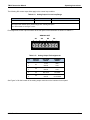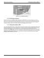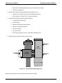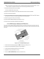
1
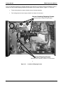
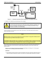
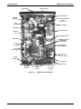
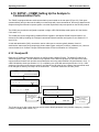
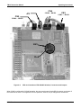
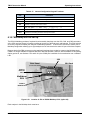
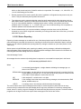
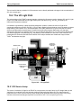
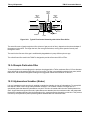
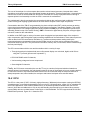
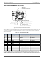
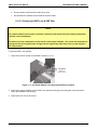
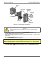
TROUBLESHOOTING & REPAIR
TML87 Instruction Manual
• Make sure the baud rate, word length, and stop bit settings between modem and analyzer match, see
Section 6.12.2.6. and Section 6.10.
• Use the RS-232 test function to send “w” characters to the modem, terminal or computer; See Section
6.10.10.
• Get your terminal, modem or computer to transmit data to the analyzer (holding down the space bar is one
way). The green LED on the rear panel should flicker as the instrument is receiving data.
• Make sure that the communications software is functioning properly.
Further help with serial communications is available in a separate manual “RS-232 Manual”, Teledyne
Instruments part number 013500000, available online at http://www.Teledyne-ML.com
11.5.11 PMT Sensor
The photo multiplier tube detects the light emitted by the UV excited fluorescence of SO2. It has a gain of about
500000 to 1000000. It is not possible to test the detector outside of the instrument in the field. The best way to
determine if the PMT is working properly is by using the optical test (OTEST), which is described in Section 6.9.5.
The basic method to diagnose a PMT fault is to eliminate the other components using ETEST, OTEST and
specific tests for other sub-assemblies.
11.5.12 PMT Preamplifier Board
To check the correct operation of the preamplifier board, we suggest the technician carry out the electrical and
optical tests described in 6.8.5 and 6.8.6. If the ETEST fails, the preamplifier board may be faulty.
11.5.13 PMT Temperature Control PCA
The TEC control printed circuit assembly is located on the sensor housing assembly, under the slanted shroud,
next to the cooling fins and directly above the cooling fan.
If the red LED located on the top edge of this assembly is not glowing the control circuit is not receiving power.
Check the analyzer’s power supply, the Relay board’s power distribution circuitry and the wiring connecting them
to the PMT temperature control PCA.
TEC Control Test Points
Four test points are also located at the top of this assembly. They are numbered left to right start with the T1
point immediately to the right of the power status LED. These test points provide information regarding the
functioning of the control circuit.
• To determine the current running through the control circuit, measure the voltage between T1 and T2.
Multiply that voltage by 10.
• To determine the drive voltage being supplied by the control circuit to the TEC, measure the voltage
between T2 and T3.
•
If this voltage is zero, the TEC circuitry is most likely open.
Or,
240
05496 Rev A6