1
TML87 Instruction Manual
Operating Instructions
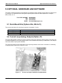
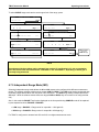
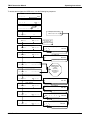
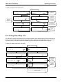
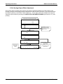
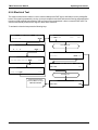
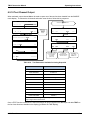
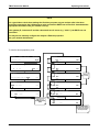
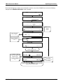
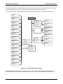
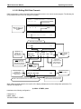
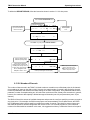
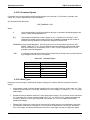
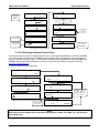
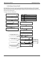
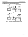
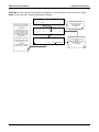
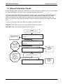
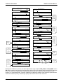
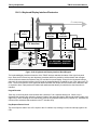
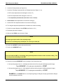
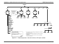
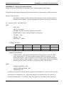
To enter the signal I/O test mode, press:
SAMPLE
RANGE = 500.0 PPB
< TST TST > CAL
SAMPLE
8
DIAG
H2S =XXX.X
SETUP
PREV NEXT JUMP
DIAG I / O
ENTER SETUP PASS : 818
1
8
SIGNAL I / O
ENTR EXIT
EXIT returns
to the main
SAMPLE display
ENTR EXIT
EXT_ZERO_CAL=OFF
PREV NEXT JUMP
PRNT EXIT
EXAMPLE
SETUP X.X
CFG DAS RNGE PASS CLK MORE
SETUP X.X
DIAG I / O
PRIMARY SETUP MENU
1
EXIT
COMM VARS DIAG
ENTR EXIT
ST_CONC_VALID = ON
PREV NEXT JUMP
EXIT
Use the JUMP key to
go directly to a
specific signal
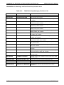
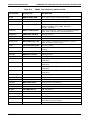
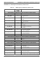
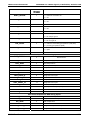
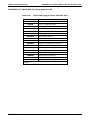
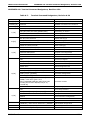
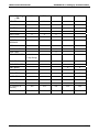
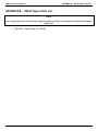
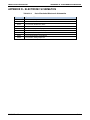
See Appendix A-4 for
a complete list of
available SIGNALS
JUMP TO: 12
2
DIAG I / O
SECONDARY SETUP MENU
Use the NEXT & PREV
keys to move between
signal types.
ON PRNT EXIT
EXAMPLE:
Enter 12 to Jump to
12) ST_CONC_VALID
Exit to return
to the
DIAG menu
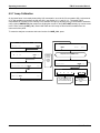
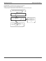
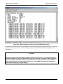
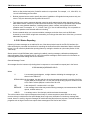
Pressing the PRNT key will send a formatted printout to the serial port and can be
captured with a computer or other output device.
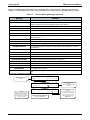
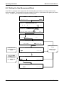
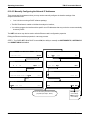
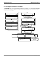
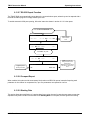
6.9.3 Analog Output Step Test
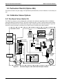
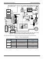
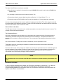
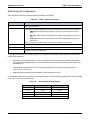
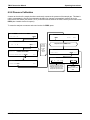
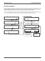
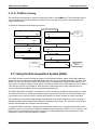
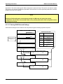
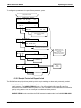
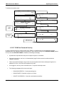
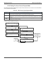
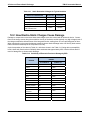
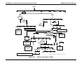
This test can be used to check the accuracy and proper operation of the analog outputs. The test forces all four
analog output channels to produce signals ranging from 0% to 100% of the full scale range in 20% increments.
This test is useful to verify the operation of the data logging/recording devices attached to the analyzer.
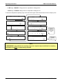
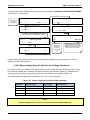
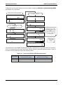
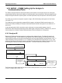
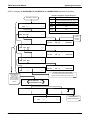
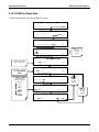
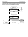
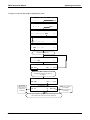
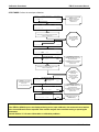
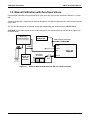
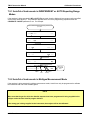
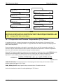
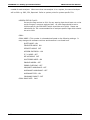
To begin the Analog Output Step Test press:
SAMPLE
RANGE = 500.0 PPB
H2S =XXX.X
DIAG
SETUP
NEXT
< TST TST > CAL
SAMPLE
8
ENTER SETUP PASS : 818
1
8
SETUP X.X
ENTR EXIT
PREV
ANALOG OUTPUT
NEXT
DIAG AOUT
PRIMARY SETUP MENU
EXIT
EXIT
ENTR
[0%]
EXIT
ANALOG OUTPUT
0%
DIAG AOUT
SECONDARY SETUP MENU
COMM VARS DIAG
ENTR EXIT
DIAG
CFG DAS RNGE PASS CLK MORE
SETUP X.X
SIGNAL I / O
EXIT
Performs
analog output
step test.
0% - 100%
Exit-Exit
returns to the
DIAG menu
ANALOG OUTPUT
EXIT
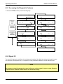
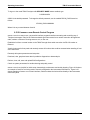
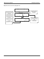
Pressing the key under “0%” while performing the test will
pause the test at that level. Brackets will appear around
the value: example: [20%] Pressing the same key again
will resume the test.
05496 Rev A6
71