1
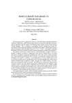
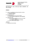
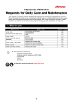
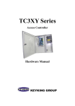
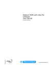
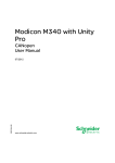
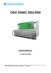
SA-CMU-SR-V1
User Manual
SA-CMU-SR-V1
Control Management Unit / SNMP AGENT
USER MANUAL
Version
Revision
Document name
1.1
15 January 2003
UM_SA-CMU-SR-V1_v1-1.doc
SA-CMU-SR-V1
User Manual
© Copyright ©2002 by AccessDSL GmbH. The contents of this publication may not be
reproduced in any part or as a whole, transcribed, stored in a retrieval system, translated into
any language, or transmitted in any form or by any means, electronic, mechanical, magnetic,
optical, chemical, photocopying, manual, or otherwise, without the prior written permission of
AccessDSL GmbH. Published AccessDSL GmbH. All rights reserved.
S-Access GmbH
Oberhausenstrasse 47
8907 Wettswil a/A
Switzerland
Page
2 of 18
Tel: +41 44 700 31 11
Fax: +41 44 700 31 03
Email: [email protected]
WEB: www.s-access.ch
SA-CMU-SR-V1
User Manual
VERSION CONTROL.......................................................................................................... 5
1
GENERAL INFORMATION........................................................................................ 6
1.1
Features ............................................................................................................ 6
2
CMU FRONT PANEL DESCRIPTION ....................................................................... 7
3
SYSTEM OVERVIEW ................................................................................................ 8
4
5
3.1
Monitor (RS-232) Interface................................................................................ 8
3.2
Jumper configuration....................................................................................... 10
3.3
CMU Power Concept ...................................................................................... 10
3.4
External Clock ................................................................................................. 11
3.5
TMN (RS-485) Interface.................................................................................. 11
3.6
Alarm Relays................................................................................................... 11
3.7
Auxiliary +5VDC Generation ............................................................................. 11
MANAGEMENT SYSTEM ....................................................................................... 12
4.1
General description ......................................................................................... 12
4.2
Description of the SNMP Protocol of the Management System...................... 12
4.3
Local Interconnection. ..................................................................................... 13
CONNECTORS ........................................................................................................ 14
5.1
Monitor Connector........................................................................................... 14
5.2
TMN Connector............................................................................................... 14
5.3
Alarm Relay Connector ................................................................................... 15
5.4
External Clock Input Connector ...................................................................... 15
5.5
Ethernet connector.......................................................................................... 15
TECHNICAL SPECIFICATION ......................................................................................... 17
5.6
Interfaces ........................................................................................................ 17
5.7
5.6.1
Ethernet Interface.............................................................................. 17
5.6.2
Monitor Interface ............................................................................... 17
5.6.3
TMN Interface.................................................................................... 17
External Clock Input ........................................................................................ 17
5.8
Power Supply .................................................................................................. 17
5.9
Environmental ................................................................................................. 17
S-Access GmbH
Oberhausenstrasse 47
8907 Wettswil a/A
Switzerland
Page
3 of 18
Tel: +41 44 700 31 11
Fax: +41 44 700 31 03
Email: [email protected]
WEB: www.s-access.ch
SA-CMU-SR-V1
User Manual
5.9.1
Climatic Conditions............................................................................ 17
5.9.2
Safety ................................................................................................ 18
5.9.3
EMC .................................................................................................. 18
5.10 Physical Dimensions ....................................................................................... 18
S-Access GmbH
Oberhausenstrasse 47
8907 Wettswil a/A
Switzerland
Page
4 of 18
Tel: +41 44 700 31 11
Fax: +41 44 700 31 03
Email: [email protected]
WEB: www.s-access.ch
SA-CMU-SR-V1
User Manual
VERSION CONTROL
Version
Date
Major changes to previous version
1.0
14.11.2002
Initial version.
1.1
15.01.2003
Change power consumption
S-Access GmbH
Oberhausenstrasse 47
8907 Wettswil a/A
Switzerland
Page
5 of 18
Tel: +41 44 700 31 11
Fax: +41 44 700 31 03
Email: [email protected]
WEB: www.s-access.ch
SA-CMU-SR-V1
User Manual
1 GENERAL INFORMATION
This manual is a general specification of the SNMP AGENT FOR HDSL MODEM named CMU
(common management unit).
1.1
Features
This CMU has the following features:
• SNMP Agent
• Management until 96 LTU in one or two sub-rack
• Ethernet interface 10Base-T 10 Mb
• Local control via RS-485
• Configuration using a RS-232 connector with the same philosophy that the LTU menu
• Supervision of the two -48VDC input powers supplies (-48V_A and -48V_B from the PSB)
• Distribution and supervision of the external clock
• Collection of the alarms of all the LTUs in a sub-rack and activation of the appropriate alarm
relay
• Interfacing the RS-232 monitor to the LTUs
• Interfacing the RS-485 bus to the LTUs, thus providing TMN facilities
• Generation of the local +5VDC auxiliary power supply
The CMU together with 12 LTUs forms a fully equipped 19” sub-rack. The CMU is connected to
the LTUs over the backplane and powered by dual -48 VDC inputs via the PSB.
S-Access GmbH
Oberhausenstrasse 47
8907 Wettswil a/A
Switzerland
Page
6 of 18
Tel: +41 44 700 31 11
Fax: +41 44 700 31 03
Email: [email protected]
WEB: www.s-access.ch
SA-CMU-SR-V1
User Manual
2 CMU FRONT PANEL DESCRIPTION
CMU
A
B
48 V
STATUS
ETHERNET
RS-485
MONITOR
ALARM
Power Leds.
Green LEDs for the power supply A & B status
Status Led
Green LED for normal operation.
Red for boot.
Blinking for hardware error
Ethernet Led
Green Data reception
Red Link Integrity Fail
Rs-485 Led
Green Data reception
Red Data transmission
Monitor Led
Green Data reception
Red Data Transmission
D-Sub 15 female, alarm relays connector
RELAIS
MONITOR
D-Sub 9 female, RS-232 interface for local monitor access
TMN
D-Sub 9 male, RS-485 interface for TMN access
ETHERNET
RJ-45 Ethernet 10Base-T connector
10Base-T
BNC 75Ω, external 2048kHz clock input
2048 kHz
Input
S-Access GmbH
Oberhausenstrasse 47
8907 Wettswil a/A
Switzerland
Page
7 of 18
Tel: +41 44 700 31 11
Fax: +41 44 700 31 03
Email: [email protected]
WEB: www.s-access.ch
SA-CMU-SR-V1
User Manual
3 SYSTEM OVERVIEW
3.1
Monitor (RS-232) Interface
The CMU has an RS-232 monitor interface connector on the front panel to enable the user /
operator to address the CMU or each individual LTU, monitor relevant events, display
information about the LTU and HDSL links and have full system configuration and fault
localization capabilities. The RS-232 monitor signals are converted to TTL levels and distributed
to all the LTUs via a "point-multipoint" bus over the backplane.
The terminal for the monitor should be VT100 compatible and be configured as follows:
• 9600 baud, asynchronous
• 8 bits, no parity, one stop bit
• XON/XOFF enabled
• No new line on carriage return (i.e. no line feed on carriage return)
At any one time, the CMU or only one of the LTUs can be "logically" connected to this monitor
interface. The appropriate CMU or LTU is addressed according to its physical location in the
sub-rack with %nn command.
Please note that if the auxiliary +5VDC power supply on the CMU fails, the monitor function will
cease to operate, but the functionality of the LTUs is still fully guaranteed.
The CMU monitor is similar to the LTU monitor. The main menu is:
CMU-ACU
Monitor Version V1.1
Copyright (C) 2001
+--------------------+
|
MAIN MENU
|
+--------------------+
1.
2.
3.
4.
5.
Performance management (PM)
Fault and maintenance management (FMM)
Configuration management (CM)
Security management (SM)
Exit
CMU_01> Select [1..5]: 2
The performance menu and security menu is not actual implement. With the fault and
maintenance menu you can see the next command:
S-Access GmbH
Oberhausenstrasse 47
8907 Wettswil a/A
Switzerland
Page
8 of 18
Tel: +41 44 700 31 11
Fax: +41 44 700 31 03
Email: [email protected]
WEB: www.s-access.ch
SA-CMU-SR-V1
User Manual
-------------------------------------------------------------FIRM
Display version and date of firmware
RESET
Equipment restart
INST
Display installed HDSL
ALARM
Display alarm status
M(AIN)
Return to main menu
-------------------------------------------------------------CMU_01_FMM>
In the configuration menu the command is:
-------------------------------------------------------------C(ONFIG)
Display configuration
DEFAULT
Load default configuration
LOAD
Load configuration from no volatile
STORE
Store the actual configuration and restart
IPLOC
IPNMS
COMM
NETW
GATW
dirIP
[1,2] dirIP
com
[1,2] red
[1,2] red gatw
POLLTIM [100..900]
LOCTIM [100..3000]
REMTIM [100..5000]
WIRES
[2,4,4x]
MAXRACK [0..1]
MAXBOARD [1..48]
Set
Set
Set
Set
Set
local IP address
IP NMS 1,2 address
comunity
network table 1,2
gateways 1,2
Polling Temporization polling (ms)
T. local answer (ms)
T. remote answer (ms)
Number of wires: 2, 4 o 4 crossed
Bigger rack address
Lower rack address
LANG
Change language('English')
M(AIN)
Return to main menu
-------------------------------------------------------------CMU_01_CM>
S-Access GmbH
Oberhausenstrasse 47
8907 Wettswil a/A
Switzerland
Page
9 of 18
Tel: +41 44 700 31 11
Fax: +41 44 700 31 03
Email: [email protected]
WEB: www.s-access.ch
SA-CMU-SR-V1
3.2
User Manual
Jumper configuration
The CMU have the next configuration jumper:
Jumper
Description
BOOT
ON
It is possible to use the boot menu
J2
OFF The RX Bus monitor is disconnect of back-panel
J3
OFF The TX Bus monitor is disconnect of back-panel
J7
OFF Disconnect the status signal of 2,048 Mbis clock from backpanel
J8
OFF Disconnect 2,048 Mbis clock from back-panel
J1
Disable the 48V B alarm
J10
ON
Termination impedance of RS-485 TX bus
J11
ON
Termination impedance of RS-485 TX bus
J4-J6-J5
3.3
ON
J4
J6
J5
RACK ADDRESS
OFF
OFF
OFF
0
OFF
OFF
ON
1
OFF
ON
OFF
2
OFF
ON
ON
3
ON
OFF
OFF
4
ON
OFF
ON
5
ON
ON
OFF
6
ON
ON
ON
7
CMU Power Concept
The CMU is supplied with (dual) -48VDC (referenced to 0 VDC of the exchange battery) by the
PSB via the sub-rack backplane. The CMU converts this -48VDC to it’s +5VDC onboard supply,
and this +5VDC is used simultaneously for the auxiliary supply for the "pull-up" voltage of the
"open-collector" alarm outputs of the LTUs. If one of the dual 48VDC turns off, the CMU activates
the non-urgent alarm.
The ground reference of the secondary voltage is tied to FPE (Functional Protective Earth). This
is done over the backplane as well as over the sub-rack with its front-panels.
S-Access GmbH
Oberhausenstrasse 47
8907 Wettswil a/A
Switzerland
Page
10 of 18
Tel: +41 44 700 31 11
Fax: +41 44 700 31 03
Email: [email protected]
WEB: www.s-access.ch
SA-CMU-SR-V1
3.4
User Manual
External Clock
The CMU supervises and distributes the external 2048 kHz clock input. It has a 75Ω BNC input,
which is transformer, coupled.
The clock input is converted to TTL level and driven to the LTUs over the backplane. This is to
enable the LTUs' E1 interfaces to be synchronized to a central master clock, if needed.
The minimum 0.75 Vpk clock input (ITU-T G.703, Sec. 10) can be further attenuated up to -6 dB
without disruption to the external clock distribution over the backplane, and before a Loss of
External Clock (LOXCK) alarm is asserted over the backplane to the LTUs.
3.5
TMN (RS-485) Interface
The CMU provides a Telecommunications Management Network (TMN) interface. The RS-485
signals are wired to the backplane and distributed to all the LTUs in the same sub-rack.
The CMU can directly address the individual LTUs with the appropriate protocol.
If there is more than one sub-rack in a shelf, the linking of the RS-485 buses between sub-racks
must be realized over a bus connection from the front panel of the various CMU s.
The RS-485 interface is operable in either half-duplex (default) or full-duplex modes. Due to the
physical bus-loading limits, up to a maximum of 31 LTUs may be connected to the RS-485 bus
at any one time.
3.6
Alarm Relays
The urgent and non-urgent alarm relays for a sub-rack are located on the CMU. The "potentialfree" alarm relays' outputs are as follows:
• Urgent Alarm Normally Open
• Urgent Alarm Normally Closed
• Non-Urgent Alarm Normally Open
• Non-Urgent Alarm Normally Closed
•
Each LTU in the sub-rack has two "open-collector" alarm outputs, namely an urgent and a nonurgent alarm output. These alarm outputs are "wired-OR" on the backplane to the CMU. Hence,
the CMU will activate the urgent alarm relay if one or more LTUs assert the urgent alarm. It will
activate the non-urgent alarm relay if one or more LTUs assert the non-urgent alarm or if one of
the supplies fails. Please refer to the LTU Operating Manual for the criteria for each alarm
condition.
3.7
Auxiliary +5VDC Generation
The CMU also generates a local +5VDC auxiliary supply for its onboard active components and
alarm relays. Additionally, it is used for the "pull-up" voltage for the "open-collector" alarm
outputs of the LTUs.
This auxiliary supply generation section is transformer coupled to the backplane and the
onboard active components.
This auxiliary supply will cease if both the -48 VDC supplies fail or if the onboard DC-DC
converter fails.
S-Access GmbH
Oberhausenstrasse 47
8907 Wettswil a/A
Switzerland
Page
11 of 18
Tel: +41 44 700 31 11
Fax: +41 44 700 31 03
Email: [email protected]
WEB: www.s-access.ch
SA-CMU-SR-V1
User Manual
4 MANAGEMENT SYSTEM
4.1
General description
The Management System arises in the face of the necessity of remote control of HDSL modem
as well as of obtaining statistical of operation of these.
The main functions of the Management System are:
•
•
•
•
•
4.2
Remote Configuration of the modem.
Control of their state and parameters.
Reception of alarms of the modem.
Management of the remote modem.
Get statistical, Etc.
Description of the SNMP Protocol of the Management System
The Management System is based on the protocol of communications SNMP. This protocol will
use primitive of the type petition and answer among the Management Center and the elements
to control. It is implemented on the layer TCP/UDP that is mounted on the Protocol Internet (IP).
The protocol SNMP offers a system of security and protection for accesses to management
variable defining for it the community concept. For each community and variable is defined the
access right to this variable from SNMP's Center. In case this access rights are violated,
messages are sent (traps) of error to the Center of Administration configured in the Element
Agent.
SNMP
TCP
RS-485
UDP
IP
ETHERNET
RED LOCAL
Figure 2.SNMP Protocol architecture.
S-Access GmbH
Oberhausenstrasse 47
8907 Wettswil a/A
Switzerland
Page
12 of 18
Tel: +41 44 700 31 11
Fax: +41 44 700 31 03
Email: [email protected]
WEB: www.s-access.ch
SA-CMU-SR-V1
4.3
User Manual
Local Interconnection.
We denominate Local Interconnection (VIL) to the bus that interconnect to each other to all the
modem local that belong to the Management Unit of with the SNMP Agent.
The function of this bus is the one of allowing the Agent the supervision of the modem of him
clerks.
The VIL bus is implemented using a shared bus (an element Master and multiple Slaves) using
for it the electric norm RS485.
Master's function in the bus RS485 (VIL) is made by the SNMP Agent.
The Slaves elements of the VIL are the HDSL modem.
Following this topologic of shared bus (Master - Slaves) the function of sending messages for
the VIL are made by the SNMP Agent .The modem only transmit the answer messages for
expressed petition of the SNMP Agent. This way, the Agent goes sending messages to all the
modem, so much local as remote, continually and in a recurrent way.
Each element located in the VIL will have a identifying (ID) that will be its node address in the
bus. The SNMP Agent will use this to address to the different modem connected to the VIL bus.
The modem will only respond to messages that correspond to its own ID or to the ID of its
modem remote associate
S-Access GmbH
Oberhausenstrasse 47
8907 Wettswil a/A
Switzerland
Page
13 of 18
Tel: +41 44 700 31 11
Fax: +41 44 700 31 03
Email: [email protected]
WEB: www.s-access.ch
SA-CMU-SR-V1
User Manual
5 CONNECTORS
5.1
Monitor Connector
Type: Sub-D9, female
5
Pin
Signal
Description
1
FPE
Functional Protective Earth
2
TxD
RS-232 Serial Data Output Signal
3
RxD
RS-232 Serial Data Input Signal
5
GND
RS-232 Signal Ground
9
6
1
Note: All other pins are not connected on the CMU.
5.2
TMN Connector
Type: Sub-D9, male
1
6
9
5
Pin
Signal
Description
1
5
6
7
8
9
FPE
GND
TX_485+
TX_485RX_485+
RX_485-
Functional Protective Earth
RS-485 Signal Ground
RS_485 Serial Data Output (pos)
RS_485 Serial Data Output (neg)
RS_485 Serial Data Input (pos)
RS_485 Serial Data Input (neg)
Note: All other pins are not connected on the CMU.
S-Access GmbH
Oberhausenstrasse 47
8907 Wettswil a/A
Switzerland
Page
14 of 18
Tel: +41 44 700 31 11
Fax: +41 44 700 31 03
Email: [email protected]
WEB: www.s-access.ch
SA-CMU-SR-V1
5.3
User Manual
Alarm Relay Connector
Type: Sub-D15, female
8
15
9
1
Pin
Signal
Description
1
FPE
Functional Protective Earth
6
A_NU_NO
Non-Urgent Alarm, normally open
7
A_U_NO
Urgent Alarm, normally open
8
FPE
Functional Protective Earth
13
A_NU_NC
Non-Urgent Alarm, normally closed
14
A_U_NC
Urgent Alarm, normally closed
15
A_COM
Common Alarm Contact
Note: All other pins are not connected on the CMU.
5.4
External Clock Input Connector
Type: BNC 75Ω
Note: The input is transformer coupled.
5.5
Ethernet connector
Pin
1
2
3
6
Signal
TD
TDN
RD
RDN
S-Access GmbH
Oberhausenstrasse 47
8907 Wettswil a/A
Switzerland
Page
15 of 18
Description
Transmission
Transmission
Reception
Reception
Tel: +41 44 700 31 11
Fax: +41 44 700 31 03
Email: [email protected]
WEB: www.s-access.ch
SA-CMU-SR-V1
User Manual
S-Access GmbH
Oberhausenstrasse 47
8907 Wettswil a/A
Switzerland
Page
16 of 18
Tel: +41 44 700 31 11
Fax: +41 44 700 31 03
Email: [email protected]
WEB: www.s-access.ch
SA-CMU-SR-V1
User Manual
TECHNICAL SPECIFICATION
5.6
Interfaces
5.6.1 Ethernet Interface
Signal Level:
Data Rate:
Protocol:
Connector Type:
IEEE Std 802.3
10 Mbit/s
IEEE Std 802.3,IP/UDP, SNMP, TFTP
RJ-45
5.6.2 Monitor Interface
Signal Level:
Data Rate:
Protocol:
Connector Type:
RS-232
9600 Baud, Asynchronous
8 Bit, No Parity, 1 Stop Bit
No Linefeed with Carriage Return
XON/XOFF enabled
Sub-D9 female
5.6.3 TMN Interface
Signal Level:
Data Rate:
Protocol:
Connector Type:
5.7
RS-485
9600 Baud, Asynchronous
Proprietary
Sub-D9 male
External Clock Input
Norm referred:
ITU-T Rec. G.703, Sec. 10
Maximum peak voltage: 1.5 Vpk @ 75 Ω
Minimum peak voltage:
5.8
Power Supply
Local Powering:
Power Consumption:
5.9
0.75 Vpk @ 75 Ω (with up to 6 dB attenuation)
-40VDC .. 72VDC (redundant via PSB)
max. 1.5W (all alarms off), max 1.7W (all alarms on)
Environmental
5.9.1 Climatic Conditions
Storage:
ETS 300 019-1-1 Class 1.2
S-Access GmbH
Oberhausenstrasse 47
8907 Wettswil a/A
Switzerland
Page
17 of 18
(-25°C … +55°C)
Tel: +41 44 700 31 11
Fax: +41 44 700 31 03
Email: [email protected]
WEB: www.s-access.ch
SA-CMU-SR-V1
Transportation:
Operation:
User Manual
ETS 300 019-1-2 Class 2.3
ETS 300 019-1-3 Class 3.2
(-40°C … +70°C)
(-5°C … +45°C)
5.9.2 Safety
According to EN 60950
5.9.3 EMC
According to EN 55022 , Class B
5.10 Physical Dimensions
19“ Plug-in unit: height: 259 mm (6 HE), width: 30 mm
PCB dimensions: height: 234 mm, length: 220 mm
S-Access GmbH
Oberhausenstrasse 47
8907 Wettswil a/A
Switzerland
Page
18 of 18
Tel: +41 44 700 31 11
Fax: +41 44 700 31 03
Email: [email protected]
WEB: www.s-access.ch