1
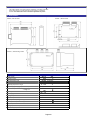
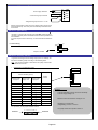
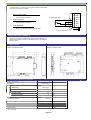
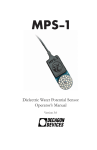
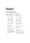
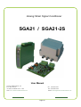
Analog Strain Signal Conditioner
SGA21 / SGA21-2S
User Manual
Tension Measurement, Inc.
P.O. Box 740755,
Arvada, CO 80006-0755 USA
Web: www.tension-measurement.com
Ph: (303)465-1011
Fax: (303)466-9761
Email: [email protected]
Page 1/8
1. Introduction
The SGA21 device is an analog sensor conditioner. It is mainly used with
strain gage sensors such as load cells, torque sensors or pressure
sensors. The SGA21-2S version includes 2 adjustable set points.
2. Presentation
SGA21-1, Board model
SGA21, DIN rail model
SGA21-3, IP65 Housing model
3. General specifications
24+/-4
0.05
VDC
Overall accuracy
Zero temperature drift
<0.035
%/°C (FS*)
Span temperature drift
<0.02
%/°C (FS*)
0…+70
°C
Power supply
Operating temperature range
Sensor supply voltage (jumper selection)
Min. sensor impedance
- voltage 3, 5V
- voltage 10V
Span adjustment
Max. supply current SGA21/SGA21-2S
3, 5, 10
80
160
0.15 … 12
120/170
%
V
Ω
mV/V
mA
+/-10, 0-10
4-20
mA
Load impedance (Voltage output)
>2000
Ω
Load impedance (Current output)
<500
<1
10
20
Voltage output
Current output
Output capacitive load
Filter (jumper selection)
Bandwidth (up to)
V
Ω
nF
Hz
KHz
*FS = Full Scale
Page 2/8
4. Wiring and setting devices positioning
4/6 wire sensor selection
4.1 & 5
Sensor supply voltage selection
4.2 & 5
‘Cal’ push button
4.8
2
3
4
5
6
7
3V
5V
10V
1
8
9 10 11 12
Power supply led
Sensor connection
4.1 & 5
P2
Zero adjustment
4.6
P3
Power supply and output
signal connection
4.3
Sensor sensitivity selection
4.5
P1
Span adjustment
4.7
Filtering selection
4.4
4.1 Sensor connections
The SGA21 is able to manage up to 4 load cells (350Ω) connected in
parallel through a junction box (Excitaiton jumper must be set to 5VDC or 3VDC for 4 load cell systems).
• Sensor connection
4 wire sensor. The two jumpers stay in place.
6 wire sensor. The two jumpers are removed.
Gnd
7
Gnd
6
Sens -
Ref-
6
Sens -
5
Sens +
Ref+
5
Sens +
Ex+
4
Ex +
Sig-
3
Sig Sig +
Ex -
7
4 wire sensor
Ex+
4
Ex +
Sig-
3
Sig -
6 wire sensor
Sig+
2
Sig +
Sig+
2
Ex-
1
Ex -
Ex-
1
2 jumpers removed
2 jumpers set in place
4.2 Sensor supply voltage
Set the jumper in position corresponding to the selected voltage :
3VDC, 5VDC or 10VDC.
The load cells are generally supplied in 5V (default value).
3V voltage is useful for some particular sensors, 10V is recommended
for low sensitivity (or low output signal) sensors.
Warning :
With 10VDC supply voltage, only 2 load cells (350 Ω) can be
connected.
For load cells used in ATEX area and protected by Zener
barriers, do not use 10V supply voltage.
Page 3/8
4.3 Power supply and analog outputs
Power supply 24VDC±4
Current analog output 4/20mA
12
+ 24V
11
Gnd
10
Gnd
9
Iout
8
Vout
Voltage analog output 0/10V or +/-10V
4/20mA current analog output and 0/10V voltage analog output can be
used simultaneously. The ‘Gnd’ points are internally connected in the
circuit board.
4.4 Sensor signal filtering
The filter is a second order low-pass type with 10Hz cutting frequency.
The filter is generally used to eliminate troubles caused by vibrations of
the installation.
If a faster response time is necessary, it’s recommended to disable the
filter.
• Enable filtering
:
without filter
filter
Jumper to set filter
4.5 Sensor sensitivity selection
To get the correct signal on the analog output (0/10V or 4/20mA), set
the sensor sensitivity jumper according to the following table:
Note : The load cell sensitivity is indicated on the quality control sheet
attached with the load cell.
•
Positionning of configuration jumper
1
2
3
4
5
6
7
8
9
Sensor sensitivity (mV/V)
Jumper
position
Sensor power
supply 3V
Sensor power
supply 10V
Sensor power
supply 5V
0.50 Æ 0.66
0.15 Æ 0.20
0.30 Æ 0.40
X
0.66 Æ 0.93
0.20 Æ 0.28
0.40 Æ 0.56
1
0.93 Æ 1.30
0.28 Æ 0.39
0.56 Æ 0.78
2
1.30 Æ 1.80
0.39 Æ 0.54
0.78 Æ 1.08
3
1.80 Æ 2.50
0.54 Æ 0.75
1.08 Æ 1.50
4
2.50 Æ 3.40
0.75 Æ 1.02
1.50 Æ 2.05
5
3.40 Æ 4.65
1.02 Æ 1.40
2.05 Æ 2.80
6
4.65 Æ 6.50
1.40 Æ 1.95
2.80 Æ 3.90
7
6.50 Æ 8.80
1.95 Æ 2.65
3.90 Æ 5.30
8
8.80 Æ 12.50
2.65 Æ 3.75
5.30 Æ 7.50
9
Example
Load cell with 500kg capacity and 2mV/V sensitivity.
Load cell supply voltage : 5V
Maximum load to be measured : 200kg for 10V
Sensitivity for a 200kg load =
(200kg/500kg) x 2mV/V = 0.8mV/V
For X position, put the jumper between 8 and 9.
Position 1
1 2 3 4 5 6 7 8 9
The jumper will be set in position number 3
Position X
Page 4/8
4.6 Zero adjustment
•
Verify that no load (except the load receptor) is applied on the
load cell.
•
Approach the zero with P2 potentiometer and make a fine
adjustment with P3 potentiometer.
- Analog output 0/10V : voltmeter
displays 0V.
- Analog output 4/20mA : ampere meter
displays 4mA.
4.7 Span adjustment
•
After zero adjustment, apply a known load on the load cell.
•
Adjust span with P1 potentiometer until the analog output signal
complies with the applied load.
Example : If the applied load is the maximum load,
adjust P1 until output signal is 10V or 20mA.
If the applied load is not the max. load. For example,
with a 200kg load cell and only a 100kg load available
for the adjustment : Adjust P1 to obtain :
10V x (100kg / 200kg) = 5V (or 12mA)
•
Remove the load and verify the zero adjustment. If necessary,
make a new zero adjustment followed by a new span
adjustment.
4.8 Shunt calibration / control
If the load cell specifications are known :
- Output resistance (Z) and Sensitivity (S).
It is not necessary to put a calibrated weight on the load cell for span
adjustment.
You just have to :
1. Connect the load cell
2. Select the load cell sensitivity (4.5)
3. Adjust the zero (4.6)
Then :
4. While maintaining pressure on the push button ‘Cal’, adjust the
output voltage (or current) with P1 potentiometer. The
adjustment value is defined by the following formula :
- For 0/10V analog output : V(V) = [(Z+1) / S] x 0.025
- For 4/20mA analog output : I(mA) = [(Z+1) / S] x 0.04 + 4
With Z = output load cell resistance (Ω)
S = Load cell sensitivity (mV/V)
5. Release the push button ‘Cal’ and check the zero adjustment.
If necessary, make a new zero adjustment and start again this
process.
Example
Load cell with 500kg capacity, 2mV/V sensitivity and 350Ω output resistance
Voltage of 0/10V output (to obtain 10V at 500kg)
V = [(350Ω + 1) / 2mV/V] x 0.025 = 4.387V
Output current (to obtain 20mA at 500kg)
I = [(350Ω + 1) / 2mV/V] x 0.04 + 4 = 11.02mA
In case of calculation result > 10V or 20mA please call our offices
Page 5/8
5. Optional potentiometer input
To obtain a 0/10V (or 4/20mA) output signal for the total potentiometer
coarse, set up the SGA21 as follow :
•
Sensor supply voltage
-
•
Potentiometer sensor
Put the jumper in position 3V
Sensor sensitivity
-
•
Put the jumper in position 9
Span adjustment
-
Make a fine adjustment with P1 potentiometer.
2 jumpers set in place
6. Set points option : SGA21-2S
The SGA21-2S version includes all the previous functionalities and, in
addition, the possibility to manage 2 set points thanks to an additional
electronic board.
6.1 Presentation
SGA21-2S, DIN rail model
SGA21-1, Board model
6.2 General specifications of set points
2
Number of set points
Adjustment
Relay features
Technology
Potentiometers
Photorelays
On-state current max (@40°C)
0.4
Off-state voltage
55
V
2
Ω
On-state resistance
Isolation voltage
Functionning direction
Hysteresis
Holding time
Latch
Response time
A
2500
Vrms
Selected
1.1 / 0.2
% FS*
5 / 600
ms
Yes
7
* FS = Full scale
Page 6/8
ms
7
Gnd
6
Sens -
5
Sens +
4
Ex +
3
Sig -
2
Sig +
1
Ex -
6.3 Wiring and setting devices positionning
Measurement points for set points
6.8
1V1
SP2
GND
0V reference for measurement points
SP1
SP2
Logic Positive/Negative
Hysteresis Min / Max
Holding time Min / Max
Latch Yes/no
SP1
Set point status LEDs
Logic Positive/Negative
Hysteresis Min / Max
Holding time Min / Max
Latch Yes/no
V2
SP1
SP2
Set point adjustment potentiometers
6.8
13 14
15 16 17 18
‘Reset Latch’ connector
6.10
Set points outputs 1 & 2
6.4
Note : Each set point can be adjusted separately.
6.4 Photorelays connections
or
18
or
Photorelay 2
17
16
or
15
or
Photorelay 1
6.5 Photorelays functioning direction
The photorelays can be used with positive or negative logic. For this,
put or remove the corresponding jumper (Logic Positive/Negative).
6.6 Set points functioning
negative signal
Positive signal
Voltage
Voltage
0
Set point
Hysteresis
Time
Hysteresis
Set point
0
Time
Relay output
Relay output
1
1
t
Positive logic Jumper ON
t
Negative logic Jumper OFF
0
t
1
1
0
0
Page 7/8
0
t
6.7 Hysteresis
To avoid oscillation of the set point relays, a hysteresis is applied
(jumper Hysteresis Min/Max).
-
If the jumper is removed, the hysteresis value is 20mV (0.2%
of FS).
If the jumper is in place (by default), the hysteresis value is
110mV (1.1% of FS).
6.8 Set points adjustment
The set points can be ajusted with experiments or by using a voltmeter.
Experimental adjustment : Apply on the load cell the load
corresponding to the wanted set point. Adjust the potentiometer until
the state of the corresponding light changes.
Adjustment with voltmeter : Connect the voltmeter between the
measurement points (V1 or V2) and GND (voltmeter input "-"
connected to GND ). Adjust the corresponding potentiometer to the
desired set point voltage. The adjustment error is <2% with maximum
hysteresis and <0.5% with minimum hysteresis.
Example : the SGA21 is adjusted for 10V (or 20mA)
output with max. load.
For a requested set point at 80% of max. load,
adjust the potentiometer (SP1 or SP2) to obtain
8V on measuring point.
6.9 Holding time
It is possible to maintain the set point during a minimum time
depending on the ‘Holding timeMin/Max’’ jumper position :
-
Jumper in place: Holding time = 5ms
Jumper removed: Holding time = 600ms
Voltage
Set point
Hysteresis
0
Time
t < Holding time
Relay output
1
t
0
Holding time
6.10 Latching
It is possible to latch the set point by engaging the latch function .
To enable the latch function, just remove the ‘Latch Yes/No’ jumper.
Release of latched set point is possible by powering off the SGA21 or by
realizing a short-circuit on he ‘Reset latch’ connector.
13
14
‘Reset latch’ connector
TENSION MEASUREMENT, INC.
P.O. BOX 740755
ARVADA, CO, 80006-0755 USA
Web: [email protected]
Ph: (303)465-1011
Fax: (303)466-9761
Page 8/8
Email: [email protected]