1
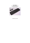
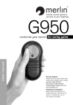
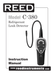
Model VC01
Temperature Calibrator
Instruction
Manual
www
reedinstruments
com
Table of Contents
Safety............................................................................................. 3
Specifications..............................................................................4-5
Instrument Description................................................................6-7
Operating Instructions...............................................................8-15
ON/OFF....................................................................................... 8
Automatic Power Off.................................................................... 8
Outputs..................................................................................8-12
Calibration............................................................................13-15
Battery Replacement.................................................................... 16
For service (repairs or calibration) on this or any other REED product
or information on other REED products, contact REED Instruments at
[email protected]
www
reedinstruments
com
2
Safety Information
To ensure the safety operation, the following signs are used only as
specified in this instruction manual.
WARNING Indicates that the current operation does not comply with
correct instruction. Therefore causing potential hazards to the user or
instrument. Also indicates how to avoid such hazards.
! CAUTION Indicates that if the current operation does not comply with
correct instruction. Therefore causing potential hazards to the instrument.
Also indicates how to avoid incorrect operation.
NOTE Serves as a sign to remind the user that they must understand
the correct operation of the simulator and its characteristics.
To prevent the user and the instrument from electric shock and other
hazards, it is necessary to follow the following regulations:
WARNING
Warning -
• Do not operate the instrument where flammable gas or explosive
gas or vapor are exposed. This is extremely dangerous
• Never apply more than 30V between any two terminals, or between any
terminal and ground
Caution -
! CAUTION
• The split case (top and bottom) is not to be removed, unless by
qualified technicians
• To clean the instrument, periodically wipe the case with a damp cloth
and mild detergent, do not use any corrosive solvents
Note -
NOTE
• For optimal accuracy, allow the instrument to warm up 5 minutes
before operating
• If the automatic reference-junction temperature compensation of the
instrument deviates from its designed accuracy, contact a
qualified REED technician
www
reedinstruments
com
3
Specifications - Output Functions
Applicable range from 18 to 28°C, within one year after calibration
Output Range
100mV
DCV
10000 mV
OHM
TC
400Ω
-10.00mV to
110.00mV
-100.00mV to
1100.00mV
0.0 to 400.0Ω
0.01mV
0.1mV
0.1Ω
R
-40 to 1760°C
1°C
S
-20 to 1760°C
1°C
B
RTD
Output Range Resolution
400 to 1800°C
1°C
E
-200.0 to 000.0°C
0.1°C
K
-200.0 to 370.0°C
0.1°C
J
-200.0 to 200.0°C
0.1°C
T
-200.0 to 400.0°C
0.1°C
N
-200.0 to 1300.0°C
0.1°C
Pt100
-200 to 850.0°C
0.1°C
Cµ50
-50.0 to 150°C
0.1°C
Accuracy
Note
0.05% of set
value 30µV
0.05% of set
value 0.3mV
Max. output
current
±2mA
±0.05% of set
value ±0.2Ω
1mA excit.
current
±0.05% of set
value ±3°C
(≤100°C)
±0.05% of set
value ±2°C
(>100°C)
±0.05% of set
value ±3°C
By using
(400°C to
ITS-90
600°C) ±0.05% temperature
of set value
scale
±2°C (>600°C)
±0.05% of set
value ±2°C
(≤-100°C)
±0.05% of set
value ±1°C
(>-100°C)
±0.05% of set
value ±0.6°C
By using
Pt100-385
Notes 1 & 2
Note 1: Without accessory lead resistance
Note 2: Range of exciting current: 0.5mA to 2mA; max. output voltage: ≤2V
• The accuracies indicated do not include the error of internal temperature
compensation caused by a sensor. The range of the internal temperature
compensation sensor is from -10 to 50°C with its compensating error up to 0.5°C
• Temperature coefficient: ±0.005% of range per °C for the temperature ranges from
0 to 18°C and from 28 to 50°C
www
reedinstruments
com
4
General Specifications
Operating temperature:
Operating relative humidity:
Storage temperature:
Storage humidity:
Max. permitted voltage:
Power supply:
Battery life:
Dimensions:
Weight:
Includes:
Safety:
0°C to 50°C
≤80% RH
≤-10°C to 55°C
≤90% RH
30V (between any two terminals or
between any terminal and ground)
Single 9V battery (ANSI/NEDA 1604A
or IEC6LR619V alkaline)
Approximately 12 hours
200 × 100 × 40mm (with holster)
550g (with holster)
Set of CF-36 industrial test lead
(with alligator clips) and Instruction manual
Certified compliant to IEC1010 provisions
(Safety Standard issued by International
Electro-technical Commission)
For service on this or any other REED product or information on other
REED products, contact REED Instruments at [email protected]
www
reedinstruments
com
5
Instrument Description
1 - LCD display area
2 - Power ON/OFF button
3 - °C/°F Interchange button
4 - RJ-ON button (TC ref-junc comp)
5 - Output Zero Reset button
6 - Function Selection button
7 - Range Selection key
8Output Digit Selection button
9Output Value Setting button
10 - Output terminal
1
6
2
7
3
4
8
5
9
10
www
reedinstruments
com
6
Display Description
Indicates that the instrument is in an output state
Indicates that the instrument is in a calibration state
Indicates that the instrument is in a calibration state, denoting
that the zero point or the full scale point is now in calibration
Indicates that the instrument is performing its referencejunction compensation (Refer to subsection 5.2)
Indicates that the battery power is low and needs to be
replaced (Refer to subsection 3.1)
Indicates that the output digits need to be set
Indicates the current output value (unit of measure)
Indicates that the output signal is on
Indicates the type of thermocouple
Indicates the respective type of a RTD
www
reedinstruments
com
7
Operating Instructions
Power ON/OFF
Power-key operation
Press the Power ON/OFF button (#2 on page 6) to turn the instrument on.
Press this button again, holding for one second to turn the instrument off.
When the instrument is on, it will begin an internal self-diagnosis at which
time the full screen will be displayed (#1 on page 6). Once complete, the
instrument is ready to be used.
Automatic power-off
As a default the instrument will be set to automatically turn itself off after
10 minutes with button operation. To turn off this feature:
1) Turn the instrument off
2) Press the Power ON/OFF button (to display the full screen)
3) Press the RANG button (#7 on page 6) when the instrument is in
the maintenance state. AP-XX will display
4) Press the
button (#9 on page 6) when AP-ON is displayed.
AP-OF will now be displayed, indicating that the automatic
power-off is not on
5) Press the Power ON/OFF button to exit the maintenance state and
turn the instrument off
Outputs
The output terminal of the instrument can produce DC voltages set by the
user or simulating resistance.
! CAUTION Do not apply any voltage to the output terminal during the
operation. If any improper voltage is applied to the output terminal, it will
cause damage to the internal circuit.
continued ...
www
reedinstruments
com
8
Output Operation Procedure
Function Operation
DCV 1 V
Range
Operation
1V
Display
Set Range
0.0000 V
-0.1000 to 1.1000 V
100mV
000.00 mV
-10.00 to 110.00 mV
000.0Ω
000.0 to 400.0Ω
R
0000°C
-40 to 1760°C
S
0000°C
-20 to 1760°C
K
0000.0°C
-200 to 1370°C
E
0000.0°C
-200 to 1000°C
J
0000.0°C
-200 to 1200°C
T
0000.0°C
-200 to 400°C
B
400 °C
400 to 1800°C
OMH 400 Ω
TC
R
RTD Pt100
N
0000.0°C
-200 to 1300°C
Pt100
000.0 °C
-200 to 850°C
Cµ50
000.0 °C
-50 to 150°C
www
reedinstruments
com
9
DC Voltage Output
1)Insert one end of the test lead into the
output (TC/mV) jack of the instrument
and connect the other end to the input
of the instrument, as shown in the
diagram to the right
2)Press the FUN (Function) button to select
+
M
the V function when the unit ‘V’ appears in the display
3)Press the RANG (Range) Button to select the range of 1.0000V or
100.00mV when the display indicates the unit ‘V’ or ‘mV’
button to select the set digits for output
4)Press the
5)Press the
button to change the numerical value of the set digits.
Hold the button for one second and the value will keep varying
6)Press the ZERO button and the output will be set to
00.00mV or 0.0000V
Simulating output from thermocouple (TC)
1)Insert one end of the test lead into the output (TC/mV) jack of the
instrument and connect the other end to the input of the instrument.
As shown in the above diagram
2)Press the Fun (Function) button to select the function of a
thermocouple and the display will indicate the unit °C or the type of R
3)Press the RANG (Range) button to select an appropriate type
4)Press the
button to select the set digits for output
5)Press the
button to change the numerical value of the set digits.
Hold the button for one second and the value will keep varying
6) Automatic compensation for reference-junction temperature
continued ...
www
reedinstruments
com
10
During the direct calibration of an instrument with reference-junction
temperature compensation, it is common to press the RJ-ON button so
that the instrument can start the function of automatic reference-junction
compensation. Thus providing the required thermo-electromotive force for
output followed by displaying the symbol RJ-ON where:
output emf = emf corresponding to the set temperature
– emf corresponding to the room temperature
• It takes two seconds for the instrument to start its internal referencejunction temperature. After this, each automatic compensation takes
place at 10 second intervals
• If there is a change in the operating ambient temperature, do not start
the operation until the built-in compensating sensor has become stable
(ca. 10 minutes)
• If there is no need for the Simulator to perform the function of automatic reference-junction compensation, press the RJ-ON button and
the symbol RJ-ON will no longer appear in the display
7)Press the ZERO button and the output will be directly set to 0000°C (R
or S type), 400°C (B type) or 0000.0°C (other type)
8)Press the °C/°F button to select the unit ‘°C’or ‘°F’
Simulating output from resistance or RTD
NOTE
Resistance-simulation: The instrument produces the simulation resistance
up to 400Ω at its output terminal (RTD /Ω). The method of simulating
resistance output is to send out an appropriate voltage ‘VX’ according to
the exciting current ‘IX’ produced by the calibrated instrument. Because R
(set resistance ) = VX (output voltage) /IX( exciting current), the calibrated
device must provide an exciting current to the simulator. The exciting
current should range from 0.5mA to 2mA.
continued ...
www
reedinstruments
com
11
NOTE
Resistance-simulation: A 4-wire system is designed for the resistance
output during the calibration. If you adopt a two-wire system, you
should take into consideration the error (ca.0.1Ω) arising from the lead
resistance of the test leads. If the capacitance between the resistance
output terminal of the simulator and the tested instrument is more than
0.1µf, the simulator will produce improper resistance.
1)Insert one end of the test lead into the
output (RTD/Ω) jack of the instrument and
connect the other end to the input of the
instrument as shown in the diagram to the
right. The dedicated test leads supplied
with the simulator can be made into a
3-wire or 4-wire system for testing output
V
3W
4W
according to user’s requirement
lx
2)The display of the symbol ‘OUTPUT’
denotes the instrument is in an output state
3)Press the FUN (Function) button to select the function of resistance or
RTD when the unit ‘Ω’ or ‘°C’ and the type of the RTD ‘Pt100’ appears
in the display
4)During the use of the RTD function, press the RANG (Range) button to
select a corresponding type
button to select the set digits for output
5)Press the
6)Press the
button to change the numerical value of the set digits.
Hold the button for one second and the value will keep varying
7)Press the Zero button and the output will be directly set to 000.0°C
8)Press the °C/°F button to select the unit °C or °F
www
reedinstruments
com
12
Calibration
NOTE
To ensure accuracy of the instrument, it is recommended to calibrate your
instrument once a year. It is recommended that the following standards be
used to perform the calibration.
! CAUTION
During the operation, avoid any short circuit and never apply more than
the maximum permitted voltage to the output of the simulator and the
co-working standard device, incorrect operation may cause damage to
the internal circuits.
Selecting Standard Equipment
Calibration
Item
Stand. Output Range
Equip.
DCV 100mV
digital
meter
1V
OHM 400Ω
digital
meter
Accuracy
Recommend
max.110mV
±(10ppm+1µV)
1281 (FLUKE)
5520 (FLUKE)
or equivalent
max.1.1V
±(10ppm+5µV)
±(10ppm+5µV)
max. 2V
stand. equip. ±(80ppm+0.03µA)
±1mA excit.
Ambient Condition for Calibration
Ambient temp.:
23°C±1°C
Relative humidity: 45 to 75% RH
Warming up:
The standard equipment must be warmed up to the
given time. Do not connect the instrument to the power supply until it has
been exposed to the calibrating ambient condition for 24 hours. Then set
the instrument to a state of non-automatic shutdown followed by warming
it up for 30 minutes.
NOTE Power supply for calibration: During the calibration, the battery
needs replacing.
www
reedinstruments
com
13
Operating Output Calibration
Operate output calibration in the order of items and calibration points:
Item #
Output Range
1
DCV/1V
2
DCV/100mV
3
OHM/400Ω
Calibration Point
0
FS
0 FS
0
FS
0
FS
0
-FS
digital meter (1281)
1V Range Calibration
1)The calibration wiring is shown
in the diagram to the right
2)Press the FUN & RANG buttons
first, and then press the POWER
to enter the simulator in a state of
1V output calibration when the
symbols ‘OUTPUT’, ‘CAL 0’, ‘ON’ and the unit ‘V’ appear in the display
3)Set the digital meter to an appropriate range
4)With the output stabilized, operate the
and
buttons to set
the indication of the simulator with the reading of the digital meter
5)Press the ZERO button and the display will flash, denoting that the
calibrated point has been stored
6)Press the RANG button to display the symbol ‘CAL FS’. With the output
stabilized, repeat steps 4 & 5
7)Press the RANG button to display the symbol ‘CAL 0 FS’. With the
output stabilized, repeat steps 4 & 5
NOTE
Calibration Storage: Press the ZERO button to store the calibrated point when
the display does not flash, denoting that the calibration storage is invalid.
www
reedinstruments
com
14
100mV Range Calibration
1)The calibration wiring is shown in the diagram shown on Page 14
2)Press the FUN button to enter the simulator in a state of 100mV output
calibration when the display indicates the symbols ‘OUTPUT’, ‘CAL 0’,
‘ON’ and the unit ‘mV’
3)Repeat the operation of steps 3 to 6 in 1V Range Calibration on Page 14
Resistance Calibration digital meter (1281)
1)The calibration wiring
is shown in the
diagram to the right
2)Press the FUN button
to enter the simulator
in a state of resistance
output calibration when the display indicates the symbols ‘OUTPUT’,
‘CAL 0’, ‘ON’ and the unit ‘Ω’
3)Set the digital meter and standard source to an appropriate range,
and then set the standard source to +1mA output
4)With the output stabilized, repeat steps 4 & 5 in 1V Range Calibration
on Page 14
5)Press the RANG button to display the symbol ‘CAL FS’. With the output
stabilized, repeat steps 4 & 5 in 1V Range Calibration on Page 14
6)Change the output of the standard source to -1mA output
7)Press the RANG button to display the symbols ‘CAL 0’& ‘-’.With the
output stabilized, repeat steps 4 & 5 in 1V Range Calibration on Page 14
8)Press the RANG button to display the symbols ‘CAL FS’& ‘-’.With the
output stabilized, repeat steps 4 & 5 in 1V Range Calibration on Page 14
NOTE
Exciting current: The flow direction of the exciting current must be in line
with the calibration point, otherwise the display fails to flash, denoting that
the calibration storage is invalid.
www
reedinstruments
com
15
Replacing the Battery
WARNING
Remove the test leads and turn the instrument off before
replacing the battery.
symbol appears in the display, indicating
When the low battery
the battery power is low and the battery needs to be replace.
Follow these steps:
1)Remove the test leads and turn the instrument off
2)Remove the holster from the instrument. Open the battery cover at the
back of the instrument by unlocking it in the direction indicated
3)Replace the old battery with a new one. Put the battery cover back and
lock it in the direction indicated
Notes _ _________________________________________
________________________________________________
________________________________________________
________________________________________________
________________________________________________
________________________________________________
________________________________________________
________________________________________________
________________________________________________
For service on this or any other REED product or information on other
REED products, contact REED Instruments at [email protected]
www
reedinstruments
com
16