1
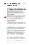
User manual
Kabola B serie
Kabola Heating Systems BV
Placotiweg 1E
4131 NL Vianen (Utr.)
Nederland
Preface
This user-manual is written to enable the safe operation of the B-Series central heating boilers.
The user must read this manual before installation of the boiler and must follow the instructions within
this manual.
Therefore, this manual must be kept with the boiler.
In chapter 2, the safety instructions are detailed, which have to be complied with, when installing and
using the boiler. In other chapters you will find safety instructions, that can be identified in the following
way.
Hint: This gives the user suggestions and advises to facilitate the execution of certain tasks.
Attention: Additional information is supplied to the user, and possible problems are indicated.
Warning: Watch out for possible (life-threatening) injuries.
For any remarks, wishes or omissions you can contact Kabola Heating Systems. We also welcome
any remarks to improve this manual. We wish you a lot of pleasure from your purchase.
Kabola Heating Systems
Placotiweg 1E
NL 4131 NL Oudewater
The Netherlands
Phone +31 (0)347-320030
Fax
+31 (0)347-355688
Web: www.kabola.nl
E-mail [email protected]
Vianen, oktober 2009
© 2005 Kabola Heating Systems
Copying of (parts of) this manual, is only allowed with written consent of Kabola Heating Systems.
User manual Kabola B-serie, oktober 2009
2
Contents
Preface
Contents
1.
Introduction
1.1
General Introduction.
1.2
Range application
1.3
Product description
1.4
Technical specifications
2.
Safety
2.1
General safety
2.2
Safety instructions
3.
Transport and storage
3.1
Transport
3.2
Storage
4 Installing and preparing for first use
4.1
Installation
4.1.1
Fitting the boiler
4.1.2
Connection of the Central heating system
4.1.3
Flue gas outlet
4.1.4
Electrical installation
4.1.5
Filling the central heating system
4.1.6
Mounting the burner
4.1.7
Connecting the oil filter and oil burner
4.2
Starting your system
5 Operating the boiler
6 Cleaning and maintenance
6.1
Points of attention
6.2
Cleaning and maintenance.
7 End of life of the boiler
Appendix A Technical specifications
Appendix B Parts
Appendix C Electrical diagram B8-B70 230V
Appendix D Electrical diagram B80-B100 230V
Appendix E Electrical diagram B8-B45 24V
Appendix F Troubleshooting
Appendix G CE-declaration.
2
3
4
4
4
4
4
5
5
5
6
6
6
6
6
6
7
7
8
9
10
11
12
12
12
12
13
13
14
15
16
17
18
19
20
User manual Kabola B-serie, oktober 2009
3
1.
Introduction
1.1
General Introduction.
Congratulations with your purchase of this Kabola boiler. This user-manual covers the B-Series central
heating boilers. The B-Series central heating boilers cover a wide range of boilers with a broad range
of application. By purchasing this boiler you have acquired a product, which is of high quality through
the application of the latest European standards and directives.
1.2
Range application
The B-Series boilers are designed to generate heat for the heating of water for a central heating
system. The dimensions of the rooms to be heated, have to be taken into consideration.
These boilers are not designed for direct heating of the rooms in which they are installed.
1.3
Product description
The B-Series boilers heat the central heating water by means of a pressure jet burner, which is
installed on front of the boiler. The standard boilers operate from a 230 volt AC Supply. Boilers up to
type B45 can also be supplied to operate on a 240 volt DC Supply. All B-Series boilers work in the
same way, the only difference is the dimensions and the capacities of the boilers (see also the
technical specifications in Appendix A).
As fuel, diesel oil or kerosene has to be used.
At special request there is also a model available which operates on petroleum.
1.4
Technical specifications
The most important technical specifications are listed on the plate on the front of the boiler. More
technical details are listed in Appendix A.
User manual Kabola B-serie, oktober 2009
4
2.
Safety
In this chapter we emphasise the safety-related points for operating the boiler.
2.1
General safety
Warning: Although Kabola Heating Systems designs and produces its products according to the
current safety standards, it is possible that dangers may occur, which could lead to injuries or damage
to the boiler, if the safety instructions in this manual are not complied with.
The user must:
•
Have read and understood the chapter “safety”
•
Avoid any actions which may lead to hazards to his health or others
•
Avoid any actions which may lead to damage to the boiler.
•
Ensure that the boiler is only used when the boiler is in sound technical condition.
•
Ensure that the safety regulations are observed whilst operating the boiler.
Attention: No alterations to the boilers may be done without the explicit written consent of Kabola
Heating Systems!
2.2
Safety instructions
The safety instructions listed below must be complied with when operating the B-Series boilers.
Measures for a safe installation
•
•
•
•
•
•
Don’t store any flammable and/or gaseous products in the room where the boiler is installed to
avoid explosions and fires.
Install the boiler in a non-humid environment on a firm horizontal base.
Ensure that there is sufficient ventilation in the room where the boiler is installed (See also
4.1.1)
Make sure, before you start connecting the boiler, that the system is disconnected from the
power supply.
Only use multiple-stranded wire for electrical connections.
Don’t change the + pole with the – pole of the battery (for the 24 Volt DC version)
Measures for a safe operation
•
•
•
•
•
•
•
Never change the settings of the burner.
Don’t use any aggressive solvents which may affect the boiler (like gas or turpentine)
Don’t damage the fire bricks.
Make sure that the boiler and burner are checked annually by a skilled expert.
Make sure that before you start any work on the boiler that the system is disconnected from
the power supply.
Make sure that any surplus oil is collected in case of oil spillage.
We advise you to have any maintenance or repairs carried out by skilled experts.
User manual Kabola B-serie, oktober 2009
5
3.
Transport and storage
3.1
Transport
Take following precautions before transporting the boiler:
•
Drain the water from the boiler
•
Uncouple the fuel system
•
Remove the burner (see 4.1.5, replacing the burner)
While transporting the boiler, take following precautions:
•
Don’t damage the boiler, use a blanket to cover the boiler.
•
Transport the boiler lying down on its back
•
For the boiler models B-25 onwards use the hoisting eye to move the boiler. This hoisting eye
is
located below the top of the boiler cover.
3.2
Storage
Take the following precautions when the boiler is stored for a longer period of time:
•
Store the boiler and accompanying parts in a dry place.
•
Dismount the burner
•
Store the boiler standing up.
•
Store the boiler on a firm horizontal base.
4
Installing and preparing for first use
In this chapter you will find directions and hints for a correct placement and fitting of the boiler and
accompanying parts.
Warning:
4.1
Don’t store any flammable and gaseous substances in the room where the boiler is
installed. This is to ensure that no explosions or fires can occur.
Installation
4.1.1 Fitting the boiler
•
•
•
Install the boiler in a dry place.
Install the boiler on a firm horizontal base.
Make sure there is sufficient supply of fresh air in the
room where the boiler is installed (see hint below)
Hint: As a rule of thumb for the ventilation openings, take 2,5
times the diameter of the flue gas outlet.
•
•
•
To avoid movement secure the base of the boiler by
Figure 1
means of spotwelds or with nuts and
bolts.
Keep a minimum distance of 250mm behind the boiler
for the flue-gas outlet (see figure 1)
Use a earthed plug socket for connecting the 230 V AC versions to the power supply.
User manual Kabola B-serie, oktober 2009
6
4.1.2 Connection of the Central heating system
Piping
Take note of the following points, when installing the piping:
•
Install the piping in such a way, that the boiler (cover and dashboard) remains accessible.
•
Provide enough bleeding points in places where air might collect.
Attention: Install a automated bleeding valve near the boiler
Connect the piping to the boiler as follows (see figure 2)
1.
Install the feeding to CH at point A
2.
Install the return of the CH on point C
Hint: Install a shunt with pressure equaliser, when thermostatic
radiator valves are applied.
4.1.3 Flue gas outlet
General
Figure 2
The flue gas outlet is an essential part of your heating installation.
An incorrect flue gas outlet reduces the lifespan of your boiler considerably and has a negative impact
on the efficiency. Remember when installing the flue, that even the best boiler won’t work properly
unless the flue is properly installed.
Warning: Because the flue gas temperature lies between 180 - 240°C, it is advisable to insulate the
flue with heat-resistant material in those parts where contact with human body parts is possible.
For a correct flue gas outlet the following points need to be observed:
•
Use the proper length/diameter dimensions, use a diameter equal to the diameter of the flue
gas outlet on the boiler (see also technical specifications)
•
Use double-walled chimney pipe outside to prevent a rapid cooling of the flue gasses, which
might result in condensation in the chimney.
Hint: When using a existing chimney of a larger diameter than the diameter on the boiler, you can
install flexible piping of the correct diameter inside the existing chimney.
The flue can be installed in several different ways. You must carefully consider under which
circumstances the boiler will be used. For sea going boats and sail boats we advise the installation of
a vertical flue where the angles of the boat may be larger. The following installation examples are most
common.
Horizontal flue gas outlet
It is possible to fit a horizontal flue gas outlet to the boiler. The following points need to be observed:
•
•
When a burner with an after purge cycle is used the maximum allowed length is 6 metres. A
burner without an after purge cycle can be fitted with a maximum flue length of 2 metres plus
the silencer.
Make sure that the outlet is positioned at a sufficient height above the waterline. If this not
possible use a swan neck bend in the pipe as in figure 3.
User manual Kabola B-serie, oktober 2009
7
•
•
•
Use hull flanges for installing the flue
through a hullside.
Don’t use more than 5 elbows of 90°.
Every elbow of 90° is comparable to 1
metre of straight pipe.
When a damper 80x60 is fitted, the length of
the 60 mm pipe may not exceed 1 metre
Vertical flue gas outlet.
This way of installation is preferable for
seagoing boats and sailing boats, while these
boats encounter bigger angles through waves
and while under sail. For this kind of flue gas
outlet, the following are important:
•
Install a proper storm cowl on top of
the chimney (this must stop rain
entering)(figure 3)
•
Install a water trap for boilers bigger
than B17, to trap possible water
caused by condensation. (figure 4)
•
Keep the chimney as vertical as possible.
•
Don’t use more than 5 elbows of 90°.
•
The maximum allowed length is 10 metres.
•
Every elbow of 90° counts as 1 metre.
•
Outside use double walled chimney pipe.
Hint:
Figure 3
To reduce the noise resulting from flames, it is wise to install a silencer in
the horizontal flue and the vertical flue.
Kabola can provide you with all components which may be required for installation
such as:
•
Cowls.
•
Flexible piping.
•
Single and double walled chimney pipes.
•
Wall and deck flanges.
•
Silencers.
•
Water traps.
Figure 4
4.1.4 Electrical installation
Warning: Disconnect the power supply from the boiler before you start
installing the boiler. Only use multiple stranded wire.
Electrical installation 230 Volts AC
When a room thermostat has been supplied with the boiler, take the
following steps:
Connecting the room thermostat (see figure 5 and electrical scheme in
appendix C)
1. Remove the cover of the main connector situated below the
dashboard
2. Remove, if present, the wire between point 1 and 2
3. Connect the wires from the room thermostat at T1 & T2, as
pointed at the sticker in the connector;
Figure 5
Attention: The core diameter of the connections mentioned above must be between 1 and 1,5mm².
The wires should be suitable for the voltage used.
User manual Kabola B-serie, oktober 2009
8
Connecting the circulation pump
1.
Connect the pump to points L1 and N of the connector under the dashboard.
2.
Connect the wires at the circulation pump
3.
Replace the cover of the main connector.
Electrical installation 24 Volts DC
Warning: Never change the + pole with –
pole on the battery (See figure 6).
1.
The connection of the room
thermostat is identical to the connection for the
230 Volts version. Use figure 6 instead of
figure 5.
2.
Connect the circulation pump to points
3 and 4 of the main connector.
3.
The core diameter of the wires to
points 5 and 6 of the connector should
conform to the values in
table 1.
Table 1
Distance to the battery
± 6 metres
± 15 metres
Core diameter
6 mm²
10 mm²
Figure 6
4.1.5 Filling the central heating system
The pressure in the system should:
•
Never be lower than 0,5 bar cold;
•
Never be higher than 2,5 bar hot;
Follow the procedure listed below for filling the CH-system (see figure 7)
1.
Switch off the boiler
2.
Turn the coupling nut below the pressure indicator to loosen it;
3.
Pull the hose connection a little downwards;
4.
Connect the hose with a hose clamp to the connection.
5.
Fill the system slowly with water, until the pressure indicator indicates
a pressure of 2 bar.
6.
Fasten the coupling nut;
7.
Bleed the CH-system
Figure 7
8.
If necessary, fill with water again up to 2 bar of
pressure.
9.
Switch on the boiler and let the pump run for about 5
minutes.
10.
Switch off the boiler.
11.
Check the water pressure, if it is too low, repeat steps
5 through to 10;
12.
Remove the hose.
Hint: The CH-system can be filled with cooling fluid, suited
for CH-systems (pH-value 8.5).
Bleeding the circulation pump
User manual Kabola B-serie, oktober 2009
Figure 8
9
The circulation pump can only be bled when the electrical circuit is connected, because this has to be
done with a running pump.
Follow the points listed below to bleed the pump (see figure 8):
1.
Check if the rotor can rotate without problems by
turning the pump by hand (see manual
pump)
2.
Loosen the screw on front of the pump ½ to 1 turn
with a screw-driver.
3.
Fasten the screw when water comes out of the opening.
4.
The pump is bled.
Attention: when locking pump couplings which are supplied with the boiler, the adjusting grooves
must point towards the pump (see figure 9)
4.1.6 Mounting the burner
Hint: Check if the inspection opening on the mounting plate can be reached. If this is
not the case the mounting plate can be turned 180° to reach the opening easier. For a
B12 you need to saw an extra piece off the flange.
The mounting of the burner is done in the following way;
1.
Place the nut for the flange bolt in the dedicated position and place the gasket.
2.
Mount the flange with the 4 supplied M8-bolts hand tighten on the mounting
plate. The arrow on the flange should point upward.
Figure 9
Hint: Smear some sealant in the crack in the flange to
seal.
3.
3.1
Measure and set the distance from the back of the
gasket, mounted behind the mounting plate, to the
front of the flange using the table below and figure
10.
Boiler type
B25-B35-B45
B55-B70-B80-B100
3.2
3.3
4.
5.
6.
Distance in mm
155
160
Scribe the distance on the pipe;
Push the burnerpipe gently in place up to the scribed
position (see figure 10)
Lift the burner a little (figure 11) according to 7A;
Fasten bolt 7 (figure 11) on the flange to clamp the burner;
Fasten the hand tightened bolts on the mounting plate.
Figure 10
Attention: Take care that the burner pipe is not damaged during installation. Repairs to the burner
pipe are very expensive and don’t fall under warranty.
User manual Kabola B-serie, oktober 2009
10
4.1.7 Connecting the oil filter and oil burner
Figure 11
To connect the filter to the boiler follow the procedure below
(see also figure 11)
1.
Remove the burner cover (1);
2.
Connect the oil pump (2) to the oil-filter (3), using
the included fuel hoses. Make sure that
the flow directions on the pump comply with those on
the filter.
3.
Connect the fuel line from the tank to the filter (5A).
The fuel line must have a outer diameter of
8mm
and must be made from copper or steel.
The fuel has to be connected directly to the oil tank.
Correct functioning of the burner can not
be
guaranteed when a fuel manifold or T- connection is
installed.
4.
Connect the plug (4) from the boiler to the
burner.
Hint: When the oil tank is situated below the boiler or when
the oil supply line comes from below the boiler, it is advisable
to use a self bleeding oil filter. This prevents unnecessary
malfunctioning of the burner
(see figure 12).
Figure 12
User manual Kabola B-serie, oktober 2009
11
4.2
Starting your system
When everything is connected follow procedure below:
1.
Connect the boiler to the power supply, the earthed outlet for the 230V AC version and the
battery for the 24 V DC version.
2.
Switch the boiler on with the on/off switch on the dashboard. The lamp in the switch will
indicate that the system is active. This lamp is not present in the 24 V DC version.
3.
Set the required boiler temperature between 55 and 90°C using the boiler thermostat.
4.
Set the room thermostat so that it is switched on. (See manual of the room thermostat)
5.
Start the oil burner (figure 11)
5.1
Open the valve of the fuel tank (5)
5.2
Open the valve on the oil filter (5A)
5.3
Install the bleeding hose (3C) on the bleeding opening of the filter
5.4
Start the oil burner.
5.5
The burner switches on, when the burner is fitted with a pre-heating element, this will
take 1,5 minutes.
5.6
Open the bleeding valve on the oil filter.
5.7
Check if oil is coming out of the hose.
5.8
Check all oil connections for leakage’s.
5.8.1 When the burner won’t start, the control light (8) will light.
5.8.2 close the bleeding valve (3B) on the filter.
5.8.3 Wait approximately 3 minutes.
5.8.4 reset the burner by pushing button (8) and return to 5.4 (repeat if necessary)
5.9
Close the bleeding (3B) when only oil and no bubbles come out of the hose.
Attention: The oil burner is tested by the manufacturer, not adjusted. The adjustment of the burner
has to be done by an experienced installer, because this requires expert knowledge. To be eligible for
warranty, the boiler has to be adjusted by an approved installer. Contact Kabola Heating Systems or
your importer to make an appointment.
Never adjust the burner using your own initiative.
A correctly adjusted burner shows a clear white flame, which is visible through the inspection opening
(6)
5
Operating the boiler
When the boiler has been started and adjusted according to 4.2, operation of the boiler is very simple.
The required temperature is set with the room thermostat, which regulates the boiler. The operation of
the thermostat is explained in the manual of the room thermostat.
If problems arise with the operation of the boiler, you will find a list of possible problems and solutions
in Appendix D.
6
Cleaning and maintenance
6.1
Points of attention
Spare parts must be ordered through your importer dealer or from Kabola Heating Systems. For
warranty purposes only original spare parts may be used. When ordering spare parts, mention the
type of the boiler and its serial number. Kabola Heating Systems will then be able to deliver the correct
parts. In Appendix B, the main spare parts are listed.
User manual Kabola B-serie, oktober 2009
12
6.2
Cleaning and maintenance.
Warning: Maintenance and repairs should only take place when the boiler is switched off this is
because the boiler might start unexpectedly. Take the plug from the wall socket. Disconnect the
power supply for the 24 Volt version.
Warning: Maintenance and repairs may only be performed by personnel, who have read and
understood the information in this manual, preferably an expert installer or mechanic from Kabola.
Every week
•
Drain the water from the water trap if installed
Every year
1.
2.
3.
4.
5.
Clean the boiler
1.1
Remove the burner (see § 4.1.5);
1.2
Remove the burner mounting plate from the boiler;
1.3
Remove the top cover of the boiler, be careful not to damage the earthing wire;
1.4
Remove the insulation.
1.5
Remove the 4 bolts on the boiler top;
1.6
Remove the boiler top;
1.7
Clean the inside of the boiler, using a stiff brush;
1.8
Clean the space between the pipes with a thin metal strip;
Attention: Don’t use any aggressive solvents like thinner or gasoline.
1.9
Clean the boiler with a vacuum cleaner;
1.10
Replace the boiler top, if necessary use a new gasket;
1.11
Replace the 4 bolts and fasten these;
1.12
Replace the insulation;
1.13
Replace the top cover of the boiler, make sure the earthing wire is fitted correctly;
1.14
Replace the burner mounting plate and remount the burner (see § 4.1.5);
Clean the chimney;
Clean the watertrap if installed;
Change the oil filter element;
Clean the burner (see manual of the burner)
Hint: Kabola Heating Systems has a standard set with replacement parts for the yearly maintenance
(see Appendix B)
Attention: The old oil filter element has to be processed as chemical waste.
7
End of life of the boiler
When the boiler will be scrapped, take note of the points listed below.
•
Process the oil filter and the oil hoses as chemical waste.
•
Separate the metal from the plastic parts and dispose them separately.
•
Process any excess oil in an environmentally friendly way.
•
Transport the boiler according to the instructions in chapter 3.
•
Recycle this manual
User manual Kabola B-serie, oktober 2009
13
Appendix A Technical specifications
Type
A
B
C
D
E
F
G
H
I
J
Flue gas ø
Fluegas temp °C
C.H.-connection
IP-value
Burner
230 V
24 V
Nozzle 60°
Nom. Capacity kW min
max
Max oil consumption kg/h
Testpressure in bar
Operating pressure in bar
Weight in kg
Water volume in l
Temperature control range
Isolation thickness in mm
Fuel
Burning efficiency in %
Waterside efficiency %
Standby loss
B-25
970
455
115
466
283
388
70
385
396
753
100
180-220
5/4”
B-35
970
455
115
468
284
491
70
385
503
754
125
180-230
1½”
2-B012
3-C015
0.85
19.7
29
3.3
5
3
118
18
35-90
50
2-B013
3-C016
1.00
29
40.7
3.7
5
3
140
23
35-90
50
92
89
92
89
B-45
970
445
125
488
284
580
70
385
593
754
150
180-230
1½”
B-55
970
485
125
498
384
697
70
385
708
759
150
180-240
2”
50-11
2-B014
B-70
1165
487
508
314
699
70
385
708
961
180
180-240
2”
2-B014
2-B016
3-C017
1.25
1.50
1.75
40.7
51.1
63.9
52.3
63.9
81.4
5.2
6.5
7.5
5
5
5
3
3
3
155
178
270
26
36
55
35-90
35-90
35-90
50
50
50
HBO 1, HBO 2, diesel of gasolie
92
91
91
89
88
88
3%
User manual Kabola B-serie, oktober 2009
B-80
1165
487
508
314
839
70
385
858
963
180
180-250
2”
B-100
1165
488
498
314
1050
70
460
1058
963
200
180-260
2”
2-B017
1.75
74.4
93
8.4
5
3
309
68
35-90
50
2.00
93
116.3
10.3
5
3
445
82
35-90
50
91
88
91
88
14
Appendix B Parts
Listed below you will find the most important parts of the boilers. These parts can be ordered from your
importer or Kabola Heating Systems, stating type and serial number.
The numbers refer to the image.
1 Boiler top cover
2 Insulation
3
4
5
6
7
8
Cover of boiler
Boiler gasket
Dashboard
Thermometer
Boiler thermostat
On/off switch
9 Maximum
thermostat
10 Main connector
11 Pump coupling
12 Circulation pump
13 Seal
14
15
16
17
18
19
20
21
22
23
Fibreglass- or
rock wool
thickness
App. A
No lamp in 24 V
DC version
1” or bigger
Two 1¼” or
bigger
Knee inner- x outer Different per
thread
type (1x1, 1¼x1
or 1½x1)
Pressure valve/
pressure gauge/ fill
drain cock
T-connection
Only for B-12
1”x½”x1”
Fire inspection
opening
Oil burner
Comes with
flange and
gasket
Burner mounting plate
Gasket for mounting plate
Boiler cover side/front
Boiler cover back
Oil filter (not shown in picture)
24 Room thermostat (not shown in picture)
Following spare parts are available.
25 Nozzle
max. 25µm , Pmax 6 bar
max. capacity 200 l/hour, total ± 6000 l.
max. vacuum -0,5 bar
Imit TA3
See Appendix A
For the yearly maintenance Kabola Heating Systems has compiled a set of spare parts often used
during maintenance.
26 Service set comprising of 4+23+25
User manual Kabola B-serie, oktober 2009
15
Appendix C Electrical diagram B8-B70 230V
User manual Kabola B-serie, oktober 2009
16
Appendix D Electrical diagram B80-B100 230V
User manual Kabola B-serie, oktober 2009
17
Appendix E Electrical diagram B8-B45 24V
User manual Kabola B-serie, oktober 2009
18
Appendix F Troubleshooting
Listed below you will find a list with possible problems, their reasons and solutions.
When you encounter problems not listed, you should contact your dealer. Never try solve problems
on your own.
Problem
Burner won’t start
Possible reason
Oil supply interrupted
Power supply interrupted
Burner stops
Burner starts pulsing
Burner shows error
Boiler does not react to
thermostat
Water is not pumped
Flame protection dirty (photo
cell)
Flame protection defect (photo
cell)
Flue glass flow interrupted
Boiler dirty
Oil supply interrupted
Nozzle defect
Possible solution
Bleed the oil filter
Change contaminated filter
element
Fill the oil tank
Check the fuses
Check the power supply
Reset burner
Clean glass of flame protection
Replace flame protection
Clear chimney opening
Clean boiler
See above
Replace nozzle
Reset burner
Low voltage
Check voltage level
Oil supply interrupted
See above
Wire in main connector has not
Remove wire from main
been removed (room thermostat) connector
Boiler thermostat incorrect
Adjust boiler thermostat
adjusted
Battery of room thermostat
Replace battery
empty
Pump couplings are closed
Open pump couplings
Pump not connected to power
Connect pump
supply
Rotor of pump is stuck
Turn pump with your hand (see
manual pump)
User manual Kabola B-serie, oktober 2009
19
Appendix G CE-declaration.
User manual Kabola B-serie, oktober 2009
20