1
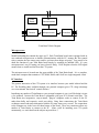
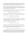
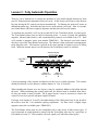
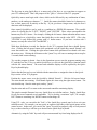
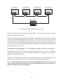
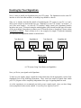
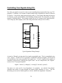
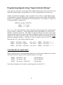
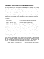
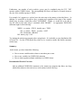
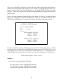
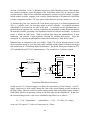
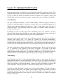
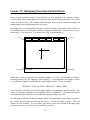
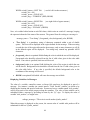
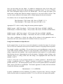
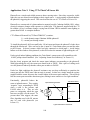
Controlling Your Signals Using TCL
Now that your signals are wired, it’s time to start controlling them automatically from your TCL
programs. To illustrate, we’ll consider a simple example using a Signalman to control a collection
of signals: a 3-color block signal portraying track status, a 2-color signal indicating the direction
of a turnout, a grade crossing flasher, and a blinking warning beacon. The wiring for our simple
example is illustrated below. This example assumes the use of Common Anode signal hardware.
Your wiring may differ slightly (refer to the wiring instructions in the previous section).
V+
V-
“block1”
G
Y
1
2
3
“sidingA”
R
G
4
5
“crossing”
6
7
“beacon”
9
Signalman
R
10
11
12
13
14
15
16
8
Typical Signalman Wiring Example
As usual, we’ll begin by giving each of our signals a meaningful name. This is accomplished using
a new “Signals:” section of our TCL program. In addition to naming our signals, we’ll also need
to let tbrain know how many controllers each signal uses. To do so, simply list the number of
controllers, between braces, following the signal’s name. For our example above, the “Signals:”
section of our TCL program might be:
Signals: block1(3), sidingA(2), crossing(2), beacon(1), spare(8)
Note that we’ve only used 8 of our Signalman’s 16 controllers. As with the Train Brain’s
controllers and sensors, we must designate any unused signal controllers as “spare”. This lets
tbrain keep precise track of which signals are wired to which of the Signalman’s controllers.
50