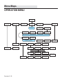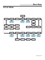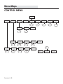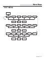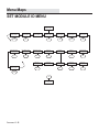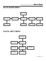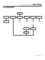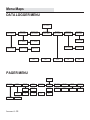
1
First Edition
JULY 1998
Revised: May 2002
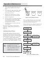
Copyright
© RK2 Systems, Inc.., 1994-2002. All
rights reserved worldwide. No part of
this publication may be reproduced,
transmitted, transcribed, stored in a
retrieval system or translated into any
language in any form by any means
without the written permission of
RK2 Systems, Inc..
Table of Contents
1. INTRODUCTION
How the RK2 System Controller Works ........................................ 1-3
User Guide Features .................................................................. 1-4
Quick Reference Menu Map ........................................................ 1-4
Monitoring Capability ................................................................. 1-4
Flash Memory Architecture ........................................................ 1-5
Status Lights .............................................................................. 1-5
Infrared Printer Port ................................................................... 1-6
Powering the System Controller .................................................. 1-6
Control Capability ....................................................................... 1-7
2. INSTALLING THE COMPONENTS
Step 1. Mount the System Controller .......................................... 2-4
Step 2. Installing the Temperature, pH, and ORP Probes ............. 2-6
Step 3. Install the Digital Input Hardware ................................... 2-9
Step 4. Install Optional X-10 Control Module ............................. 2-11
Step 5. Install and Address Optional Satellite Module(s) ............ 2-11
Step 6. Install Communications Equipment .............................. 2-13
Step 7. Power Up the System Controller .................................... 2-17
Step 8. Install the 9-Volt Backup Battery Pack (Optional) ........... 2-18
3. PROGRAMMING THE SOFTWARE
Overview of the System Controller Menus .................................. 3-2
Using the Menu Map—An Example ............................................. 3-4
i
Table of Contents
Initial Software Setup ................................................................. 3-4
Step 9. Set the System Clock ...................................................... 3-4
Step 10. Enter the Protective Password ....................................... 3-6
Step 11. Set the Noise Filter Control ........................................... 3-6
Step 12. Select the Conductivity Temp Compensation Settings .. 3-7
Step 13. Select a Conductivity Range .......................................... 3-7
Step 14. Select a Temperature Scale. ......................................... 3-8
Step 15. Enter Setpoint and Range Values .................................. 3-8
Step 16. Entering Alarm Range Values ..................................... 3-12
Step 17. Set up Digital Input Alarm ........................................... 3-15
Step 18. Set up the Lighting System ......................................... 3-15
Step 19. Set up the WaveMaker System ..................................... 3-16
Step 20. Set Up System Hold Control ......................................... 3-16
Step 21. Assign System Control Addresses ................................. 3-17
Step 22. Set Up the Communication Software ............................ 3-18
Step 23. Enable System Control ................................................ 3-21
Step 24. Test the System Configuration .................................... 3-22
4. OPERATION AND MAINTENANCE
Daily check list ........................................................................... 4-2
Cleaning the Probes .................................................................... 4-3
Calibrating the Probes ................................................................. 4-4
Replacing a Probe ........................................................................ 4-8
Conducting a System Test ........................................................... 4-8
Changing a Control Address ........................................................ 4-9
Operating the Infrared Printer ..................................................... 4-9
ii
Table of Contents
5. SETTING UP AQUAWEB FOR WINDOWS 95
AquaWeb - Introduction .............................................................. 5-2
Step1-Configuring Windows Com port setting to support AquaWeb 5-4
Step 2 - Installing AquaWeb on your PC ....................................... 5-5
Step 3 - Starting and configuring AquaWeb ................................. 5-7
6. ADLOADER - Upgrading the H2O/S software
Upgrading the H2O/S software in your RK2 Computer ................. 6-2
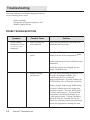
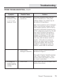
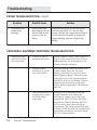
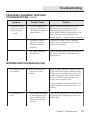
7. TROUBLESHOOTING
Probe Troubleshooting ................................................................. 7-2
Peripheral Equipment Response Troubleshooting ......................... 7-5
Modem/pager Troubleshooting .................................................... 7-6
AquaWeb Troubleshooting ........................................................... 7-7
APPENDICES
Appendix A: Menu Maps
Appendix B: Understanding Water Quality
Appendix C: Conversion Tables
Appendix D: Product Warranty
This manual is available in an Adobe “pdf” format from our web page at
http://www.rk2.com. For the latest information, electronic updates to
this documentation and other technical information, we recommend
that you check with us regularly.
RK2 Systems, Inc.
421A Andreasen Drive
Escondido, CA 92029
(760) 746-7400
http://www.rk2.com
iii
Chapter
1
Introduction
Introduction
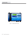
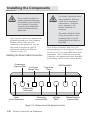
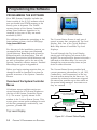
Figure 1.1 The RK2 System Controller
1-2
CHAPTER 1: INTRODUCTION
Introduction
HOW THE RK2 SYSTEM
CONTROLLER WORKS
Congratulations on your purchase of the
most sophisticated, yet easy-to-use aquatic
environment controller on the market today.
Designed with a powerful INTEL™ microprocessor, your System Controller™ controller
includes the following features:
•
Continuous monitoring of conductivity,
water temperature, pH and oxidation
reduction potential (ORP).
•
H2O/S software with menu-driven
programming environment.
•
Aux. Input supports power failure, water
level or pressure alarming.
•
FLASH memory that makes upgrading
your System Controller with new H2O/
S software a simple task.
•
Local audible alarm or optional remote
dial-up pager alarm capability.
•
Parameter control capability for management of peripheral equipment such
as pumps, and lighting.
•
Powerful datalogging capability that
holds up to 7-days of probe data.
™
•
Operates on 9V AC or on an optional 9V
DC battery backup.
•
optional X-10 support for up to 255
control outputs.
•
An infrared Data Port that supports an
optional hand-held HP printer for data
reporting and graphical analysis.
•
Single communication port supporting
both direct connection to a PC or remote
modem communication.
•
AquaWeb™ Remote Access—Our latest
software product that allows you to
communicate with your System Controller, perform advanced graphical
analysis of current and historical
data—from any Windows 9x/NT/2000
PC. The standard version of AquaWeb
is available for no cost through our
WEB site at:
HTTP://www.RK2.com
Single User and Multi-User versions of
AquaWeb are available for additional
cost through your dealer.
Until now, performing even the simplest
functions with a controller required technical
or electronic expertise. The System Controller makes maintaining the optimum aquatic
environment easy.
The System Controller is constructed with
only the highest quality components. The
heart of the System Controller is an INTEL
microprocessor which manages all of the
activities of the controller. All information
☞
Note
!
CAUTION
The helpful Notes logo
highlights items which will
save you time and effort, and
increase your understanding of
the System Controller operation.
The CAUTION logo highlights
items which are critical to
safety or which may cause the
System Controller to malfunction or become damaged.
CHAPTER 1: INTRODUCTION
1-3
Introduction
gathered by the controller is processed
digitally. The System Controller Architecture
includes Digital Signal Processing (DSP)
hardware and software that provides accurate and repeatable readings over the life of
the System Controller. In addition, the
microprocessor design provides unsurpassed
flexibility, as reflected by the variety of
software options that are available for the
System Controller.
We recommend that all users review this
information before proceeding with Chapter
2, Installation and Software Programming.
This User Guide includes several quick
reference features, including Notes, Cautions
and a Quick Reference Menu Map.
QUICK REFERENCE MENU MAP
RK2™ is committed to building products that
meet world class standards of quality and
workmanship. If you have any questions
regarding the use of this product, RK2
provides hotline service through the Technical Support Group. They can be reached via
the Internet at: [email protected]
The primary source for technical and other
useful information about the System Controller, including the latest release of this
User Guide in Adobe™ “PDF” format, can be
found on our Web Page:
http://www.RK2.com.
Our Web Page contains current software
releases and always reflects the latest information about our products, so we suggest that
you visit it frequently.
USER GUIDE FEATURES
The System Controller User Guide is
presented in five chapters: Introduction,
Installation, Programming, Operation and
Maintenance, and Troubleshooting.
In Chapter 1, we provide a basic overview of
the System Controller and its capabilities.
1-4
CHAPTER 1: INTRODUCTION
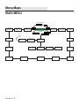
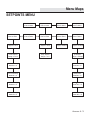
The laminated Menu Map included with your
System Controller summarizes the H2O/S
software menu structure. Post it in a
convenient spot for quick reference. For
more detailed menu maps, refer to Appendix
A.
MONITORING CAPABILITY
The Standard System Controller software
provides for monitoring, control, and alarm
capabilities. The four water quality parameters monitored are:
•
Conductivity
•
Temperature
•
pH
•
ORP
In addition to the four parameters the
System Controller also provides an aux.
input which can be configured to provide a
digital input for power failure detection, or
water level alarming.
Probes connected to the bottom of the
System Controller gather information and
Introduction
relay it to the System Controller for processing and display on the screen.
The System Controller is programmed using
a membrane keypad on the face of the unit.
Directional arrows on the keypad are used to
move horizontally across a given menu level.
The “Enter” key is used to move down the
menu map or to make a selection.
Once in the submenus, if there is no activity
for ten minutes in most menus, the System
Controller LCD display window will return to
the Current Status Display. Settings
entered up to that time will be saved. When
not in programming mode, current status
information gathered by the probes is shown
on the System Controller LCD Display
Window.
System Controller can be found on the RK2
WEB page:
http://www.rk2.com
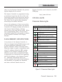
STATUS LIGHTS
Parameter Status Lights
Parameter Status Lights
No Light. (Parameter is within setpoints and no
dosing required, OR control system is not activated.)
Conductivity
Solid Green. (System is dosing to lower
conductivity value.)
Flashing Green. Dwell State. (Will read
conductivity again after dwell time is complete.)
Solid Red. (System is Dosing to raise conductivity
value.)
FLASH MEMORY ARCHITECTURE
A key feature of the System Controller is
that it is designed using FLASH memory and
a special application embedded in the
System Controller called a bootstrap loader.
When the loader is used in conjunction with
other PC software offered by RK2, routine
updates to the System Controller H2O/S
software can be easily accomplished. Refer
to Appendix D for instructions on upgrading
the H2O/S software in the System Controller. Additional Information about the
current revision level of the H2O/S software,
the availability of AquaWeb for Windows,
and other technical details about the
Flashing Red. Dwell State. (Will read conductivity
again after dwell time is complete.)
Temperature
Solid Green. Chiller On. (Current temperature is
too high.)
Flashing Green. Chiller Dwell State. (Dwell time to
prevent compressor burn out.)
Solid Red. Heater On. (Current temperature too
low.)
pH
Solid Green. (CO2 is Dosing to lower pH.)
Flashing Green. Dwell State. (Will read pH again
after dwell time is complete.)
Solid Red. (pH buffer is dosing to raise pH.)
Flashing Red. Dwell State. (Will read pH again
after dwell time is complete.)
ORP
Solid Red. (Ozone is dosing to raise ORP.)
Figure 1.2 Parameter Status Lights
CHAPTER 1: INTRODUCTION
1-5
Introduction
The Parameter Status Lights located on the
face of the System Controller indicate
whether a system is operating within it’s
preset limits or a control system has been
activated. A status light lit red indicates
that the system detected a low condition, a
green light indicates a high condition. A
summary of Parameter Status Lights is
given in Figure 1.2.
System Status Light
The System Status Light located at the
bottom of the System Controller indicates
System Status Lights
Solid Green. Operating properly and available
for data entry.
Flashing Green. Busy processing data.
Flashing Green/Orange. Sending commands
through the power line to the Satellite Modules.
Flashing Red. Controller hardware failure. Unplug
the Octopus controller and call Aquadyne
customer service.
Figure 1.3 System Status Lights
the general condition of the System Controller operating system. Figure 1.3 summarizes the System Status Lights and their
meaning.
Infrared Printer Port
The infrared printer port located at the bottom left of the face of the System Controller
is standard. This port provides access for
the optional infrared data-log reporting feature. Using the Infrared Printer (optional)
data collected by the System Controller can
1-6
CHAPTER 1: INTRODUCTION
be printed out in a variety of formats, including the current data, the high and low
points of data collected within the last 24
hours, 48 hours, or 1 week. Temperature,
pH, and ORP can be graphed. Conductivity
will be added in a future release of H2O/S
software
Powering the System Controller
Primary power for the System Controller is
provided by an A/C wall-mount transformer.
A UL, CSA or CE approved transformer rated
for the correct input voltage (110V or 220V)
is used to power the System Controller. The
output voltage to the System Controller
must be 9V AC.
The System Controller design incorporates
FLASH Memory, RAM, and a battery backedup real-time clock. Should power be lost,
none of the parameter setpoints, or configuration data will be lost. However, during
a power failure, data in the datalog will be
erased.
Backup power is provided by either of two
methods:
!
CAUTION
UPS power supplies have built in
noise and surge suppression and
WILL block X-10 control signals.
Do not plug the X-10 power line
interface module into a power
outlet that is powered by the
UPS, unless all the X-10 control
modules are also powered by the
UPS as well.
Introduction
!
CAUTION
Your System Controller is a
precision laboratory instrument that could be damaged
by unexpected power surges
or fluctuations.
The use of a quality surge
protection device is highly
recommended, and is required
to preserve your warranty.
However, DO NOT USE a surge
suppressor between an
System Controller power line
interface and a control
module.
•
!
CAUTION
The proper and reliable functioning of the System Controller and
the X-10 control system is
dependent on the proper installation of the System Controller,
the X-10 Power Line Interface,
and each Control Module. Other
electrical devices, such as
motors, ballasts, and dimmer
switches produce electrical
interference that may affect
X-10 signaling. Refer to Chapter
5, Peripheral Device Troubleshooting, for further details.
An optional 9-Volt backup “battery
pack” specially designed by RK2.
System Controller and give it the capability
for parameter control as well as monitoring.
• An optional UPS Backup Power System With the purchase of the optional X-10
(Uninterrupted Power Supply). (The A/C
power line interface and one or more control
wall-mount transformer is plugged into
modules, a wide variety of monitoring and
this system.)
control features are automatically activated.
The backup battery-pack is an inexpensive
The System Controller control system has six
means of providing about 45 minutes of
basic components, as shown in Figure 1.4:
backup power during a power failure. While
operating from the battery pack, the System
• The System Controller
Controller will continue to operate normally
until the battery is exhausted.
• Wall Mount Power Supply
If a UPS system is used as a backup power
• Probes
source, it may be purchased from RK2. A
• The X-10 Power Line Interface
UPS backup is a good idea if you require
more than 45 minutes of backup power, or if
• One or More Control Modules
you wish to backup other critical peripheral
• A Modem
or communications equipment such as a
pump, a bio-filter or a modem for example.
(Note: The modem, the X-10 power line
Note however, that the duration of backup of interface, and the control modules are
the UPS is reduced by the addition of such
options.)
equipment.
Control Capability
H2O/S software is used to program the
CHAPTER 1: INTRODUCTION
1-7
Introduction
Control Using X-10 Management
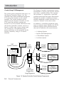
The probes gather information and relay it to
the System Controller (Figure 1.4). The
controller then sends commands through the
X-10 power line interface to the control
modules. The control modules receive
signals from the System Controller via the
X-10 power line interface turning the
devices on or off as needed. Each device that
the System Controller controls, such as a
heater or chiller, has its own control module. As many as 256 addresses and a
variety of devices can be controlled by the
System Controller, using X-10 control
modules
RK2
System Controller
Modem
The System Controller incorporates several
mechanisms to protect your aquatic environment from controller failure. For example,
the controller is engineered to overcome
problems associated with power fluctuations
through the periodic re-sending of control
module commands to make sure that a X-10
control is “latched” in the correct state.
In addition to controlling peripheral equipment to maintain water quality, the H O/S
software supports other optional features
that can be enabled on the control menus:
2
•
A Lighting System
•
System Hold Management
•
A WaveMaker System
•
An Alarm System
X-10
Control
Module
X-10
Power
Supply
Octopus
Satellite
Module
Device
(E.g. Pump)
Octopus
Satellite
Module
Device
(E.g. Chiller)
Octopus
Satellite
Module
Device
(E.g. Heater)
Surge
Suppressor
Probe Cables
Power
Transformer
Plugged Into
Surge Suppressor
Figure 1.4 System Controller Control System Components
1-8
CHAPTER 1: INTRODUCTION
Introduction
Example Lighting Scheme
Timer 1 is for the fluorescent lamps.
These lamps are the first lights to come
on in the morning and the last to go off
late at night.
Timer 2 is for the metal halide lamps.
To approximate the sun rising, these
lamps come on in the late morning and
go off in the late afternoon.
Timer 3 is for an additional halide
lamp. This lamp will come on for about
one to two hours at noon to simulate
the midday sun.
Timer 4 is for a red bulb during the
night to allow observation of nocturnal
creatures that come out when the lights
are out, and or moonlight simulation.
If you have the 16-channel Lighting
System and are not using all 16 channels, you can use the additional channels to control other devices.
Figure 1.5 Example Lighting Scheme
Each of these features is described in
following sections.
Lighting System
(4-Channel or Optional 16-Channel)
The lighting control feature allows the
System Controller to control your system
lighting. The lighting system will support up
to 16 independent lighting times per 24
hours. Each channel has one ON and OFF
time per 24-hour period. The System
Controller comes standard with 4-channel
lighting software. A optional 16 channel
system is available as an option.
With separate lighting timers, there is a
high degree of flexibility in setting up your
lighting system. For example, in your
application you may wish to use a combination of metal halide, fluorescent, and
incandescent lighting. And each lighting
system may require a dedicated ON and OFF
time. The System Controller lighting system
can manage these and other varied timing
needs under software control. (Figure 1.5).
System Hold
The H2O/S system hold software is a
feature designed to aid in the feeding of fish
and invertebrates. When the System Controller is put into feed mode, all systems,
except the Lighting and WaveMaker systems, are shut down for a period of time
selected by the user. At the end of the
specified time (up to 60 minutes) all systems are turned back on and will restart
within 5 minutes. If desired, the system
hold option may be turned off by setting the
feed time to 0 minutes. The System Controller will then no longer prompt you to enter
the system hold mode.
WaveMaker System
The H2O/S Dual Channel WaveMaker
software feature allows System Controller to
control two independent wave or surge
generation systems. Each system supports
two pumps which are driven by Control
CHAPTER 1: INTRODUCTION
1-9
Introduction
Modules. The cycle time for each pump is
selected by the user, from 1-999 minutes
(over 16 hours).
Alarm System
The H20/S alarm system software provides
visual and audible notification in the event
that a monitored parameter exceeds the user
defined range. The optional pager alarm
software upgrade used in conjunction with a
modem provides remote alarm notification via
a digital pager.
1-10
CHAPTER 1: INTRODUCTION
Chapter
2
Installing
the
Components
Installing the Components
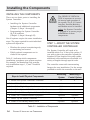
This Chapter will provide you with simple
step-by-step instructions to lead you through
the installation process. But before
continuing...
STOP–READ THIS FIRST
!
CAUTION
DO NOT ALLOW CONTROLLER
TO GET WET!
Your System Controller can be located
in any dry location. The controller is not
waterproof and cannot be submerged,
permitted to get wet or exposed to high
humidity. To avoid splashing the unit,
install it properly as described in this
chapter.
AVOID DANGEROUS
OPERATING CONDITIONS
Do not operate the System Controller
under any of the following conditions:
2-2
•
With wet hands.
•
If you are standing in water.
•
If the AquaNode Controller is wet.
•
If there is salt creep on the box.
CHAPTER 2: INSTALLING THE COMPONENTS
KEEP pH AND ORP PROBE
TIPS WET AT ALL TIMES
To prevent loss of accuracy in the pH
and ORP probes, be sure to keep the
tips wet at all times. NOTE: Do not
completely submerge probes. Refer to
probe installation procedures (Step 2) in
this chapter for more information.
INSTALL ALL ELECTRICAL
CORDS CORRECTLY
Always take care when using electricity
around water. To prevent water from
running down the cord of an aquarium
device, always use a drip loop as shown
in Figure 2.1. To create a drip loop, make
sure that the cord extends below the
outlet so that any runoff will not enter
the outlet or the device. Also, the
System Controller and ALL other aquatic
environment devices should be plugged
into a GFCI outlet.
If you are not familiar with installation of electrical equipment, it is
strongly recommended that you hire
a licensed electrician.
Installing the Components
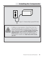
Figure 2.1 • Protective Drip Loop and GFCI Outlet
!
CAUTION
In addition to a surge suppressor, a Ground Fault Circuit Interrupter (GFCI) should be part of you installation. A GFCI is a sensitive device which immediately cuts off the electricity flow when an
electric current leak is detected. All devices that are part of the
System Controller system should be connected to a GFCI
protected circuit. If you do not have one installed already, you
should purchase one. They are inexpensive and are available at
any electronics or hardware store. Don’t wait, a GFCI can save
your life!
CHAPTER 2: INSTALLING THE COMPONENTS
2-3
Installing the Components
INSTALLING THE COMPONENTS
There are two basic parts to installing the
System Controller:
•
Installing the System Controller
hardware and additional components
(Chapter 2, Steps 1 through 8).
•
Programming the System Controller
(H2O/S) software
(Chapter 3, Steps 9 through 25).
Not all systems require the same installation
steps. The steps required for each individual
system will depend on:
•
Whether the system is monitoring only
or monitoring and control.
•
Which optional components are included in the system.
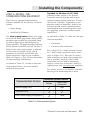
Table 2.1 indicates which components
installation procedures your system requires.
For example, for Monitoring Only systems,
only installation steps 1, 2, and 7 would be
required.
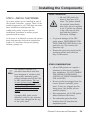
The ORDER OF INSTALLATION is important to successful startup and operation of
the system. The X-10 Control
Interface, Satellite Modules,
and Modem must be installed
before the System Controller
is plugged in to ensure proper
initialization of these
components.
!
CAUTION
STEP 1—MOUNT THE SYSTEM
CONTROLLER CONTROLLER
The System Controller will need to be
installed within 5 to 10 feet of the probes. If
you wish to place the controller beyond the
standard 10-foot length of the probe cables,
additional cable extension are available in a
variety of lengths through special order.
The controller comes with two mounting
hangers for easy installation. Use the screws
provided to attach the controller to the wall.
Steps to Install Physical Components
Monitoring
System
Monitoring &
Control System
1. Mount the System Controller Controller
✔
✔
2. Install the Probes
✔
✔
3. Install the Digital Input hardware
N/A
✔
4. Install the Optional X-10 Power Line Interface
N/A
✔
5. Install and Address Optional Control Module(s)
N/A
6. Install the Communications Equipment
Optional
✔
✔
Optional
Optional
7. Power Up the System Controller
8. Install 9-Volt Backup Battery Pack
Table 2.1 • Installation of Components
2-4
CHAPTER 2: INSTALLING THE COMPONENTS
✔
Optional
Installing the Components
PROBE UNPACKING
STEP 2—INSTALL THE PROBES
Up to four probes can be installed as part of
the System Controller system. Three of the
probes (temperature, pH, ORP) have the same
basic installation requirements. The
conductivity probe, requires special
installation procedures to ensure proper
operation and accuracy.
In all cases, it is desirable to locate the probes
away from sources of electrical interference
such as UV sterilizers, florescent lighting,
ballasts, pumps, etc.
!
CAUTION
• pH and ORP probe tips
must be kept wet at all
times. The probes should
be installed immediately
after their tips are exposed
to air. If probes are allowed
to dry, they may be damaged and may produce
inaccurate readings.
•
To prevent damage to the ORP
probe sensor, FIRST REMOVE THE
TAPE OVER THE VENT SEAL on the
protective cap. Then remove the
protective cap.
•
Remove the protective caps from the
remaining probes and install per
Step 2 instructions.
OTHER CONSIDERATIONS
☞
Note
The System Controller is a
precision instrument that has
been designed to interface with
high-quality laboratory grade
probes manufactured in the USA
to RK2 specifications. The use
of other probes (especially
inexpensive imported probes) not
approved by RK2 is not recommended and will not be supported.
A genuine RK2 probe can be
identified easily by the presence
of date code stamped on the top
of the probe shaft.
•
pH and ORP probes can require a
minimum of 48 hours to stabilize
after installation. DO NOT ENABLE
THE SYSTEM CONTROLLER’S
CONTROL OF THESE PARAMETERS
FOR 48 HOURS.
•
Be sure probes are plugged into the
correct System Controller probe
ports. If they are plugged into the
wrong ports, the system will not
monitor properly.
•
Place temperature, pH, & ORP probes
within 6 inches of each other.
•
The conductivity probe should be
located at least 18” away from the
temperature probe.
CHAPTER 2: INSTALLING THE COMPONENTS
2-5
Installing the Components
Installing the Temperature, pH, and
ORP Probes
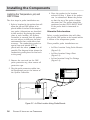
The four steps in probe installation are:
1. Select a location for the probes that will
allow the pH and ORP probes to be
placed within 6-inches of the temperature probe. (Alternatives are described
in this section). By placing the probes
close to each another, the System
Controller is assured that the probes
are not subject to different electrical
environments that could affect their
accuracy. The conductivity probe is a
special case and should NOT be
placed with the other probes—if at all
possible The diagram below shows the
conductivity probe placed in-line back
to the pump.
2. Remove the vent seal on the ORP
probe protective cap, then remove all
protective caps.
4. Place the probes in the location
selected in Step 1. None of the probes
can be submersed. Mount the probes
so that the top of the probe is above
the water line. The probes should be
positioned so that ONLY ABOUT HALF
of the probe shaft is immersed in
water.
Alternative Probe Locations
Select a probe installation that will allow
the pH and ORP probes to be located within
6 inches of the temperature probe.
Three possible probe installations are:
•
In-Filter Location Using Probe Mounts
(Figure 2.2).
•
In-Filter Location Using a Float
(Figure 2.3).
•
In-Line Location Using Tee-Fittings
(Figure 2.4).
pH
Octopus 3000
Conductivity
Probe
ORP
Temp.
3. Plug the probe connector cables into
the designated port at the bottom of
the System Controller.
Conductivity
Cell
To
Pump
Note: Conductivity Probe shown
Mounted inline.
Figure 2.2 • In-Filter Location Using Probe Mounts
2-6
CHAPTER 2: INSTALLING THE COMPONENTS
Installing the Components
In-Filter Location Using Probe Mounts—
The most common place for probe location is
in the filter. Installing probes in a filter or
sump requires that the probes be secured
using probe mounts that attach to the back
of the filter so the probes are only halfimmersed in the water, (See Figure 2.2.)
When placing your probes, be sure that
there is adequate water flow over the probe
tips at all times. The pH and ORP probes
must be placed within 6 inches of the
Temperature Probe.
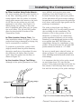
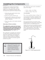
In-Filter Location Using a Float—The
float installation shown in Figure 2.3 keeps
probes from being submerged (or drying out),
and is economical to construct.
To construct a probe float, punch a hole
(slightly smaller than the probe diameter)
through a small piece of styrofoam. Be sure
the probes are no further than 6 inches
apart. Insert the probes into the float, as
shown in Figure 2.3.
OR
p
em
pH
T
In-Line Location Using a Tee-Fitting—
Although in-line probe placement is a little
more difficult and requires some extra
plumbing, it has been found to be a very
accurate and safe way to place your probes.
In-line placement will give accurate readings
because water is moving across the probe tips
at all times, and because algae growth on the
probe tips is minimized.
The probe is placed into a tee-fitting, as
shown in Figure 2.4. You will need to provide
the tee-fitting for this installation. The
diameter of the in-line portion of the tee
should be 1/2 inch (3/4” for conductivity
probe) regardless of whether you are using
laboratory or standard grade probes as they
are supplied from RK2. RK2 offers two
compression fittings for installation of the
probes. Flow rates across the pH and ORP
probes should be limited to < 10 GPM.
Be sure to install water shut-off valves, as
shown in Figure 2.6, to permit probe replacement. All fittings must be secured so there is no
water leakage.
It is important that the in-line probe extend
no more than about 50% into the flow
stream. If the probe protrudes too far into the
flow stream it will interrupt flow and interfere with the accuracy of the probe readings.
P
Probe
Shutoff
Valve
Compression
Fitting
Shutoff
Valve
Fig.2.4 • In-Line Location Using Tee Fitting
Figure 2.3 • In-Filter Location Using Float
CHAPTER 2: INSTALLING THE COMPONENTS
2-7
Installing the Components
Installing the Conductivity Probe
Installation of the conductivity probe is
similar to the installation of the pH, ORP
and temperature probes discussed previously.
The conductivity probe can be installed in
either of two ways:
•
In-line, using a tee-fitting.
•
Off-line, using a “Drip Cup.”
1. Select the proper probe location away
from the other probes.
In-Line Location
2. Remove the probe protective cap.
The in-line installation shown in Figure 2.6
is the preferred installation method because
the tee-fitting is a natural conductivity cell
and it provides the most accurate measurement environment.
3. Plug the probe connector cable into the
conductivity port at the bottom of the
System Controller.
4. Place the probe in the location selected
in Step 1.
Alternative Probe Locations
The conductivity probe must be located
away from the other three probes, and the
conductivity probe must be installed in a
controlled volume environment called a
“conductivity cell.” (See Figure 2.5)
The conductivity cell provides the conductivity probe with a controlled volume environment. The conductivity cell is required to
achieve accurate conductivity readings. It
reduces the chances that the conductivity
probe will be affected by alternate ground
(conductive) paths.
☞
Note
2-8
If the conductivity probe is not
installed in a conductivity cell
or if the probe is exposed to
electrical interference from
pumps, motors, or electrical
ballasts, unreliable readings
will result.
CHAPTER 2: INSTALLING THE COMPONENTS
The general procedure is the same as that
described above for temperature, pH and ORP
probes. However, the conductivity cell, is
utilized. Be sure that the installation provides
that about 10% of the probe protrudes into
the cell. RK2 provides a “score-mark” on all
of it’s conductivity probes that guides
installation and assures proper insertion
depth.
Probe
Conductivity
Cell
Figure 2.5 • In-Line Conductivity Cell
Installing the Components
Off-Line Location
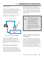
The “Drip Cup” installation is a second
option for the conductivity probe installation.
As illustrated in Figure 2.6, a portion of
water from the pump discharge line is
diverted to a small cup-type arrangement.
The water flows in and out of the cup at a
rate of about 1 cup per minute.
;;;
;;;
;
;;;
;;;
;
;;;
;;;
;;;
;;;
Installation "Vase d'Ecoulement"
Valve
Verse
l'Octopus
Pompe
Sonde de
Conductivité
Vase
which requires about 10 to 15 minutes
before accurate readings are possible. The
pH and ORP probes will take considerably
longer to stabilize. Their readings are much
more sensitive. The pH probe will stabilize
in about 24 hours while the ORP probe may
require 48 hours.
☞
Note
The System Controller has
been calibrated at the factory
to pre-set standards. Since
each probe has its own
unique measuring characteristics, it is always recommended that you perform a
manual calibration allowing
sufficient time for the probes
to stabilize in the calibration
solution.
Filtre/Bac
Figure 2.6 • “Drip Cup” Installation
In a drip cup installation, there is no
compression fitting to control insertion
depth—you must carefully position the
probe so that the end of the probe is approximately 1 inch from the bottom of the
cup.
Stabilization Period for Probes
After the probes are installed, there is a
period of time required for each probe to
stabilize in its new environment. The conductivity probe will be the first to stabilize in only
5 minutes, followed by the temperature probe
STEP 3—INSTALL DIGITAL INPUT
HARDWARE
Various system conditions, such as high or
low water levels, high or low pressures, flow
failure, or power failure can be detected and
alarmed using digital input hardware. These
devices use a switch and relay that detect and
alarm when an electrical circuit changes from
open-circuit to closed-circuit position, or
vice versa. This section provides instructions for installing a float switch (water level
CHAPTER 2: INSTALLING THE COMPONENTS
2-9
Installing the Components
detection) and a power fail detector.
RK2 offers digital input devices for water
levels, pressures, flow, and power fail
detect.
RK2 offers an optional 8-pin connector and
wire that can be used to hook up a miscellaneous digital input.
Installing a Float Switch
A float switch consists of a stationary stem
and a float that moves up and down with the
water level. When the float is in the raised
position, it is in the CLOSED position.
When the float is lowered, it is in the OPEN
position.
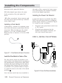
the tank or filter, connect the 8-pin connector to the bottom of the System Controller
(in the 8-pin digital input port).
Installing the Power Fail Detector
A power fail detector is available from RK2.
This 9-volt wall mount device is configured
with an 8-pin connector, as shown in Figure
2.8. Install the unit as follows:
1.
Plug the 9-volt power detect switch into
a 110-V outlet.
2.
Plug the 8-pin connector into the
bottom of the System Controller. (At
the 8-pin General Input port.)
STEP 4—INSTALL THE OPTIONAL
9-Volt
Power Fail
Detector
Octopus 3000
Modem
X-10
Control
Module
X-10
Figure 2.7 • Float Switch with 8-pin Connector
Power
Supply
Install the Float Switch in Tank or Filter
The float switch should be installed in the
tank or filter at the desired level, according to
the manufacturer’s instructions. (Many float
switches will require drilling into the tank at
the desired float location.) Be sure the float
is installed in the position shown in Figure
2.7 (with the arrow on the side of the switch
pointing up).
Once the float switch has been installed in
2-10
CHAPTER 2: INSTALLING THE COMPONENTS
Surge
Suppressor
Probe Cables
Octopus Power
Transformer
Plugged Into
Surge Suppressor
Figure 2.8 Power Fail Detect Installation
Installing the Components
X-10 POWER LINE INTERFACE
shown in Figure 2.9.
To install the X-10 Power Line Interface,
simply plug it into a GFCI electrical outlet.
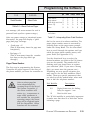
Then use the 4-wire interconnect cable
provided with your unit to connect the X-10
Power Line Interface (RJ-11 port at the
bottom) to the System Controller. For
proper initialization of these components,
remember to connect your X-10 Power Line
Interface and Control modules before powering up your System Controller unit.
To install the Control module, simply plug
the module into a GFCI-protected electrical
outlet. Then plug the device to be controlled
(i.e., pump, heater, chiller) into the bottom of
the Control module.
STEP 5—INSTALL AND ADDRESS
OPTIONAL CONTROL MODULE(S)
The Control modules can be located wherever
electrical power is available. It is essential,
however, that the System Controller, the X10 Power Line Interface, and all Control
modules be located on circuits on the same
phase in the electrical sub-panel and have
the distance of the A/C wiring between the
X-10 Power Line Interface and any Control
Module not exceed 50 feet. Otherwise, these
devices may not communicate properly.
One Control module will be needed for each
peripheral device you want to control, as
Be sure you do not exceed the power specifications of the Control module. The Control
modules operate on power lines up to 110
volts and can be used with devices up to 15
amps. Control modules which operate with
higher voltage and amperage or with different
international plug configurations, are available from your dealer.
The System Controller identifies each
Control module by its own code, which is
called an address. A control address must
be set for each Control module.
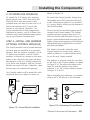
The address is selected using the two dials
on the face of the Control module, as shown
in Figure 2.10. The alpha dial allows selections A-P and the numeric dial allows
selection 1-16. The Control address shown
in Figure 2.10 is A-3.
Before assigning any addresses, you should
make a list of all devices to be controlled
GFCI
15
15
AQUADYNE
TM
1
3
5
11
O
9
UNIT
A
C
E
K
I
ID
G
5
13
7
M
SATELLITE
1
3
13
Heater
11
15
TM
AQUADYNE
TM
1
3
Control Module
5
13
11
O
9
UNIT
A
O
C
A
Adresse: A-3
C
E
K
TM
7
7
M
Control Module
9
UNIT
I
ID
G
M
E
K
I
ID
G
Figure 2.10 • Addressing a Control Module
Figure 2.9 • Control Module Installation
CHAPTER 2: INSTALLING THE COMPONENTS
2-11
Installing the Components
and their proposed Control addresses. It is
recommended that you use the addresses
supplied by RK2. They will minimize the risk
of control problems caused by interference.
The default addresses are shown in Table 2.2.
The System Controller comes pre-programmed with these addresses already
installed in the controller.
☞
Note
Do not plug Control Modules or
the X-10 Power Line Interface
into power strips equipped with
surge suppression. Surge
suppression will filter out the
System Controller X-10 control
command signals.
Default Control Addresses
H-1
C-1
O-1
D-1
D-2
F-1
A-1
C-2
C-3
Heater
Chiller
Ozonizer
Buffer System (pH)
CO2 Doser
Main Pump (System Hold)
Alarm Module
Low Cond. Control
High cond. Control
P-1
P-2
P-3
P-4
WaveMaker Pump 1A
WaveMaker Pump 1B
WaveMaker Pump 2A
WaveMaker Pump 2B
L-1
L-2
L-3
L-4
L-5
L-6
•
•
•
L-16
Timer
Timer
Timer
Timer
Timer
Timer
1
2
3
4
5
6
Timer 16
Table 2.2 • Default Control Module
Addresses
2-12
CHAPTER 2: INSTALLING THE COMPONENTS
The X-10 Power Line Interface
and all Control modules must be
installed on circuits of the SAME
PHASE. If the X-10 Power Line
Interface and the Control
modules are not on the same
phase, they will not be able to
communicate with each other,
except by means of a X-10
Signal bridge.
!
CAUTION
A sticker on each satellite
module indicates the maximum
load-rating of the device.
DO NOT OVERLOAD. Equipment such as compressors and
pump motors can exceed the
load rating of a Control module.
Verify with the manufacturer of
your peripheral device that the
surge current at startup does
not exceed the load rating of the
satellite module. Damage to the
satellite unit could result!
In addition, be sure you are
using the correct plug configuration.
Installing the Components
STEP 6—INSTALL THE
COMMUNICATIONS EQUIPMENT
There are two optional communication
features available for the System Controller
system:
•
Alarm Paging
•
AquaWeb for Windows
The alarm paging feature allows your pager
to receive an alarm page when a water quality
parameter goes outside the acceptable range
or when a digital input switch signals an
alarm condition. The pager message indicates
which System Controller unit (via the last 3
digits of the unit serial number) is affected
(in the event of multiple units), which
parameter is involved, and whether the
alarm represents a high or low condition.
(Refer to Chapter 3, Step 23 for a discussion
of pager message information.)
As shown in Table 2.3, in order to have the
alarm paging feature, you must install a
modem to your system.
Communication Feature
AquaWeb for Windows 9x/NT/2000
provides remote access to the System
Controller internal data-log and permits
network communication between a PC and
the System Controller. Depending on the
software version of AquaWeb, some of the
features include remote communications,
trend analysis and networking with extensive graphing, statistical and data export
capabilities.
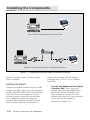
As indicated in Table 2.3, there are two ways
to access AquaWeb:
•
Via modem
•
Via direct cable connection
For a single PC to a single System Controller, a direct cable connection can be used
(refer to Figure 2.11). Note that if a direct
cable connection is used, alarm paging will
not be available. (Both the direct cable
connection and the modem connection
require a serial port connection. And PCs
typically have only one serial port available.)
For remote access to the System Controller
data-log or for networking two or more
Connection Options Available
Direct Cable
Modem
Connection
Alarm Paging Only
✔
N/A
AquaWeb Only
✔
✔
✔
Both Alarm Paging & AquaWeb
N/A
Table 2.3 • Communication Options
CHAPTER 2: INSTALLING THE COMPONENTS
2-13
Installing the Components
Direct Cable Connection for Local Use Only
Modem Connection for Remote or Networking Access
Figure 2.11 • AquaWeb using Direct Cable or Modem Connection
System Controller units, a modem connection is required.
Installing the Modem
Using the AquaWeb software requires a RK2
modem. Non RK2 modems are not supported
by RK2. The RK2 modem and 10-foot modem
cable (RS-232) are preconfigured to work
with the System Controller unit and there
are no adapters needed. If you did not
purchase this hardware from RK2 you will
need to follow additional instructions to
2-14
CHAPTER 2: INSTALLING THE COMPONENTS
connect your modem with the System
Controller unit. (A Tech- Tip is available
from RK2.)
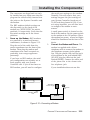
1.
Connect the Modem and the System
Controller Unit—First, plug your
modem cable into the modem/serial
port of the System Controller unit.
Then connect the other end of the
modem cable into the 25-pin connector
on the back of the modem, as
illustrated in Figure 2.12.
Installing the Components
the serial port settings on the modem.
Normally, this will require that your
settings support the port settings of
your System Controller (baud rate of
19,200 and data format of 81N). If you
are using AquaWeb, you will also need
to configure the modem to autoanswer.
The connectors are keyed and can only
be installed one way. Make sure that the
plugs on the cable are fully inserted into
the jacks on the System Controller and
the modem.
The RK2 modems default settings on
the dip-switch (at the back of the
modem) are “DUDUUUDD” for switch
positions 1-8 respectively. Verify that the
dip-switch settings are in the correct
positions.
2.
Power up the Modem—RK2 modems
are powered by a small wall-mount
transformer, as shown in Figure 2.12.
Plug the end of the cable from the
power transformer into the front of the
modem. Then plug the modem wall
transformer into a wall receptacle or,
preferably, into a surge suppressor
powerstrip.
If you have an RK2 modem, the serial
port configurations are already set to
work properly with your System
Controller unit. If you do not have an
RK2 modem, you will need to configure
A small power switch is located on the
back of the modem. Set the power switch
on the modem to the ON position. When
the modem has power, several red lights
should be illuminated on the front of the
device.
3.
Connect the Modem and Phone—The
modem is supplied with a 6-foot
telephone cable to connect the modem to
the telephone company (telco) phone
line. Plug the phone cable into the back
of the modem in the jack labeled LINE.
(DO NOT plug the cable into the jack
labeled PHONE.) Connect the other end
of the phone line to the closest telco
live telephone jack.
If your installation does not use this
Wall Mount
Power Supply
☎
Telephone
Line
Modem/ Serial
Port
Modem
Figure 2.12 • Connecting a Modem
CHAPTER 2: INSTALLING THE COMPONENTS
2-15
Installing the Components
!
CAUTION
There could be problems in
modem operation and pager
functionality if the telephone
line is shared. For proper
operation, the modem will
required a dedicated telephone line.
!
CAUTION
The cable utilized for Direct
Cable connection is a nonstandard cable. It can be
ordered from your dealer or
from RK2.
type of phone connection, adapters are
available through your local computer
hardware store. With the cable
connected to the phone line, you are
now ready to program the H2O/S
software for modem use. (Refer to
Chapter 3, Step 23.)
Your System Controller with its H2O/S
system software can be configured to connect
directly to a PC by using RK2’s direct cable
connection. Once connected, the System
Controller can communicate with AquaWeb
for Windows, RK2’s remote access applica-
Installing the Direct Cable Connection
General Input
(8-pin mini-DIN)
Use of any cable other than
that supplied by RK2 may
result in an incomplete
connection or, in extreme
cases, damage to the
System Controller or
computer.
ORP Probe (BNC)
X-10 Control
Module (Telco)
Temp.Probe
(Telco)
9V Battery B/U
(Stereo jack)
Power
(9V-AC Power Jack)
Conductivity
(4-pin mini-DIN)
pH Probe
(BNC)
Figure 2.13 • Bottom View of the System Controller
2-16
CHAPTER 2: INSTALLING THE COMPONENTS
Modem/Serial Port
(8-pin mini-DIN)
Installing the Components
tion, and the H2O/S Flash downloader
application.
To hook up directly to the PC, one end of the
direct cable connects to the serial port on
the System Controller unit and the other
end connects to your PC com port. RK2
provides a optional 25 and 50-foot extension
cables for longer runs.
Along with the cabling issue the System
Controller allows you to control a number of
different serial data options such as baud
rate, parity, and software flow control.
STEP 7—POWER UP THE SYSTEM
If your system includes a modem, X-10
Power Line Interface or Control modules, be
sure that these components are plugged in
BEFORE powering up the System Controller.
Plug the end of the cable from the power
transformer into the power jack located on
the bottom left of the System Controller
(See Figure 2.13). Be sure to use the protective power cord drip loop to prevent water
from running down the cord into the System
Controller. The cord should extend below
the outlet so that any runoff will not enter
the electrical outlet.
When the controller is first plugged in, it
goes through a diagnostic self check. The
LCD screen will show a series of messages
indicating that a self diagnosis is in
progress, as shown in Figure 2.14.
Diagnostics
de démarrage
OCTOPUS 3000
Aquadyne Inc.
Ver. 2.0
Ser #97-1234567
CONTROLLER
Version du Logiciel
et numéro de serie
Copyright (C)
1992-1997
When powering up the System Controller for
the first time, make note of your system
serial number and H2O/S software version.
This information is required should you find
Auto Test
08/15/97 11:45AM
Auto Test ok
Initialisation
sorties num.
Current Readings Rotate thru
Top Line of the Display
Installatin/Detection
de l'Interface et de Modules
ORP= 350mV
CD 45.4mS
T= 78.2F
pH= 8.20
All Systems Normal <---
Initialisation
Terminée
Initialisation
Modem: +++
pH = 7.8
Changes In System status
Rotate thru Bottom Line
of the Display
Initialisation du
Modem
Initialisation
Modem: Envoie
HEATER SYSTEM IS ACTIVE
ORP SYSTEM IS ACTIVE
pH LOW ALARM
Figure 2.15 • Current Status Window
Figure 2.14 • Startup Diagnostics
CHAPTER 2: INSTALLING THE COMPONENTS
2-17
Installing the Components
it necessary to obtain technical support.
When the current status screen begins to
display you will notice that the top line of
the display will show the current probe
readings. The second line will show system
activity such as systems being activated,
and alarms occurring. When the Current
Status Screen is shown, Figure 2.15, you are
ready for programming the System Controller.
Transformateur
Branché dans
Suppresseur
de Tension
9V Batterie
Pack
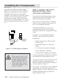
Figure 2.16 • Battery Backup Installation
!
CAUTION
2-18
To install the 9-Volt Backup Battery Pack,
simply plug in the battery backup to the
bottom of the System Controller.
Note: You need to install two 9V Alkaline
batteries into the battery backup pack. Do
not use rechargeable batteries.
CONGRATULATIONS—You have now
completed the first half of the System
Controller installation—components installation
Octopus
Cables de Sondes
STEP 8—INSTALL THE 9-VOLT
BACKUP BATTERY PACK
(OPTIONAL COMPONENT)
Please note that the 9-Volt
Backup Battery incorporates
special hardware designed
by RK2 specifically for the
System Controller. The use
of any other voltage source
could cause damage to your
System Controller.
CHAPTER 2: INSTALLING THE COMPONENTS
In Steps 1-8, you mounted the System
Controller and installed the following
components:
•
Probes (Temperature, ORP, pH and
Conductivity).
•
Digital Input Switch or Device (optional).
•
X-10 Power Line Interface (Optional).
•
Control Module(s) (Optional).
•
Communications Equipment (Optional).
You then powered up the System Controller
and installed the Backup Battery Pack.
You are now ready for the second half of the
installation process: programming the
System Controller H2O/S software (Steps 925), presented in Chapter 3.
Don’t worry, you don’t have to be a computer
programmer to successfully program the
System Controller. We not only give you the
roadmap (the Menu Map), we guide you
down the road as well.
Chapter
3
Programming
the
Software
Programming the Software
PROGRAMMING THE SOFTWARE
Your RK2 System Controller includes the
latest version of the H2O/S software which
was pre-loaded into FLASH memory at the
factory prior to shipment. The FLASH
memory design of the System Controller
allows future software upgrades to be
installed by the user as they are made
available by RK2.
For additional information pertaining to the
latest software release, visit our WEB page:
http://www.RK2.com
For this part of the installation process, we
recommend that you have your laminated
Quick Reference Menu Map card at hand to
follow along with the description. This will
familiarize you with the Quick Reference card
as well as introduce you to the use of the
System Controller software menus. Detailed
Menu Maps are given in Appendix A.
Before you begin entering setpoint data, we
thought it would be beneficial to review the
general structure of the System Controller
menus.
Overview of the System Controller
Menus
All software menus and data entries are
viewed through the LCD Screen Window on
the face of the System Controller (Figure
3.1). The screen typically shown in the
window is the Current Status Screen. This
screen gives current probe readings for each
of the four parameters: conductivity, temperature, pH and ORP
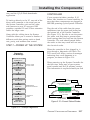
Figure 3.1 • System Controller
The Current Status Screen is only one of
several screens that comprise the Top Level
Display. Side One of the Quick Reference
Menu Map shows all available Top Level
Displays.
To scroll through the Top Level Display,
simply push the right or left arrow on the
keypad. The screens will be shown in the order
indicated on the Menu Map. You can cycle
through the screens as many times as you
desire in either direction.
The Current Status Screen provides both
current parameter information (i.e. pH, ORP,
Conductivity, and Temperature) on the top
line and system status on the lower one. As
systems are activated or alarms are triggered
the status line provides up to date status on
the system being managed. As events occur
they are entered
08/15/97 11:45AM
pH = 7.8
Current Readings Rotate thru
Top Line of the Display
ORP= 350mV
CD 45.4mS
T= 78.2F
pH= 8.20
All Systems Normal <--Changes In System status
Rotate thru Bottom Line
of the Display
HEATER SYSTEM IS ACTIVE
ORP SYSTEM IS ACTIVE
Top Level Display
pH LOW ALARM
Figure 3.2 • Current Status Display
3-2
CHAPTER 3: PROGRAMMING THE SOFTWARE
Programming the Software
into the lower display. Up to 16 events are
saved and displayed in sequence. Figure 3.2
shows the current status window.
Main Menu
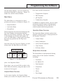
The Main Menu is comprised of three
primary sub-menus, as shown in Figure 3.3
•
Setpoints Menu
•
Operation Menu
•
Setup Menu
These menus are the first level down from the
Top Level Display and comprise the Main
Menu for the System Controller. This menu
is the doorway to all other sub-menus. To
enter the Main Menu, simply push the Enter
key from any position on the Top Level
Display.
Note that from the Top Level Display you will
always enter the Main Menu at the same
TOP LEVEL DISPLAY
Exit
Main
Menu
Setpoint
Menu
Operation
Menu
four water quality parameters:
•
Temperature Setpoint
•
ORP Setpoint
•
pH Setpoint
•
Conductivity Setpoint
In addition to setpoint values, you can input
parameter setpoint ranges, and parameter
control information for use with the X-10
control system and alarm generation.
Operation Menu Overview
The Operation Menu includes options that
might be required in day-to-day operation of
the System Controller:
•
Control Menu
•
Probe Calibration
•
Lock/Unlock Password
•
Clean Probes
•
IR Printer Menu
Setup Menu Overview
Setup
Menu
Figure 3.3 • The Main Menu
place: the Setpoints Menu.
From there, you can scroll left or right in the
Main Menu as desired, using the right or left
arrows on the keypad.
Setpoint Menu Overview
The Setup Menu is used primarily during
initial setup of the System Controller,
including:
•
Test Menu
•
Set Module ID
•
New Password
•
Temp Scale
•
Timers
•
Alarm
•
Data Logger
As the name implies, the Setpoint Menu
allows you to enter the setpoint values for the
CHAPTER 3: PROGRAMMING THE SOFTWARE
3-3
Programming the Software
•
Wave-Maker
•
Filter
•
Pager (optional)
•
Conductivity
•
Digital Input
arrow key until you reach pH
Setpoint. Then press Enter.
•
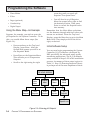
Using the Menu Map—An Example
Suppose, for example, you wish to enter the
pH setpoint for the System Controller . To do
this, you would follow these steps (See
Figure 3.4):
•
From anywhere on the Top Level
Display, press Enter . After the
System hold prompt you will be at
the Setpoints Menu.
•
Press Enter at the Setpoints Menu.
This will take you to Temperature
Setpoint.
•
Scroll to the right using the right
You will then be at pH Setpoint.
Move the arrows left or right to find
the desired pH value. Then press
Enter to record the Setpoint value
into memory.
Remember that the Main Menu selections
are the doorway through which all other submenus are accessed. From the Top Level
Display, press the Enter key to get to the Main
Menu level. Then simply scroll to the left or
right, as desired.
Initial Software Setup
You can now begin programming the System
Controller H2O/S software—developed by
RK2 specifically for advanced water quality
monitoring applications. The H2O/S software
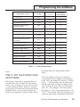
setup consists of Steps 9-23 in the installation
process. A summary of these steps is given in
Table 3.1. Step 15 (Entering Setpoint Values)
is perhaps one of the most important of these
TOP LEVEL DISPLAY
Cond.
Setpoint
Exit
Main
Menu
Setpoint
Menu
Operation
Menu
Setup
Menu
Exit
Setpoints
Temp
Setpoint
ORP
Setpoint
pH
Setpoint
pH Setpoint
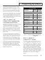
Setpoint=x.xx
3-4
Figure 3.4 • Entering pH Setpoint
CHAPTER 3: PROGRAMMING THE SOFTWARE
Programming the Software
On M e nu
Monitoring
System
M onitoring &
Control Sys te m
9. Set System Clock
Setup
X
X
10. Enter Password
Setup
Optional
Optional
11. Set Noise Filter Control
Setup
X
X
12. Select the Conductivity Temp.
Compensation Settings
Setup
X
X
Initial Software Se tup
13. Select Conductivity Range
Setup
X
X
14. Select Temperature Scale
Setup
X
X
Setpoint
X
X
16. Enter the Alarm Range Values &
Hold- Off Timer
Setup
X
X
17. Setup Digital Input Alarm
Setup
X
X
18. Setup Lighting System
Setup
NA
X
19. Setup Wave Maker System
Setup
NA
X
20. Setup System Hold
Setup
NA
X
21. Assign Control ID’s on Software
Setup
NA
X
22. Setup the Pager Alarm
Setup
X
X
Operations
NA
X
Setup
NA
X
15. Enter Setpoint & Range Values
(Cond., Temp., pH, ORP)
23. Enable Octopus System Control
24. Test the System Configuration
Table 3.1 • Initial Software Setup
steps.
STEP 9—SET THE SYSTEM CLOCK
(SETUP MENU)
The System Controller is equipped with an
internal clock that includes its own battery
source. So, you won’t need to set the clock as
a result of power failure. However, because
each clock is set from the factory with Pacific
Standard Time, you may need to adjust the
clock to your time zone. Control of the clock is
accessed under the Setup Menu under
Timer.
Your first option in setup is to load the
current date. Data is loaded in the following
order: First, the month (01=January, 02=February. . ., 12=December), then the day of the
month, and finally the last two digits of the
year. To enter the year 1997, you would only
enter "97." For example, if the current date
were May 16, 1997, then you would enter "05/
16/97." The controller will then prompt you to
verify the date before continuing to enter the
CHAPTER 3: PROGRAMMING THE SOFTWARE
3-5
Programming the Software
time. If you answer NO to the question
"Correct?," then you have an opportunity to
re-enter the date.
Next, enter the time in a 12-hour format.
After the time is entered you are again given
the opportunity to verify that what you
entered is correct. If you answer NO, then you
will be given another opportunity to enter the
time.
STEP 10—ENTER THE
PROTECTIVE PASSWORD
The use of a password will protect your
controller from unauthorized use. Anyone
attempting to use the controller will not be
able to enter the Main Menu without entering
the correct password. Your password may
consist of up to five characters, letters and/or
numbers. You may choose not to utilize the
password protection; if so, do not enter any
password and move to the next setup procedure.
Many people find password numbers easier to
remember; you may want to choose a number
you already use somewhere else, such as an
☞
Note
3-6
Entering “AQDYN” at the new
password prompt will
display the system serial
number and the version of
H2O/S software installed in
the System Controller. This
information will be required
should you need to contact
technical support for any
reason.
CHAPTER 3: PROGRAMMING THE SOFTWARE
address. To enter your password, go to the
“New Password” selection in the Setup Menu.
When you press Enter, you will be prompted
to enter your password of up to five characters. To do so, push the arrow until the first
character you desire appears, then push
enter. Follow this process for the remaining
characters of your password. If your password has less than five characters, push enter
a second time to signal that your password is
complete. You will be prompted to enter the
same password a second time to ensure that
the password has been entered correctly.
When your password has been entered and
verified the LCD Screen returns to the "Exit
Password" Screen.
In order to activate your password selection go
to the Operations Menu, press Enter, then
scroll using the arrows to the "Lock-Unlock"
menu. Push Enter and the display will show
"Lock Now." Push Enter and you have activated the password.
STEP 11—SET THE NOISE FILTER
CONTROL
The System Controller comes with a software
noise filter which minimizes the effects of
electrical noise on probe measurements. The
filter may be set to one of four states: Off, Low,
Medium, or High. Unless your System
Controller is having problems recording data
into the data-log, we recommend an initial
setting of Off. If your aquatic environment is
stable, but your HP hand-held printer output
is showing unusual “high-low” readings,
then some adjustment to the filter setting is
Programming the Software
warranted. It is always advisable to first
identify and eliminate the source of the
interference —before attempting to use the
filter to achieve the same goal. The filter
menu is accessed under the Setup Menu.
Note that the noise filter does not alleviate
the X-10 control problems associated with
electrical noise. Contact your nearest X-10
control module dealer who can help troubleshoot installation problems.
STEP 12—SELECT THE
CONDUCTIVITY TEMPERATURE
COMPENSATION SETTINGS
Temperature will affect conductivity readings.
Therefore a temperature compensation
adjustment is provided. This adjustment
allows you to artificially adjust the conductance reading in percent per degree Celsius
from 0 to 5% per °C. As a general rule, an
adjustment of 2-3% is common for the water
environment.
To reach the temperature compensation
menu (“Temp Comp Menu”), press Enter on
the Setup Menu, then press the arrow keys
until you scroll to the Conductivity menu
(Cond. Menu). When you press Enter again,
you will be at the Temp Comp Adjust Menu.
NOTE: You can test the required percent
adjustment setting by using water temperatures of known conductivity value and
observing the conductivity readings. The
readings should stay constant as the water
changes temperature.
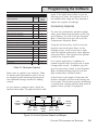
ON THE SETUP MENU
Value Required
Monitoring Monitoring &
System Control System
Conductivity
Temperature Compensation
X
X
Conductivity Range
X
X
Conductivity Alarm
X
X
Temperature Scale
X
X
Temperature Alarm
X
X
Temperature
pH
Dosing Mode
pH Alarm
X
X
X
X
X
ORP
ORP Alarm
Table 3.2 Parameter Settings Included in the
Setup Menu
STEP 13—SELECT A
CONDUCTIVITY RANGE
The conductivity range menu allows you to
set the appropriate conductivity scale. This
is important since the conductivity range of
water varies greatly depending on the application. Saltwater, for example, ranges from
about 45,000 to 55,000 µS (45mS - 55mS),
whereas freshwater conductivity is typically
between 800 and 1,500 µS, depending on the
water source. Hydroponic and other applications can vary across a broad range as well,
depending on the crop and the stage of
growth.
CHAPTER 3: PROGRAMMING THE SOFTWARE
3-7
Programming the Software
You will need to select the conductivity scale
that is appropriate for your system. The
conductivity scale choices are 0-1000 µS (low
range), or 0-100 mS (high range). The first
scale is a much more sensitive scale since it
reflects changes in conductivity of only one
microSiemen (1 µS). The second scale is less
sensitive and reflects conductivity changes in
increments of 100 µS.
From the Setup Menu, press Enter to reach
the submenus. Use the directional keys to
scroll through the Sub-menu options. Once at
the conductivity range, press Enter.
STEP 14—SELECT A
TEMPERATURE SCALE
The temperature scale menu allows you to
select the scale you wish to use for temperature measurement—Celsius or Fahrenheit.
The System Controller controller is set to
Fahrenheit at the factory.
Changing the temperature scale automatically recomputes your setpoints. For example, if your setpoints were entered in
Fahrenheit and you change the temperature
scale to Celsius, all of your setpoints will be
automatically converted to their Celsius
equivalents.
The Temperature Scale Menu is accessed by
pressing Enter at the Setup Menu. Use the
directional keys to scroll through the menu
options until the temp scale menu is reached.
Press Enter to access the item, and use the
directional keys to choose a temp scale.
3-8
CHAPTER 3: PROGRAMMING THE SOFTWARE
STEP 15—ENTER SETPOINT AND
RANGE VALUES
Various setpoints and ranges must be
established for each of the four monitoring
parameters: conductivity, temperature, pH
and ORP
There are three values that must be entered:
•
The optimal setpoint value (in Step 15).
•
The control range (in Step 15.
•
The alarm range (in Step 16).
When these three values are entered, the
system will operate as illustrated in Figure
3.5. As long as the water quality parameters
remain within the acceptable operating range,
no control or alarm will be activated. If,
however, the parameter rises above or falls
below the acceptable operating range, the
System Controller will activate the appropriate control device. The control device remains in operation until the parameter
returns to the Setpoint value. (For ORP, the
control device remains in operation until the
ORP value returns to the HIGH control
point.)
Entering Data on the Setpoints Menu
Generally speaking, you enter or change any
setpoint by first pressing Enter from any
position on the Top Level Display. This will
bring you to the Setpoints Menu. Press Enter
and you will be at the “Temp Setpoint” menu.
Scroll left or right using the arrows until you
arrive at the desired parameter. Press Enter.
When the current setpoint is displayed, push
the right arrow to increase the value or the
left arrow to decrease the value. Once the
setpoint value you want is displayed, push
Programming the Software
ON SETPOINT MENU
Monitoring Monitoring &
Control
System
System
Value Required
Conductivity
Conductivity Setpoint
X
X
Conductivity Range
X
X
Low Conductivity Dose Time
X
Low Conductivity Dwell Time
X
High Conductivity Dose Time
X
High Conductivity Dwell Time
X
Temperature
Temperature Setpoint
X
X
Temperatrue Range
X
X
pH Setpoint
X
X
pH Range
X
X
pH
X
Dose Time
Dwell Time
X
CO2 Doser Time
X
CO2 Dwell Time
X
OR P
ORP Setpoint
X
X
Table 3.3 • Parameter Setpoints
Enter once to register your selection. Table
33 shows which parameters need to be set
for monitoring and alarming functions and
the additional settings needed for adding
control.
As you choose a setpoint value, check the
System Status light. The light should be solid
Lower
Parameter
Values
Low
Alarm
ON
Low
Control
ON
Low
Low
Alarm
Control
Setpoint Setpoint
Acceptable
Operating
Range
Optimal
Setpoint
Value
green. If the light turns yellow as you are
selecting your value, the setpoint is out of
the normal value range for that parameter.
Adjust the setpoint accordingly.
Conductivity Setpoints
To enter the conductivity optimal setpoint
value, press Enter from any place on the Top
Level Display. You will be at the Setpoints
Menu. Press Enter and you will be at the
Temperature Setpoints Menu.
Using the left arrow key, scroll to the conductivity menu and press Enter. At the
flashing screen, scroll to the left or right
until the desired conductivity value appears
and press Enter. This registers the optimal
conductivity setpoint value.
In a control application, in addition to
optimal setpoint value you will need to enter
a range value as well, in addition you will
need to enter other values in the Setpoints
Menu including dosing times for low and
high conductivity, and dwell times.
A dwell time is the length of time that the
System Controller will wait until dosing can
occur again. This feature prevents overdosing
a system with a dosing solution and protects
against “short cycling” of equipment.
High
Control
ON
High
Alarm
ON
High
High
Control
Alarm
Setpoint Setpoint
Higher
Parameter
Values
Figure 3.5 • Control Systems Setpoint and Ranges
CHAPTER 3: PROGRAMMING THE SOFTWARE
3-9
Programming the Software
Conductivity Example
Suppose that you desire an optimal setpoint
value of 45 mS, an operating range of ±5 mS
and an alarm range of ±3mS. Figure 3.5
illustrates the relationship between the
optimal setpoint value, and the control
range.
For these systems, if the conductivity value
☞
Note
Note that the chiller system has
a protective feature that prevents the chiller from turning
on/off more often than every 10
minutes.
remains within the target operating range,
the parameter status light will not be
illuminated. If the conductivity value enters
the control range, the parameter status light
will turn either red if the low conductivity
dosing system is enabled, or green if the
high conductivity dosing system is active. If
the parameter status light is flashing red,
the low conductivity dosing system is in a
dwell state. A high conductivity dosing
system dwell state is indicated by a flashing
green parameter status light (See Figure
1.2).
Temperature Setpoints
The temperature setpoint defines the
optimum water temperature. In a control
application you will also need to enter the
control range on the Setpoint Menu.
3-10
CHAPTER 3: PROGRAMMING THE SOFTWARE
To enter the temperature setpoint, go to the
Setpoints Menu. Press Enter and you will be
at the Temperature Setpoint Menu.
When you press Enter again the current
temperature setpoint will begin flashing on
the LCD display window. Pushing the right
arrow will increase the setpoint value and
pushing the left arrow will decrease the
setpoint value. When the desired value is
displayed, push the Enter key to select it.
If the system is configured for monitoring
and control, you will need to enter values for
the temperature range in addition to the
temperature setpoint. This determines the
control range for heating and chilling devices.
Since most heaters and chillers have their
own thermostat, these thermostats can be
used as a backup temperature control
system. The heater thermostat should be set
several degrees above your desired temperature and the chiller several degrees below. If
your desired temperature is 78°F then set
your heater thermostat at 81°F and your
chiller thermostat at 75°F.
Temperature Example
☞
Note
Configuration data such as
setpoint values, are stored in
permanent (nonvolatile)
memory. Should primary or
backup power to the System
Controller be lost, the setpoint values will be restored to
their previous values when
power is restored to the
System Controller.
Programming the Software
Suppose you have a setpoint value is 78.2
°F, your target operating range is ±0.1 °F, and
the alarm range is 0.1 °F. (Figure 3.5 illustrates the relationship between the setpoint
value, and the control and alarm ranges.)
If the temperature stays within the target
operating range (78.1–78.3 °F), the parameter
status light will remain off.
If, however, the temperature enters the
control range (between 78.1°F on the low
side and 78.3°F on the high side), the
parameter status light will either turn green
if the chilling system is active, or red if the
heating system is active.
At the beginning of the control range, the
System Controller will turn on the chiller or
heater, as needed. These peripheral devices
will remain activated to drive the temperature value back to the optimal setpoint, and
once achieved, the peripheral device will be
turned off.
pH Setpoints
The pH setpoint defines the optimum pH
level that you wish the System Controller to
maintain in the aquatic environment. To
enter a pH optimal setpoint value, go to the
Setpoint Menu. Press Enter and use the
right arrow to reach the pH Setpoints Menu.
When you press Enter, the current pH
☞
Note
Note that if the dose time is set
to 0, the dwell time entered will
be ignored by the System
Controller and the unit will
continue to dose buffer until
the pH returns to the Optimal
Setpoint Value.
setpoint will flash on the LCD display. Push
the right arrow to increase the setpoint
value or the left arrow to decrease the
setpoint value. When the desired value is
displayed, push Enter to register your
selection. Other setpoint values are entered
similarly. For controlling pH additional values
must be entered on the Setpoints Menu,
including the dose and dwell values.
The System Controller can control the pH
system by dosing a buffer solution or injecting
CO2 gas or do both.
The pH control range is selectable from ±0.05
pH units to ±1.00 pH units, and determines
the ON points for the pH and CO2 dosing
systems.
The Current Dose in minutes (time per dose
of buffer solution) will flash on the screen.
This is the number of minutes that the
System Controller will dose buffer to bring
the pH level back up into the Setpoint . The
acceptable values for buffer solution dosing
are from 1 to 99 minutes.
Dose Time
0 Sec.
1-99 Sec.
CO2 System
Pressurized Systems
Non Pressurized Systems
Table 3.4 • CO2 Dose Time
Dose times will range from 0-99 minutes.
You are also required to enter a dwell time—
The Dwell Time is the length of time that the
System Controller will wait until dosing can
occur again. This feature prevents overdosing
a system with buffer.
CHAPTER 3: PROGRAMMING THE SOFTWARE
3-11
Programming the Software
The next option is the setting of the CO2
Dosing, in seconds. This controls how long
the CO2 gas valve will remain open. The
possible values range from 0 to 99 seconds.
For example, if you enter 10 seconds, when
the upper end of the target operating range
for pH is reached, the System Controller will
turn on the CO2 gas for 10 seconds to
reduce the pH to a lower value. A CO2 Dwell
Time will force the System Controller to wait
to allow the gas to be absorbed into the
water. This will prevent the pH value from
dropping to fast.
If you enter a value of 0 seconds, then the
System Controller will turn the gas valve on
when the pH level reaches the high end of
the target operating range and will keep the
valve open until the pH drops below the
optimal pH level. The 0 seconds option is for
systems with pressurized CO2 injection.
The last pH control selection is the CO2
dwell time. This is the time that the System
Controller waits before allowing another
CO2 gas injection to occur. This time is
selectable from 1-255 minutes.
If the System Controller senses that the pH
is outside of the target operating range, it
will turn on the pH doser or CO2 injector
until the pH returns to the optimal setpoint
range (See Figure 3.5).
An red parameter status light indicates the
CO2 dosing system is active, while an green
status light indicates the buffer dosing
system is active
A CO2 dwell time is indicated by a flashing
red status light while a flashing green light
indicates a buffer dosing system dwell time.
3-12
CHAPTER 3: PROGRAMMING THE SOFTWARE
ORP Setpoints
The ORP setpoint defines the acceptable
level of oxidation reduction potential in the
aquatic environment. The ORP level is an
indicator of ozone. Acceptable levels are
between 200 and 450 mV. The ORP setpoint
can be maintained through the use of an
ozonizer in Monitoring and Control System.
However, unlike the proceeding parameters,
the ORP setpoint has a FIXED range of ±5
mV.
Verify All Setpoint Settings
You can easily view the parameter setpoints.
From the Top Level Display, simply push
either the right or left arrow keys to scroll
through the screens. Each successive push
of an arrow will display another setpoint
until it returns to the current status screen.
Push Enter at any time to enter the other
menus.
STEP 16—ENTERING ALARM
RANGE
General Alarm System
The alarm is located in the Setup Menu
under Alarms. All alarm ranges are entered
in this menu. The alarm range can only be
☞
Note
The high or low alarm trigger
points are computed by adding
the control value and the alarm
value to the setpoint value.
Programming the Software
entered if the alarm system itself is also
enabled first. In addition to an alarm range
for each system there is a common alarm
hold-off time which can be entered. This will
prevent any system for generating an alarm
until the hold off time has expired. Table 3.5
lists all system parameters that are located
in the Setup menu relating to alarming or
system configuration.
When a alarm occurs the status line on the
LCD screen will show which system(s) had the
alarm and whether the alarm was a high or
low alarm condition. When the hold-off time
has expired the controller will generate an
audible alarm and initiate a alarm page if the
pager system is enabled on the controller. The
alarm condition is reset by pressing the Enter
button on the front of the controller. Pressing the Enter key during an alarm will stop
the audible alarm and cancel any pending
pages but the alarm status messages will
NOT be cleared until the alarm condition is
no longer sensed by the controller.
Alarm will be triggered when the value
measured falls outside of the control range.
(See Figure 3.5).
Conductivity Alarm
The conductivity alarm range is entered in
the Setup Menu under the Alarms submenu. From the Setup Menu, press the
Enter key. Then press the right or left arrow
until you reach the alarm menu. Press the
Enter key and you will go to the pH menu.
Scroll left using the arrows until you get to
“Cond Alarm.” Press enter and then select
Enabled and press Enter again. You will
automatically be directed to the conductivity
alarm range menu.
ON THE SETUP MENU
Value Required
Monitoring Monitoring &
System Control System
Conductivity
Temperature Compensation
X
X
Conductivity Alarm Range
X
X
Temperature Scale
X
X
Temperature Alarm Range
X
X
X
X
X
X
Temperature
pH
ph Alarm Range
ORP
ORP Alarm Range
Table 3.5
Parameter Settings Included
in the Setup Menu
As long as the conductivity value of the
water stays outside the alarm range, (i.e.
within the acceptable operating range or
control range), the alarm will not be triggered.
If the conductivity value goes outside the
control range, an alarm will be triggered. The
alarm condition will be confirmed by an alarm
status message appearing in the LCD screen,
the sounding of an audible alarm, and the
issuance of a pager alarm (if installed), once
the hold-off period has expired. (See Figure
3.5)
In addition to the general conductivity alarm
there is also two separate conductivity alarm
outputs which can be configured in the Set
CHAPTER 3: PROGRAMMING THE SOFTWARE
3-13
Programming the Software
Ctrl Address menu. One for a low conductivity alarm and the other for a high conductivity alarm. Theses outputs will go active in a
low or high conductivity alarm condition.
Temperature Alarm
The temperature alarm range can be set from
±0.10 degrees to ±2.00 degrees. The temperature alarm range can only be set if the temperature alarm is enabled.
An alarm will be triggered when the value
measured falls outside of the control range.
For example, suppose you have a optimal
temperature setpoint value of 78.0 °F and an
acceptable operating range of ±0.1. Figure 3.6
illustrates the relationship between the
setpoint value and the acceptable operating
range. When the parameter value stays within
the acceptable operating range (77.9–78.1 °F),
the system monitoring function will not
detect an alarm and the parameter status
light will be off.
If, however, the temperature drifts past the
acceptable operating range (below 77.9 °F or
above 78.1 °F), an audible alarm will be
triggered, the monitored parameter will begin
flashing on the current status screen, and a
pager alarm will be issued (if installed), upon
the expiration of the hold-off period.
As a second example , suppose you have a
system with the same values as above but
with a temperature range of ±0.2°F. If the
temperature value drifts away from the target
operating range and comes to the control
range (lower than 77.8°F or higher than
78.2°F), then the peripheral device (heater or
chiller for example), will be activated. If the
temperature continues to drift away from the
3-14
CHAPTER 3: PROGRAMMING THE SOFTWARE
target operating range and comes to the end
of the control range (i.e. <77.7°F or >78.3°F),
then the heater or chiller will remain active
but an audible alarm will be triggered, the
monitored parameter will begin flashing on
the LCD display window, and a pager alarm
will be issued (if installed), upon expiration
of the hold-off period.
pH Alarm
The pH alarm range is entered in the Setup
Menu. Note that the pH alarm range can only
be set if the pH alarm is enabled and it is
expressed as a value around the pH setpoint.
The pH alarm range value can be set from ±
0.05 to ±1.0 around the setpoint control range
and is adjustable in increments of 0.05 pH
units.
To reset the alarm you must push the Enter
key on the front of the System Controller
once. This action will silence the alarm.
When the parameter returns to the acceptable operating range, the alarm will not retrigger until the parameter again goes
outside the acceptable operating range.
There is a target control range in addition to
the alarm range. For example, suppose your
system has an optimum setpoint pH of 8.3
and a target operating range of ±0.10, then
the pH has a target operating range from 8.2
to 8.4 pH units. If you set the pH alarm range
to ±0.20 pH units, an alarm will be triggered if
the pH falls below 8.0 or rises above 8.6 pH
units. If the hold-off timer value is greater
than zero, the audible alarm will not sound
until the alarm hold-off timer has expired.
ORP Alarm
The ORP alarm range can be set from ±5 mV
to ±100 mV. The ORP alarm range can only
be set if the ORP alarm is enabled. If the
Programming the Software
Hold-off Timer value is greater than zero, the
audible alarm will not sound until the alarm
Hold-off Timer has expired.
STEP 17—SET UP DIGITAL INPUT
ALARM
To reset the alarm you must push the Enter
key once on the face of the controller. This
action will silence the alarm and the alarm
will not re-trigger until the measured value
again falls outside the alarm range.
The software in the System Controller unit
(H2O/S) will support an alarm on either a
switch open condition or a switch close
condition. A selectable wait period (3
minutes is the default setting) is also
provided to prevent false alarm conditions.
The alarm range for ORP operates about the
ORP Setpoint, and NOT the limits of the
optimal operating range since the operating
range is fixed at ± 5 mV. For example setting
the ORP alarm range to ± 10 mV with a ORP
setpoint of 200 mV, an alarm will occur at
190 mV and 210 mV.
Set the Alarm Hold-off Timer
The Hold-off Timer provides a delay before an
audible alarm is sounded and before the
remote Alarm Control Module (if the system
includes it), and an alarm page is sent (if
installed). This is useful to avoid “bounce” by
allowing sufficient time for the trend to fully
establish itself. The timer can be set from 0
minutes to 99 minutes. If you select 0 minutes
then no delay will occur before a audible
alarm is triggered, Alarm Module is turned
on, and a page is generated (if installed).
If the Hold-off Timer value is greater than
zero, the audible alarm will NOT SOUND until
the alarm Hold-off Timer has expired. the
Temperature Screen will flash whenever the
measured value is outside of the alarm range.
This is useful to determine which system has
triggered the alarm. To reset the alarm you
must push the Enter key once on the face of
the System Controller. This action will
silence the alarm and the alarm will not retrigger unless the temperature value returns
to the target operating range and then
reaches the alarm point again.
The menu is called "Digital Input" and is
located in the Setup menu. When you enter
the menu you are presented with Digital Input
1. Pushing the button again gets you to the
following.
No Alarm
Alarm is disabled.
Alarm when Closed
The alarm will sound and a message ‘Input
Alarm 1 will be displayed in the top display
status line. A page (if installed) will also occur
after the hold-off when the two contacts are
CLOSED.
Alarm when Open
The alarm will sound and a message ‘Input
Alarm 1 will be displayed in the top display
status line. A page (if installed) will also occur
after the hold-off when the two contacts are
OPEN.
Digital Input Alarm Hold-off
Hold-off is the number of seconds that the
system will wait before generating an alarm.
The Digital Input port allows the System
Controller to issue an alarm based on
whether a switch has opened or closed. The
purpose of the hold-off time is to allow the
CHAPTER 3: PROGRAMMING THE SOFTWARE
3-15
Programming the Software
measured parameter to “settle” into an
alarm zone— thereby avoiding the premature
processing of a false alarm. The hold-off time
is selectable from 0 to 999 seconds. If the
hold-off time is set to “0”, the System
Controller will generate an alarm condition
as soon as the switch opens or closes. The
most common application this is used for is
to detect high or low water levels using a
float switch.
STEP 18—SET UP THE LIGHTING
SYSTEM
The setup of the light timers involves setting a
start time and a stop time. The start time is
the time the lighting system will come on and
the stop time is the time it will go off. Only
one start and one stop time can be set for
each channel.
To enter start and stop times, go to the Setup
Menu, press Enter, then use the arrow keys to
scroll to “Timers Menu.” Once at the timers
menu, press Enter. Use the directional keys to
scroll to the general timers menu. Push Enter
to select. Use the directional key to select
the desired timer and push Enter.
STEP 19—SET UP THE
WAVEMAKER SYSTEM
Changing flow patterns in an aquatic environment might be desirable to stimulate the
growth of aquatic life, or to improve circulation.
Setting up the WaveMaker Timers
Each WaveMaker timer has a duration period.
The duration specifies the length of time the
specified timer (i.e. pump 1A) will operate
before turning off and going to its counterpart
timer (i.e. pump 1B). The programming of the
wave timers is accessed under the Setup
Menu.
The WaveMaker system is comprised of two
completely independent systems. System 1
has two pumps (Pump 1A, Pump 1B), and
System 2 has two pumps (Pump 2A, Pump
2B), as shown in Figure 3.6. Pumps 1A and
1B work as a pair (when one is on the other is
off, and vice versa). And Pumps 2A and 2B
also work as a pair. Figure 3.6 shows just one
WaveMaker example:
Cycle 1: (Top Diagram)
☞
Note
The reliability of the digital
input circuit is dependent on
the use of low impedance
switches and wiring. For
customers wiring multiple
switches in series, the total
resistance of the switches
should not exceed 200 ohms.
Pumps 1A and 2A are set to operate for 3
minutes (variable), with Pumps 1B and 2B off.
This produces a flow pattern from left to right.
Cycle 2: (Bottom Diagram)
Pumps 1B and 2B are set to operate for 5
minutes (variable) with Pumps 1A and 2A off.
This produces the flow pattern from right to
left.
Since the pumps can have multiple ON/OFF
times, and can operate independently, there
is a great deal of flexibility in wave and surge
generation.
3-16
CHAPTER 3: PROGRAMMING THE SOFTWARE
Programming the Software
"on" condition, if they are supposed to be on,
may take up to 3 minutes.
Pump
1A
Pump
1B
CURRENT
FLOW
Pump
2B
Pump
2A
Pumps 1A & 2A Operating
Pump
1A
Pump
1B
CURRENT
FLOW
Pump
2A
Pump
2B
Pumps 1B & 2B Operating
Figure 3.6 • WaveMaker System
If you desire to cancel out of System Hold
after it is enabled, simply push the Enter key
and System Hold will be terminated.
The operation of the System Hold can be
enabled even when the System Controller is
locked with a password. To set the amount of
time that the systems will be disabled for
feeding, you select the System Hold Timer in
the Timer Sub-Menu. The timer may be set
from 0 to 60 minutes. If you select 0 minutes
for the time, then System Hold is disabled
until a value other than zero is entered. A
value between 1 and 60 minutes will enable
the System Hold feature.
To configure System Hold, go to the Top Level
Display and press Enter. When the System
Hold prompt appears, press Enter to get to
the Setpoints Menu. Use the arrows to scroll
to the Setup Menu and press Enter. Use the
arrow keys to scroll to the timer menu. When
you press Enter again, you will be at the
System Hold Time Menu. Press Enter and
enter the desired hold time.
Step 20—Set up the System Hold
STEP 21—ASSIGN CONTROL
MODULE ADDRESSES
When a System Hold is desired, press Enter
from any position on the Top Level Display.
When the System Hold prompt appears, use
the arrow key to scroll to YES, then press
Enter. The System Controller will then shut
down all equipment (except lighting, and the
WaveMaker systems) and begin a System
Hold Mode count down on the screen. When
the time reaches 0, then all systems will
return to their previous condition. The time
required for control systems to return to an
Step 5 in the installation process (given in
Chapter 2) was to install and address the
Control modules. As described in that
section, each Control module has a unique
address (Control ID). In addition to setting
the IDs on the face of the Control Modules,
the same Control ID’s must also be assigned
in the System Controller software. For each
Control module, enter its address in the
software. (Set Cntl Address is accessed
under the Setup Menu.)
CHAPTER 3: PROGRAMMING THE SOFTWARE
3-17
Programming the Software
Other Control IDs
In addition to Control ID’s for peripheral
devices such as heaters and chillers, Control
ID’s may be required for other devices such as
X-10-activated remote alarms configured in
the system. Don’t forget to assign Control
ID’s to the following, if applicable:
•
Remote Alarm
•
Lighting Timers
•
WaveMaker
STEP 22—SET UP ALARM PAGER
SOFTWARE
Alarm Pager Reference
Each parameter has an acceptable operating
range. When the parameter enters the alarm
range, the parameter that is in alarm state
will begin flashing on the unit. There is often
a hold-off period (set by the user) that waits
for the page feature to be activated. This holdoff period is to allow for a temporary out-ofbounds condition which can be caused by a
power surge, etc. After the hold-off period
has expired, it will activate the audible alarm
(a standard feature) on the System Controller. If your System Controller has been
configured and enabled for alarm pager
support, an alarm page will be sent indicating the parameter is in alarm state (pH,
ORP, Temperature, etc.) and the type of
alarm it is (high alarm, low alarm, etc.). This
digital information is then transmitted via a
modem to your pager. This page consists of
the last three digits of the serial number of
the System Controller unit, followed by a five
digit alarm code, as indicated in Table 3.6.
The five digit alarm code sent by the pager
indicates both which parameter (pH, ORP,
temp, etc.) is in alarm condition and what
that alarm condition is (low alarm, high
alarm, both high and low, power up or test).
After the serial number of the unit, the first
digit always refers to pH status, the second
digit indicates ORP status, the third digit
indicates temperature status, the fourth digit
is conductivity status, and the last digit is the
Digital Input.
Table 3.7 shows the possible alarm conditions
and the codes that would be displayed. Note
that a “0” in any digit location indicates that
no alarm condition occurred for that channel.
As an example, an alarm for an System
Controller unit with serial number 003598
was activated, indicating a high pH and low
ORP condition, the page would appear as
follows:
“598 21000”
☞
Note
3-18
We recommend setting the
alarm Hold-off period to at
least 1 minute when using the
pager option. This will avoid
spurious pages due to small
aberrations about the edge of
the alarm range.
CHAPTER 3: PROGRAMMING THE SOFTWARE
If your system has the UPS backup, this will
allow you to still receive pages through the
power fail detect feature of the digital input.
The UPS battery provides 7-9 hours of
backup. (If it used to backup a modem as
well, the backup time will be shorter.) If
power fails on the unit that has no backup
battery, once power comes back on, the unit
will dial the phone pager and send a power
Programming the Software
123
99999
Serial Number
Alarm Code
Table 3.6 • Alarm Code on Pager
out message. (All zeros means the unit is
powered back up after a power outage.)
After any power outage or intentional power
disconnect, the page will display a “good
page/bad page” message:
•
Good page = X
(This is how many times the page was
completed.)
•
Bad page = X
(This is how many times the number
was busy or the page didn’t get
through.)
Pager Phone Number
The first step in programming the System
Controller for pager support is the entry of
the phone number you want the controller to
!
CAUTION
After an alarm page has
been acknowledged by
pressing Enter on the face of
the System Controller, if
the alarm condition still
exists (e.g., temperature or
some other parameter is
still outside the acceptable
operating range.) the alarm
page will be triggered again
and the Retransmit Alarm
function will be activated.
pH
Low Alarm*
1
High Alarm*
2
Both High and Low 3
Power Up
0
Test
9
ORP Temp Cond D1
1
2
3
0
9
1
2
3
0
9
1
2
3
0
9
1
1
n/a
0
9
* For digital input devices, a 1 indicates an open condition and a 2 indicates a
closed condition.
Table 3.7 • Interpreting Alarm Code Numbers
dial in the event of an alarm condition. The
pager phone number menu is accessed by
pressing Enter at the pager menu prompt,
under the Setup Menu. Use the directional
keys to scroll through the options until you
reach the pager phone number menu, and
press Enter (see Appendix A-13).
Use the directional keys to select the
desired numbers you wish to dial (16 characters can be entered). The number will be
flashing until you press Enter to register
your selection. (Note: If you enter a wrong
digit, you must start the process over.)
Depending on your specific situation you
may need to use the dial modifiers (listed
below). These are special parameters that
are used to tell the modem what, when and
how to dial the telephone number.
Dial Modifier
0-9
,
W
Description
Digits/characters for dialing.
Delay for approx. 1 sec.
Wait for dial tone.
The ‘W’ dial modifier is particularly important
to make sure that there is a “dial tone” before
initiating a page.
CHAPTER 3: PROGRAMMING THE SOFTWARE
3-19
Programming the Software
Pager Phone Number Example
The following is an example of one scenario
where the pager number requires a bit more
than the nine-digit phone number:
To reach the pager, it is necessary to:
•
Dial 9 for an outside line.
•
Wait for the dial tone.
•
Dial the paging company.
•
Wait a couple of seconds for the paging
company to answer the phone and accept
a pager input.
The pager number to be used in this example
would be:
9W6195551212
(Then set 5 seconds on the Pager Delay
menu for the pager to delay before
sending.)
Pager Delay (Setup)
Every pager service company processes pager
calls differently. It is therefore important that
the System Controller does not start sending
information before the pager company computer is ready to receive it. For this reason,
the pager delay function is a critical setting for
the pager software to work properly.
The pager delay time is the amount of time
that the System Controller waits after it has
dialed the phone number before sending the
serial number and alarm values to the pager
service company. The time is set in seconds.
You will have to experiment with the time
3-20
CHAPTER 3: PROGRAMMING THE SOFTWARE
value to select the correct time. For example,
if your pager service has a message that
precedes the transmission of a page you will
need to count the number of seconds or use
a watch to time the message period and
program this time period into the Pager Delay.
If the interval is set for too short a period, the
serial number and alarm code will not be
properly processed by the paging system. If
the time period is set for too long a period,
then the pager service company may terminate the call before the alarm code information is sent. A good starting value is 5-10
seconds.
!
CAUTION
There could be problems in
modem operation or pager
functionality if the modem
telephone line is shared. Be
sure to use a dedicated line
for the modem.
Pager Retry (Redial)
The pager retry timer is activated if the
System Controller is unable to send a page
due to a busy phone line. The controller will
wait the number of minutes specified by this
command and attempt to send another page.
The default value for this command register
is 5 minutes. Valid times are from 0 to 120
minutes. (Note: If you have your retry option
set to “0”, and the modem gets a busy signal,
the alarm page would not be transmitted.)
Pager Retransmit (Until Reset)
When an alarm condition is detected, (and
after the hold-off period has expired), the
Programming the Software
paging system will send a pager alarm. The
System Controller is programmed to continue the paging process until someone
physically pushes the Enter key on the front
of the System Controller to acknowledge the
page.
The pager retransmit value controls the length
of time that the controller waits after the first
page before it initiates another page (every 30
minutes is the default setting) —assuming
that the alarm has not been acknowledged.
Pager Tone/Pulse
The pager tone/pulse command register
controls whether the modem uses DTMF
tones or pulses to dial the telephone. If you
have a rotary phone, you will want to set the
register to pulse; otherwise, leave the register
at the default setting which is tone.
controller defaults 8 data bits, 1 stop bit,
and no parity (81N). Additional information
on serial data formats is outside the scope
of this manual.
If using both a pager and AquaWeb, you
must use the same data format for both.
Page Now (Test Pager)
The System Controller allows you to test the
paging system at any time to insure proper
operation. At the Page Now prompt in the
Pager menu press Enter. When you initialize
the test page, the controller will show on the
LCD display that it is in the process of
communicating with the modem. The page
now command generates a code which consists of a “99999” following the unit’s serial
number. Allow at least five minutes after the
controller has initiated a page, to be received
by your pager.
Baud Rate
Pager Enable/Disable
The pager baud rate is the actual speed in
which the System Controller can transmit
data to the modem. The System Controller
baud rate can vary at rates from 300 baud to
19,200 baud. The default value is 19,200
baud, which is ideal and recommended. This
value will work with 90% of the modems in
use today including the RK2 modem that
comes with the pager option. If you also have
the AquaWeb option you must set the baud
rate of the pager to 19,200 to match the fixed
baud rate of AquaWeb.
The pager enable/disable command allows you
to enable or disable the paging system. If the
system is disabled, no pages will be sent by
the controller should an alarm condition
occur.
Data Format
The pager data format register controls how
information is sent to the modem. The
CHAPTER 3: PROGRAMMING THE SOFTWARE
3-21
Programming the Software
STEP 23—ENABLE THE SYSTEM
CONTROLLER’S SYSTEM
CONTROL
With the installation of the hardware components complete (Steps 1-8) and the configuration of the software complete (Steps 9-23),
each system that the System Controller will
manage now needs to be Enabled to activate
System Controller systems. Don’t forget to
wait for the probes to stabilize.
The “Control" menu (under the Operations
Menu) allows you to set each system to either
the "OFF" or "AUTO" position. In the "Off"
position, the system will remain off all the
time. If the system is set to the "AUTO" mode,
then that system will be controlled by the
System Controller.
STEP 24—TEST THE SYSTEM
CONFIGURATION.
The Test Menu is located in the Setup Menu.
It’s purpose is to allow you to exercise the
individual systems independent of parameter
setpoints to insure that the equipment is
operating properly. Upon entering the Test
Menu all systems that the System Controller
is configurated to control will be shut down.
By selecting the desired parameter control
device (i.e. heater, chiller, or chemical dosing
system, etc.), to be tested each system can
be turned on or off. Upon exiting the Test
Menu all systems will be returned to there
prior state.
3-22
CHAPTER 3: PROGRAMMING THE SOFTWARE
Chapter
4
Operation
&
Maintenance
Operation & Maintenance
The System Controller is designed to run 24
hours a day, 365 days a year.
☞
Note
Under normal operation the system requires
virtually no interaction with the user. However, here are some hints for keeping your
System Controller in perfect operating
condition:
Probes are delicate instruments that can be damaged by
improper handling, installation
or poor maintenance. Damaged probes will cause inaccurate parameter measurements
and operational problems for
systems configured for control.
•
Check the System Controller daily, and
respond to any alarms.
•
Keep it clean and a safe distance away
from, heat, water, and humidity.
•
Clean the probes every 90 days, or as
needed.
•
Recalibrate probes every 90 days, or as
needed.
1. DAILY CHECK LIST
•
Replace probes every 12-18 months, or as
needed.
By checking your System Controller daily,
you can identify a potential problem early.
In the rest of this chapter, we will discusses
topics that relate to the operation and
maintenance of the System Controller. The
topics covered include:
1. Daily Check List
Please review Chapter 5
“Probe Problems” for troubleshooting tips.
1.
Check your conductivity, temperature,
pH, and ORP values and compare them
to the optimal levels for your
environment.
2.
Check all of your peripheral devices to
ensure proper operation (i.e. heater,
chiller, ozonizer, Buffer).
3.
Check the System Status light for solid
green. If the light is not solid green, refer
to the Quick Reference Card.
4.
Look for signs of stress on all aquatic
inhabitants, if any.
5.
Respond to any System Controller
alarms.
2. Cleaning the Probes
3. Calibrating the Probes
4. Replacing a Probe
5. Conducting a System Test
6. Changing a Control Module Addr.
7. AquaNet Reporting and Graphing
8. Operating the Infrared Printer
4-2
CHAPTER 4: OPERATION & MAINTENANCE
Should an alarm condition occur,
pressing Enter key will reset the alarm terminating further audible and pager
alarms for that event. However, as long
as the parameter value stays within the
Operation & Maintenance
alarm range, an alarm message will be
displayed in the status line. Once the
parameter value returns to acceptable
Operating Range, the alarm will be
turned off and the status message will
be removed.
2. CLEANING THE PROBES
For maximum accuracy, it is important to
keep the probes clean. Probes require
cleaning because a residue will collect on
the probe after a period of time. This residue
comes from the chemicals and algae that
flow through your system. It is recommended
that you clean your probes at least every 90
days. However, more frequent calibrations
provide greater accuracy —especially in
harsh aquatic environments. This simple
process will help prolong the life of your
probes. A screen prompt on the System
Controller LCD will display every 90 days to
!
CAUTION
probe to your system. The frequency required
for this cleaning depends on the water
quality. For relatively clean fresh water, this
cleaning might be required only once per
year. For highly saline water, it might be
advisable to clean once per week.
Cleaning the Temperature Probe
Begin by removing the probe from the mount.
The temperature probe only requires a good
wiping from a soft dry towel to clean it.
Cleaning pH and ORP Probes
The pH and ORP probes require a little more
work. Remove the probe from its mount and
wipe with a clean towel. Begin by soaking the
probes for 5 minutes in lemon juice. Then
take a Q-tip and dip it into some lemon juice
and clean the probe tip, as shown in Figure
4.1. The citric acid from the lemon juice
helps to remove any chemically hardened
residue that would impede the probe from
To Reset the clean probes
message go to Operation/
Clean Probe/Reset “Clean
Probe” Timer.
remind you to do so.
Cleaning the Conductivity Probe
The conductivity probe can develop deposits
over the graphite sensors which will interfere
with accurate conductivity readings. Since
such deposits are often colorless, they may go
unnoticed. To keep the probes clean, use
lime away or other household descaler...
Rinse the probe completely before returning
H2 0
Lemon
Q-tip
Figure 4.1 Cleaning the pH & ORP Probes
CHAPTER 4: OPERATION & MAINTENANCE
4-3
Operation & Maintenance
making an accurate reading. RK2 does not
recommend the use of any hazardous
chemicals when cleaning probes, unless
the process is supervised by qualified
personnel. Do not use abrasive cleansers
or sponges to clean probes since this can
scratch and damage the probe.
temperature probe must always be included
in the calibration solutions when either the
pH or ORP probes are calibrated. However,
the conductivity probe does not require the
use of the Temperature probe to complete
the calibration process.
Calibrating the Conductivity Probe
3. CALIBRATING THE PROBES
Probes require periodic calibration to
maintain accuracy. Each probe is calibrated
through a simple process of placing it into a
standard solution of known water quality.
The pH and ORP probe reading are corrected in software for temperature compensation. It is for this reason that the
The Conductivity probe calibration is a twopart process:
•
Step 1—Calibrate to zero.
This is done by calibrating a dry probe
out of water.
•
Step 2—Calibrate to one of two standard solutions.
Cond. Calibration
Enter to Select
(Alternating Message)
Dry off the
Cond. Probe
Press Enter to
Begin Calibrate
Cond Probe is
Settling
(A YES to calibrate to either of the
2 uS choices will result in a similar sequence:)
Cal to 718 uS?
Are you sure? NO
Cal to 718 uS?
Are you sure? YES
Cal to 58640uS?
Are you sure? Yes
Place probe in
718 uS Solution
Place probe in
58649 uS Solution
Cond Probe is
Settling
Cond Probe is
Settling
Clean or Replace
the Cond. Probe
Complete
Complete
(Alternating Message)
Press Enter to
Begin Calibrate
Message shown if
probe fails calibration
Figure 4.2 Conductivity Probe Calibration
4-4
CHAPTER 4: OPERATION & MAINTENANCE
Operation & Maintenance
This is done by placing the probe in a
solution of known conductivity (718 uS
or 58,640 uS).
☞
Note
Make sure to use a clean dry
towel to dry the tip of the
conductivity probe. Oil of any
kind on the tip of the electrode will cause errors in
calibration and operation.
Window will read “Cond Probe is Settling.”
At this point you will be prompted to enter
the calibration solution. Then place the probe
in the solution for calibration. Repeat the
calibration procedures for the other standard
solution.
If the probe calibrates properly, the screen will
return to the Operation Menu. If the System
Controller cannot calibrate a probe to within
15% of its design specification, a message
will be displayed, “Clean or Replace Probe.”
Calibrating the Temperature Probe
From the Operations Menu, use the arrows
to scroll to the Probe Calibrate Menu. After
you respond to the “Are You Sure?” prompt,
use the arrow keys to scroll to the Conductivity Calibration menu, and press Enter.
During the calibration process you will see
the following menu prompts shown in Figure
4.2.
You are directed to dry off the probe then
push Enter and begin the dry calibration.
When the probe is calibrating the Display
☞
Note
To insure accurate reading it
is critical that the unit be
calibrated with a conductivity
buffer consistent with the
range that the conductivity
system will be operated in.
Aquadyne recommends calibrating the low range with a
718 uS buffer and the high
range with a 58,640 uS buffer.
Failure to do this will yield
inconsistent readings.
RK2 offers a temperature probe that is
calibrated and accurate up to ±0.4 degrees. It
is guaranteed to be accurate to within ±1
degree at 77° F. Should you wish to
recalibrate the temperature probe, do so as
follows:
1.
From the Top Level Display, press Enter
and then press the right arrow and go to
the Operation Menu. Press Enter.
Temperature Calibration
Enter to Select
(Alternating Message)
Place Probes
in the Water
Press Enter to
Begin Calibrate
Adj. Temperature
>>>> °F
Figure 4.3 Temperature Probe Calibration
CHAPTER 4: OPERATION & MAINTENANCE
4-5
Operation & Maintenance
2.
Next, press the right arrow once to get
to the Probe Calibrate menu. Press
Enter.
3.
Then press the right arrow three times
to see the display Temp Calibration.
Press Enter to Select.
4.
Measure the temperature of a water
sample with an accurate thermometer.
5.
Read the temperature.
6.
Place the probe in the sample and adjust
the temperature using left and right
arrows until the screen value matches
the thermometer reading.
7.
Press Enter twice to return to the Top
Level Display.
The menus that appear on the System
Controller display during calibration are
shown in
Figure 4.3.
Calibrating the pH Probe
The pH probe requires a few more steps to
calibrate. The pH calibration is done using
two different buffer solutions. Standard buffer
solution choices are pH 4, 5, 6, 7, 8, 9, and
10. It is best to choose buffers which
surround the application range (i.e. saltwater
use pH 7 & 10, fresh water use pH 4 and 7)
Set up three cups: Buffer Solution #1 in the
Temperature Probe
pH Probe
Buffer Solution
#2
Figure 4.4 pH Calibration Solution
first cup, Buffer Solution #2 in the second
cup, and system water (or RO water) in the
third cup, as shown in Figure 4.4.
During calibration the System Controller will
prompt you, asking you which solution you
pH Calibration
Enter to Select
Enter the pH of
Solution 1: x.xx
(Alternating Message)
Place Probes in
Buffer Sol. x/xx
Press Enter to
Begin Calibrate
pH Probe
is Settling
(Alternating Message)
☞
Note
It is important that the buffer
solution in cup #1 is the
HIGHER of the two buffers being
used. For example, if you are
using buffers 7 & 10, cup #1
should contain pH 10 buffer.
Enter the pH of
Solution 2: x.xx
Press Enter to
Begin Calibrate
pH Probe
is Settling
Clean or Replace
the pH Probe
Figure 4.5 pH Calibration Menu
4-6
CHAPTER 4: OPERATION & MAINTENANCE
Distilled
Water
Buffer
Solution
#1
Operation & Maintenance
wish to use for Buffer Solution #1, and
Buffer Solution #2. Simply follow the
prompts on the display screen. The menu
prompts should be as shown in Figure 4.5.
When preparing a new probe for first use,
carefully remove the probe from the soaker
bottle. Be sure to save the bottle in case the
probe needs to be stored at some later date.
Rinse the probe in the system water and
shake it off.
Next, place the pH probe and the temperature
probe into the Buffer Solution #1. The
System Controller will let you know when
the readings are stable, so you can remove
the probes, rinse them thoroughly in the
system water cup, and proceed to the next
step.
Finally, place the pH probe and the temperature probe into Buffer Solution #2. Wait at
least 2 minutes (or up to 5 minutes if the
probes are not new), before pressing the Enter
key to begin calibration of the probes. The
controller should indicate the probe is now
calibrated. After cleaning the probes in the
system water cup and drying excess water off
the probes, they are ready to be put back into
the system. If the probes are not within the
tolerance limits, the message will read, “Clean
or Replace Probe.” Should this occur, clean
the probe, and try to recalibrate it.
If you have cleaned the probe twice and you
are still having problems, you will need to
purchase an RK2 replacement probe from the
dealer where you purchased the System
Controller .
•
When setting up your cups for ORP
calibration, you will need to add
Quinhydrone to each of the Buffer
Solutions.
•
You must use only pH-4 and pH-7
Buffer Solutions with Quinhydrone.
Proceed with the calibration procedure, as
follows:
1.
Dip the stir stick provided into the
Quinhydrone powder and remove a
heaping portion on the bottom 1/4-inch
of the stick.
2.
Mix this powder into one of the buffer
solutions (pH-4 or pH-7). Some of the
Quinhydrone should remain
undissolved. If the Quinhydrone
dissolves completely, add more.
ORP Calibration
Enter to Select
(Alternating Message)
Place Probes in
Qu-7 Buffer Sol.
Press Enter to
Begin Calibrate
OPR Probe
is Settling
(Alternating Message)
Place Probes in
Qu-4 Buffer Sol.
Press Enter to
Begin Calibrate
ORP Probe
is Settling
Calibrating the ORP Probe
Clean or Replace
the ORP Probe
Calibration of the ORP probe follows the
same general steps as for the pH probe
except for two differences:
Figure 4.6 ORP Calibration Menu
CHAPTER 4: OPERATION & MAINTENANCE
4-7
Operation & Maintenance
3.
Use a different stir stick and repeat this
procedure for the second buffer solution.
4.
At the System Controller controller,
press the Enter key from any place on
the Top Level Display, you will be at the
Setpoint Menu. Use the arrow keys to
scroll to the Operation Menu and press
the Enter key. Use the arrow keys to
scroll to the Probe Calibrate sub-menu.
When you press the Enter key, you will
be prompted whether you wish to
continue with probe calibration. After
selecting yes, the menus will prompt
you through the calibration process, as
shown in Figure 4.6. Be sure to let the
probes settle in the calibration solution
at least one minute before pressing
Enter to begin calibration.
and manually turn it on or off. The purpose
of this test is to make sure each Control
Module is working and that its address is
correct. Remember, the Control address on
the Control Module for the device MUST
MATCH the Control address that was set in
the System Controller H2O/S software.
(Refer to the Menu Map: Look for the Set
Control ID Menu under the Setup Menu).
☞
Note
If you leave the controller in the
System Test Mode unattended
for 10 minutes or more, the
controller will automatically
revert back its state prior to
entering System Test.
4. REPLACING A PROBE
Replace your pH and ORP probes every 18
months for RK2 laboratory grade probes, 12
months for standard grade probes, or as
needed for accuracy and reliability. Replacement probes can be purchased from the store
where you purchased your System Controller. For a list of dealers nearest you, check
RK2’s Web site at http://www.RK2.com or
call RK2 Customer Service.
When you exit System Test, each Control
Module will revert to the ON or OFF state
that it was in prior to System Test.
5. CONDUCTING A SYSTEM TEST
(ONLY FOR SYSTEMS WITH AN
X-10 POWER LINE INTERFACE
AND CONTROL MODULES)
You should now be at the System Test submenu. When you press Enter again, you will
be at the Heater Test screen. Use the arrow
keys to scroll to the system you desire to
test. When you are at the desired screen,
press Enter. This will default to the System
Control OFF screen. Use the arrow key to
scroll to the System Control ON screen and
press Enter. This will test the desired
system.
When you conduct a System Test, all configured Control Modules automatically go to an
"off" condition. Once in the System Test
mode, you can select any Control Module
4-8
CHAPTER 4: OPERATION & MAINTENANCE
To conduct a System Test, first press Enter
from any position on the Top Level Display,
you will be at the Setpoints Menu. Use the
arrow keys to scroll to the Setup Menu then
press Enter.
Operation & Maintenance
6. CHANGING A CONTROL
ADDRESS
To change the address of a Control Module,
turn the top dial pointer to the number you
desire and the bottom dial pointer to the ID
(letter) you desire. Once you have changed the
address on the Control module, be sure to
change the corresponding address in the
System Controller.
7. OPERATING THE INFRARED
PRINTER
You will notice that in the bottom left hand
corner of the System Controller face there is
an Infrared Port. This infrared transmitter is
similar to the remote control used to send
commands to a television.
The System Controller communicates with
the HP 82240B Infrared Printer via a beam of
invisible infrared light. The receiver on the
printer is located in the lower left front
corner of the printer.
You must hold the HP printer within 18
inches of the infrared port for the printer to
be able to pick up the data and operate
properly.
Figure 4.7 shows how to position the HP
printer to the System Controller for the best
operation. The top illustration shows a side
view of the System Controller and printer.
The printer should be held with no more
than 20° above horizontal or 10° below
horizontal. The bottom illustration is a top
view of the System Controller and printer.
You want the printer to point basically
straight ahead at the System Controller . As
shown in the illustration, there is a little
flexibility from “straight ahead.”
Make sure that the printer is held steady
and within 18 inches of the System Controller while data is being sent. The printer will
pause during graphing. The printer must be
held in place until the "Printing" message is
no longer on the display.
While the System Controller is sending data
to the printer, it will not respond to user
Figure 4.7 Holding the Infrared Printer
CHAPTER 4: OPERATION & MAINTENANCE
4-9
Operation & Maintenance
input. The System Status Light will flash
green and yellow and the display will
indicate that it is printing.
To begin using the printer, you must first
install the batteries and a roll of thermal
paper which comes with the printer. Refer to
the User’s Manual that comes with the
printer for instructions on installing the
batteries and paper. If desired, you may order
an optional battery eliminator to use the
printer without batteries. Paper is also
available in packages of six rolls.
Printer Menus
The printer commands are accessed through
the Operations Menu. This menu allows you
to select the information you want to print.
The printer menu provides you with the
choice of three data formats, current, high/
low, and graph.
Current Data
When you select current data, you will
receive a printout showing the current
readings for each of the systems that you
are monitoring or controlling with the
System Controller . Your printout will look
like this:
High and Low Data
If you want to know what the peak high and
peak low values were, use the High/Low
menu. The System Controller monitors high
and low points separately from the hourly
data. The High/Low value is a peak detector
that is recorded during, each hour. You may
find that your peak level will be different
from the hourly data. Your options are a 24
hour, 48 hour, or one week period. Based on
your selections the printout will appear as
shown in the chart below.
1 WEEK HIGH/LOW DATA
High
Low pH =
High
Low ORP =
High
Low Temp =
pH = 8.32
7.95
ORP = 165 mv
280 mv
Temp = 78.0°F
77.5°F
Graph Data
In the graph mode, the System Controller
plots the data that it has been collected
over the week of operation. The printer will
automatically scale the Y-axis to make sure
that the plot will always display all of the
data points.
The X-axis tick marks are labeled in hours if
you are plotting in 24-hour or 48-hour mode.
If you plot the last week's data, the tick
marks represent one day of data collection.
The most recent data sample is always
shown on the far right hand side of the
graph.
Figure 4.8 • Current Data printout
4-10
CHAPTER 4: OPERATION & MAINTENANCE
Operation & Maintenance
On all the plots, each mark represents the
hourly collection point. The graphs shown in
Figures 4.9, 4.10, and 4.11 are rough approximations of the type of charting that the
System Controller will perform. Graphs are
labeled with its type (Temp, pH, or ORP). The
date and time that the graph is printed is
Figure 4.9 • Temperature 7-day Graph
Figure 4.10 • pH 48-Hour Graph
Figure 4.11 • ORP 7-day Graph
also on every chart. (The System Controller
does not currently support datalogging
of conductivity measurements for the IR
Printer.)
CHAPTER 4: OPERATION & MAINTENANCE 4-11
Operation & Maintenance
4-12
CHAPTER 4: OPERATION & MAINTENANCE
Chapter
5
Setting up
AquaWeb
for
Windows
9X/NT/2000
Setting up AquaWeb
AQUAWEB™ FOR WINDOWS
- INTRODUCTION
A key element of RK2’s product strategy is AquaWeb.
AquaWeb is an integrated desktop application developed
by Aquadyne Computer Corpoation that offers
networking and remote access to one or a network of
Aquadyne/RK2 computers. Once installed and properly
configured, AquaWeb harvests water-quality data and
node configuration from one or many Aquadyne/RK2
computers. The data is stored Microsoft Access
database --on a PC or a centralize server where the data
can be shared and analyzed by one or many users.
AquaWeb is a powerful analytical tool. After downloading the datalog, AquaWeb will display the data in a
graphical format using simple line or statistical graphs
that identify underlying trends, giving you the information you need to fine-tune parameter set points or alram
ranges. AquaWeb’s security system allows only
authorized users access to your systems and your data.
All RK2 computers are shipped with software that
enables communications with AquaWeb.
There are three versions of AquaWeb available:
• Standard Edition, AquaWebSE
graphed in real-time using the datalog stored in the
remotely installed RK2 computer This provides 7 days
for the System Controller. AquaWeb is designed around
a powerful graphing system that supports simple line
and bar graphs, or more sophisticated best curve line and
points and spline graphs.
The Database Edition, AquaWebDB includes all of the
features of AquaWebSE plus support for a Microsoft
Access database (run-time version included), that can be
located on a your PC or on a centralized network server.
The database receives data from AquaWeb and permanently store all data and configuation information that
has be been download from a node.
The Network Edition, AquaWebNE, adds the additional
capabiity to store data for multiple RK2 nodes. This
version is designed for customers who require remote
access to a wide-area network (WAN) of a few or a few
thousand Aquadyne nodes. Nodes are graphically
displayed using an intuitively simple hierarchical treestructured view that is very similar to the Explorer view
that is familar to PC and MAC users AquaWeb uses the
Windows Dial Up Networking system and and an
integrated scheduler to “poll” each unit and download
the node internal datalog automatically at user-define
intervals.
The CD-ROM demo version of AquaWebSE is shipped
with every RK2 computer.
• Database Edition, AquaWebDB
• Network Edition, AquaWebNE
The Standard Edition, AquaWebSE, is available free of
charge to all our customers or to anyone who wishes to
evaluate the product. The features installed in
AquaWebSE allow you to view and graph data that
resides in the datalog of any RK2 computer with H2O/S
software. AquaWebSE does not include support for a
Microsoft Access database --but it is a fully functional
product in every other respect. Data is downloaded and
5-2
CHAPITRE 5: SETTING UP AQUAWEB
Customers wishing to upgrade to AquaWebDB or
AquaWebSE must contact RK2 to register their
software, tender the appropriate payment and receive a
permanent software unlock code.
PC REQUIREMENTS
AquaWeb is a 32-bit Windows 9x/NT/2000 application,
and is NOT compatible with Windows NT, Windows
3.1, MS-DOS, or MAC O/S. To install AquaWeb, you
will need a PC with the following minimum configuration:
Setting up AquaWeb
•
At least 24 megabytes (MB) of RAM and 10
megabytes (MB) of available hard disk space.
(32MB RAM or more is recommended.)
•
At least 100MB disk space after all applica
tions are opened.
•
The capability to connect to the Internet.
NOTE:
In order to properly install and operate AquaWeb, we
recommend that you follow, step by step, the installation procedure describe in this chapter:
STEP 1
CONFIGURING WINDOWS COMMUNICATION PORTS SETTING TO
SUPPORT AQUAWEB.
STEP 2
INSTALLING AQUAWEB ON YOUR PC FROM A CD-ROM OR
VIA INTERNET.
STEP 3
STARTING AND CONFIGURING AQUAWEB FOR DIRECT WIRE
CONNECTION OR FOR A MODEM CONNECTION.
AquaWeb works on any properlyconfigured Windows system where
dial-up networking (such as
CAUTION
Microsoft Network) is working for
other applications. Before you set up
AquaWeb, verify that the dial-up networking is
operational. If it is operational you would be able
to dial up America Online (AOL), CompuServe, or
other internet service provider.
!
Even after the system has been operational for
some while, if you experience problems with
AquaWeb, go back to the Windows environment
and confirm that the dial-up networking is
operational before trying to resolve an apparent
problem with AquaWeb.
Contact the vendor of your networking software to
troubleshoot your unsuccessful Internet connection. For example, if you use the Windows
Networking software, first visit
www.microsoft.com/support for late-breaking
updates and technical information.
Or, on the Windows taskbar, click the Start
button, click Help, click Troubleshooting, and then
double-click a topic such as "If you have trouble
using Dial-Up Networking."
Another resource is the Readme file on your
Windows CD-ROM and/or your printed Windows
documentation. Lastly, US and Canadian customers
can contact Microsoft Technical Support, and all
other customers can contact Microsoft Product
Support Services at the Microsoft
CHAPTER 5: SETTING UP AQUAWEB
5-3
Setting up AquaWeb
STEP 1—CONFIGURING WINDOWS
COMMUNICATION PORTS SETTING
TO SUPPORT AQUAWEB.
Communications between an RK2 comptuer and the
AquaWeb PC can be made using either a Modem or
Direct Wire Connection –but not both simultaneously.
If you are communicating via direct wire connection, an
RK2 Direct Connect Cable must be used.
If you plan to use AquaWeb with a modem connection,
i•It is required that your PC modem be compatible with
and properly installed under Windows 9x as a recognized
“Plug and Play” device. We strongly recommend the use
of a US Robotics Modem “Sportster” since this is the
only modem that we are able to offer technical support.
Your modem also MUST be installed on a separate
COM port such as “COM3”, with its own independent
IRQ assigned. To make sure your machine meets these
requirements, consult with a your computer technician
Attn. International customers: Please contact your
distributor to determine which modem is being supported in your country.
Before getting started, the first step is to properly
configure the port settings. To do so:
1.
Go to the Start Menu and select Settings and then
select the Control Panel.
2.
Select the Modem Icon if you are using a modem
in a remote data application or if you are
connecting up directly to a comm port on your PC
go to the Systems Icon and under the Device
Manager tab, select the comm port you are using
for your System Controller (fig. 5.1).
3.
For a direct cable connection, click on
“Properties” and select the Port Settings tab. Click
on Advanced. The “Advances port Settings”
dialog box will appear on the screen. (Fig 5.2)
Figure 5.1 • System Properties
4.
For modem connections, click on Properties and
select the connection tab. Select the port settings
button show in Fig.5.3. “Advance Port Settings”
dialog box will appear on the screen (Fig 5.2)
5.
For both connections, make sure that the “Use
FIFO” buffers is checked in the upper left hand
corner and move both sliders to the far left
position as shown in Figure 5.2.
6. Click Ok to change the communications settings
and exit out of the communications control and
proceed with the starting of AquaWeb.
Figure 5.2 • Advanced Ports Settings
5-4
CHAPITRE 5: SETTING UP AQUAWEB
Setting up AquaWeb
Installing AquaWeb on your PC from a
CD-ROM
1.
Close all other programs that may be running.
2. Insert the AquaWeb CD-ROM into the CD-ROM
drive of your computer.
3.
Double click the “My Computer” icon,
4. In the My Computer dialog box, select the CDROM drive icon with the Aquadyne CD (usually
E:, D: or F:) and double click on it. (Fig. 5.4)
Figure 5.3 Modem Connection Properties
5.
The list of files on the CD ROM will then appear
on your screen. Select the file
“AQUAWEB.EXE”. (Figure 5.5).
6.
In the WinZip Self-Extractor [AquaWeb.EXE]
dialog box, click Setup. (Fig. 5.6)
Note: From a software design standpoint, AquaWeb
modem communications has been designed using a 100%
Microsoft TAPI (Telephony Applications Program
Interface) solution. The key benefit to such a design is
that Windows 9x manages all COM and Modem port
communications, and the software supports international and USA long-distance dialing prefixes, as well as
credit card calls.
There is also a benefit to RK2 and the customer since
AquaWeb will work in any Windows 9x environment in
which the Dial-up-Networking system has been
properly installed and verified to work. If you are
having problems establishing modem communications
with an RK2 computer, contact Microsoft or your
dealer for assistance. Modem communications is not
part of the AquaWeb software.
Figure 5.4 “My Computer” dialog box
7. The WinZip program will "unzip" a series of
component files your temp directory.
STEP 2—INSTALLING AQUAWEB
AquaWeb installs quickly on your PC using Microsoft's
latest software insallation utility for Windows 9x/NT/
2000-compliant products.
8. The Aquadyne license agreement box will appear.
After reading it and upon agreement click OK.
9. You will be then asked to review the ReadMe file
before the installation. It is VERY important that
CHAPTER 5: SETTING UP AQUAWEB
5-5
Setting up AquaWeb
you review the RedMe file BEFORE installation
since there are many installation related issues that
you need to be aware of.
Installing AquaWeb on your PC from
the Internet.
10.
When you are done reading, click OK in the 1st
AquaWeb Setup dialog box.
11.
In the 2nd AquaWeb Setup dialog box, do one of
To download the self-extracting AquaWeb file from our
Web page http://www.aquadyne.com proceed as
follows:
1. Start Microsoft Internet Explorer, Netscape
Navigator, or another Internet browser.
2. In the browser's URL text box, type:
http://www.aquadyne.com
3. On Aquadyne home page, click on “Support”
4. In the support page, locate and click on AquaWeb
Download file
5. On the download page, click the AquaWeb version
you would like to download:
AquaWebDB.exe or
AquaWebNE.exe
Figure 5.5 CD-ROM Files
the following:
Click the large button to set up AquaWeb in a new
AquaWeb folder.
Click “Change Directory” to select another folder
or drive in which to set up AquaWeb. When done
in the “Change Directory” Dialog box, click OK.
When back in the 2nd AquaWeb setup box, click
OK.
12.
When the dialog box says “AquaWeb Setup was
completed successfully”, click OK.
You have now completed the installation of AquaWeb
6. When asked whether you want to open
AquaWeb.exe or save it to disk, choose Save it to
disk.
7. In the Windows Save As dialog box, select the
location where you want to install AquaWeb. We
recommend your temp directory. Leave the file
name as AquaWeb in the Name text box, and then
click Save. The file is about 9Mb, so it will take
awhile to download.
8. When the dowload is complete, simply click
AquaWeb.exe in the folder in which you save it.
9. Follow steps 6 through 12 described in the section
titled “Installing AquaWeb on your PC from a
CD-ROM”. (located in the chapter 5)
STEP 3 - STARTING AND
CONFIGURING AQUAWEB
1.
Figure 5.6 WinZip Self-Extractor dialog
5-6
CHAPITRE 5: SETTING UP AQUAWEB
On the Windows taskbar, click the Start button,
point to Programs, and then click AquaWeb.
Setting up AquaWeb
2.
The first screen to be displayed is the AquaWeb
Welcome dialog box. You will have at this point
the possibility to either purchase AquaWeb or to
trial it for 30 days.
From the welcome box, you do one of the
following:
•
Click OK if you wish to continue and start the
trial periode
•
Click Purchase to register if you wish to buy
AquaWeb at this time. When done in the Purchase
dialog box, click OK. Again in the Welcome
dialog box, click OK.
3.
The “Login” dialog box will them be displayed,
type your name and password, and click OK.
Note:The default name and password the first
time AquaWeb runs is:
Name:
Password:
Figure 5.7 AquaWeb “Tree list”
Administrator
Octopi
Type both exactly as spelled and capitalized here
because the login procedure is Case-sensitive.
4. Click OK on the login screen to open AquaWeb.
AquaWeb is ready when you see a sample
Network map displayed as a "tree" list (Fig.5.7)
5. For help on AquaWeb’s proper use, click “Help”
on the Menu Bar, and then click Help Topics.
This help menu covers all aspect of AquaWeb’s
operation.
Configuring your AquaWeb for a
Direct Wire Connection
1. With AquaWeb running click on the File menu,
scroll down to reach Properties and then select
Network.
2. With the Network Properties dialog box open,
figure 5.8, select the communications port
wherethe System Controller is connected to.
This is usually COM 1 but it could be COM 2,
COM 3 or COM 4. Make sure that no other
program or device is attached to that port,
otherwise there will be a device conflict on that
port.
Configuring AquaWeb for a Dial-up
Networking (Modem)
1.
Verify that your modem is a Microsoft-listed PnP
modem. Non-PnP modems are not supported by
RK2.
CHAPTER 5: SETTING UP AQUAWEB
5-7
Setting up AquaWeb
2.
With AquaWeb running click on File, point to
Properties and select Network.
3.
With the Network Properties dialog box open.
Select the communications port that the Modem is
installed on. Make sure that no other program is
currently using the port such as a fax software
package or AquaWeb will not be able to gain
access to the port.
4. Select Dialing Properties and fill up the “My
Location” dialog tab.
Configuring the System Controller to
communicate with AquaWeb
For the System Controller to function with AquaWeb,
you must insure that the Data Interval, Data format, and
Baud rate are set properly within the H2O/S of your
System Controller.
Figure 5.8 Network Properties Dialog box
5-8
CHAPITRE 5: SETTING UP AQUAWEB
You can access these value in the Datalogger menu,
located in the Setup menu.
Make sure that the datalogger options in the System
Controller are set as follows:
Data Interval = 0 minutes
Baud Rate = 19,200 baud
Data Format = 8,1,N (8 data bits, 1 stop bit,
and no parity)
Chapter
6
ADLoader
Upgrading
the H2O/S Software
In your
AquadyneComputer
ADLoader
UPGRADING THE H2O/S
SOFTWARE IN YOUR RK2
COMPUTER.
Your RK2 computer is designed using a Flash Memory
architecture that allows the H2O/S system software in
the computer to be upgraded at anytime.
The Flash Memory can be reprogrammed using a special
software utility available from RK2 called ‘ADLoader’.
This software utility is available on CD-ROM that
accompanies each RK2 product, or it can be downloaded
from our WEB page at the following addresses:
http://www.RK2.com
Installing the ADLoader Software from
a CD-ROM
‘ADLoader.exe’ and double click on it.
6.
In the WinZip Self-Extractor dialog box, click
Setup.
7.
The WinZip program will "unzip" a series of
component files. Then a Setup message box will
report further status. Follow the instructions
provided within the installation application to
complete the installation process.
8. When the dialog box says “ADLoader Setup was
completed successfully”, click OK.
Downloading the ADLoader Software
from the Internet (Optional)
1.
Start Microsoft Internet Explorer or Netscape
Navigator browser.
2.
In the browser's URL text box, type http://
www.RK2.com
1.
Quit all other programs that may be open.
3. On RK2 home page, select “Support”
2.
Insert the RK2 CD-ROM into the CD-ROM
drive of your computer.
4. On the Support page, click on Download the
ADloader software
3.
Double click the “My Computer” icon,
5.
4.
In the My Computer dialog box, select the CDROM drive icon with the RK2 CD (usually E: D:
or F:) and double click on it.
In the download page, locate and click on the file
ADLoader.EXE.
6.
When asked whether you want to open
ADLoader.EXE or save it to disk, choose Save it
to disk. We recommend that you save the file to
your TEMP directory --usually \windows\temp.
7.
In the Windows 95 Save As dialog box, select the
location you want to install ADLoader, leave the
file name as ADLoader in the Name text box, and
then click Save. The file is about 5MB.
8.
When the download is complete simply run the
application ‘ADLoader.exe’. Follow the step 6 to
8 under “Installing the ADLoader from a CDROM.
5. Once you selected the drive, locate the file called
!
CAUTION
6-2
In rare situations, it may be desireable or
necessary to force the H2O/S software
into the download mode so that it can be
re-programmed with new software. You
can force the computer into the download
mode by holding the Enter key and the
Right button key at the same time. The
LCD screen will confirm that it is in the
download mode when the top half of the
LCD screen shows 16 solid squares.
CHAPITRE 6: ADLOADER
ADLoader
Running the ADLoader Software
Once ADLoader is installed on your PC, upgrading your
RK2 computer is a simple matter of running the
ADLoader application. The entire process is automatic
and requires no user intervention. ADLoader is designed
to automatically connect with our Web server, and to
check for a new release of the H2O/S system software.
If there is a new release, the ADLoader will automatically download it from our FTP.
ADLoader is capable of upgrading your RK2 Computer
either by connecting the RK2 computer directly to you
PC serial port, or by connecting to the RK2 computer to
a PC using a modem. Refer to the Section 1 of this
manual for information on both connection methods.
The ADLoader software is very easy to use and will
prompt you through the upgrade process.
To begin the installation process, you will need to obtain
an installation download key from RK2. Both the serial
number and the download key are required to complete
the installation process. The download key can be
obtained by sending a email to:
email: [email protected].
Fig. 6.2 Entering the Serial number and the
download key
!
CAUTION
During the Download process all system
functions such as monitoring, control and
alarming are terminated. Make sure that
the systems that the Octopus is
managing are disabled during the
download process.
Be sure to include the serial number of your RK2
Computer along with your name and full address.
During the download sequence the RK2 computer is no
longer running the H2O/S software. Once the download
process is started it MUST be allowed to finish
successfully. If the process is terminated for any reason
!
CAUTION
Fig. 6.1 Opening the ADloader
Telephone line conditions can frequently
make it difficult (and sometimes
impossible), to update your H2O/S
software via a modem connection. If
problems persist, we recommend that
you use ADLoader with a direct wire
connection only.
CHAPTER 6: ADLOADER
6-3
ADLoader
the Aqua-Node will automatically attempt to restart to
installation process.
Until the download process is completed successfully, the RK2 computer will NOT be able to
perform any Monitoring or Control operations!
After the download process is completed without error,
the computer will perform a memory check an then it
will re-boot itself.
As the computer re-boots, you will see the version
number of the new software just installed in the LCD
screen. This confirms the proper installation of the
H2O/S software.
6-4
CHAPITRE 6: ADLOADER
Chapter
7
Troubleshooting
Troubleshooting
The most common troubleshooting questions are
in the following three areas:
• Probe readings,
• Peripheral equipment response, and
• Modem/pager feature.
PROBE TROUBLESHOOTING
Symptom
1.
Probe reading
fluctuates or only
<<< or >>> are
displayed
Possible Cause
Solution
a.
Probe cap has not
been removed
Verify that all protective caps have been
removed from the probes.
b.
Improper placement of
probe
The pH and ORP probes must be located
within 6 inches of the temperature probe.
Probes location must have sufficient water
movement.
Verify that probes are plugged into the
proper AquaNode port.
c.
Induced voltage
interference
Place pH, ORP, and temp probes in a cup
of water. If readings stabilize, the
problem may be due to induced
voltage interference. (If probe readings do
NOT stabilize, refer to Possible Cause #4)
Motors, pumps, high energy halide lamp,
electronic ballasts can leak voltage into
the body of water. This can affect probe
accuracy and longevity. The AquaNode
compensates for induced voltage up to
4 volts peak to peak. Voltage exceeding
this level must be removed via the addition of a solution ground placed directly
next to the equipment causing the leak.
7-2
CHAPTER 7: TROUBLESHOOTING
Troubleshooting
PROBE TROUBLESHOOTING—Cont’d
Symptom
1.
Probe reading
fluctuates or only
<<< or >>> are
displayed Cont’d
Possible Cause
d.
RF (Radio frequency)
interference
Solution
Turn off all equipment other than the
System Controller unit. If the probe
readings stabilize, the problem may be
the result of RF interference.
High output equipment such as ozonizers,
chillers, and electronic ballasts emit RF
under normal operation. (RF can also be
generated by household equipment such
as TV’s, refrigerators, dryers, etc.) The RF
noise can be received by the probes or
probe cables and will cause inaccurate
readings to be displayed. If this is the
problem attempt to relocate the probes
as far away from the known source as
possible. If this does not resolve the
problem, the probes must be shielded
using metal conduit which has been
grounded. If this does not resolve the
problem, contract RK2 for assistance.
e.
Probe is dirty,
damaged or defective
Calibrate the probe using the procedure
described in Chapter 4.
Clean probe if System Controller message
reads, "Clean or Replace Probe." If this
does not resolve the problem, the probe
may require replacement.
2.
No changes in
parameter probe
readings (flat line
reading)
a.
Probe is bad
Replace probe. (Be sure to eliminate other
possible causes before
CHAPTER 7: TROUBLESHOOTING
7-3
Troubleshooting
PROBE TROUBLESHOOTING—Cont’d
Symptom
3. Abnormally low
conductivity
readings
Possible Cause
a. In-line probe has
been inserted too far
into the flow stream
portion of the teefitting
Solution
Reposition the probe so that the probe
extends only about 10% into the flow
stream. Be sure the compression fitting is
secure and that the probe is supported
independesntly from the compression
fitting.
PERIPHERAL EQUIPMENT RESPONSE TROUBLESHOOTING
1.
7-4
Equipment does
not turn on/off at
the proper time
a.
Control ID may be
assigned incorrectly
Review Chapter 2, Step 5 and Chapter 3,
Step 22 to be sure the ID on the Control
Module matches the ID assigned on the
System Controller software.
b.
Desired control
function may not be
set to Auto mode.
Verify the desired control functsion is set
to Auto control. From the Top Level
Display, press Enter to get to the Main
Menu (Setpoints Menu). Press the arrow
to the right to go to the Operation Menu.
Press Enter to get to the System Control
submenu and continue to verify Auto
control. Refer to Appendix A, Menu Maps.
page A-6.
c.
Control Module may be
plugged into a power
strip with surge
protection
Although it is recommended that the
System Controller and modem be
protected by a power strip with surge
suppression, the X-10 Power Line Interface and any Control Modules SHOULD
NOT be on any power line with surge
suppression. The surge suppression acts
as a filter on the line and can interfere with
signals that the System Controller sends
the X-10 Control module.
CHAPTER 7: TROUBLESHOOTING
Troubleshooting
PERIPHERAL EQUIPMENT RESPONSE
TROUBLESHOOTING—Cont’d
Symptom
1.
Equipment does
not turn on/off at
the proper time
Cont’d
Possible Cause
Solution
Plug the System Controller, the X-10
Power Line Interface and all Control
modules into power outlets that are
on the SAME PHASE of the electrical subpanel. If wish to place equipment on
multiple phases, a signal bridge is required.
d.
Control Module and
System Controller are
on a different phase of
power source.
e.
Malfunction with a
particular Control
Module or Module
Address.
If possible, attempt to use a different
satellite and/or address to see if this
resolves the problem.
f.
RF (radio frequency)
interference
Refer to the RF interference discussion in
the "Probe Problems" troubleshooting
section above.
MODEM/PAGER TROUBLESHOOTING
1.
No response from
the modem
a. Modem and System
Controller are not
talking.
Check to insure that the cables are fully
plugged into the System Controller and
the data rates and formats are set for the
modem being used. The standard data
rate is 19,200 baud with 8 data bits, 1
stop bit, and no parity (81N).
Verify that power is being supplied to the
modem when the System controller is
sending.
2.
No modem dial
tone
a.
The modem attempted
to dial the phone but
when it checked for
dial tone, none was
present
Verify that the phone line is live and that
the phone cable is plugged into the jack
labeled LINE.
CHAPTER 7: TROUBLESHOOTING
7-5
Troubleshooting
MODEM/PAGER TROUBLESHOOTING—Cont’d
Symptom
Possible Cause
Solution
3.
Bad Response
message
a. The System Controller
was unable to
understand the
message sent back
from the modem.
Verify that the cables are plugged securely
into the System Controller and that the
data rates and formats are set for the
modem being used. The standard data
rate is 19,200 baud with 8 data bits, 1
stop bit with no parity. (8N1)
4.
Page not going
throough properly
a.
Modem is connected
to a multi-telephone
system
The modem should not be connected to a
multi-line telephone system (such as PBX)
as this may interfere with proper
communication of the modem. Connect
the modem to a single telephone direct
line.
b.
An extra feature (such
as voice mailbox, etc.)
on the paging service
may be interfering
with pager function
When the alarm pager is activated, it dials
the number that was entered in the
System Controller. Then when it begins to
transmit the page message, it first sends
the serial number of the Controller that is
alarming. Depending on any extra
features (such as voice mail) provided by
your paging service, the first digit in the
serial number may activate that extra
service (such as voice mail), the alrm page
is forwarded to the voice mail, and the
page is never sent. Verify with your pager
service that there are no extra service
features that could interfere with the
alarm page.
c.
Paging feature not
enabled on the
System Controller
software.
Enable the paging function on the Setup
Menu.
7-6
CHAPTER 7: TROUBLESHOOTING
Troubleshooting
AQUAWEB TROUBLESHOOTING
Symptom
1. Octopus not
responding to
AquaWeb
Possible Cause
Solution
a. Incorrect Serial
Data interface cable.
Verify that you are using the correct
serial interface cable to connect between
the System Controller and the computer.
b. Incorrect Comm
Settings in the DataLogger submenu.
Make sure that the datalogger options
in the System Controller are set
as follows:
Data Interval = 0 Min
Baud Rate = 19,200
Data Format 8,1,N
b. Another program
is using the communications port in the
computer
b. Comm port in PC
not configured
properly.
Many applications that make use of a
communications port in the computer
may attach themselves to the port and
not allow other applications such as
AquaWeb to use the port. Make sure to
shut down all applications such as fax
managers, and communications
applications while trying to use AquaWeb.
See Chapter 3 - Step 25 on installing
Aquaweb and configuring the PC.
CHAPTER 7: TROUBLESHOOTING
7-7
Troubleshooting
NOTES:
7-8
CHAPTER 7: TROUBLESHOOTING
Appendix
A
Menu Maps
Menu Maps
MAIN MENU
TOP LEVEL DISPLAY
08/15/97 11:45AM
pH = 7.8
Current Readings Rotate thru
Top Line of the Display
ORP= 350mV
Low Conductivity
Dwell Min. = X
Hi Conductivity
Dose Sec. = X
Hi Conductivity
Dwell Min. = X
CD 45.4mS
T= 78.2F
pH= 8.20
All Systems Normal <---
ORP Setpoint
Setpoint XXX mV
pH Setpoint
Setpoint = X.XX
pH Setpoint
Range +/-X.XX
Changes In System status
Rotate thru Bottom Line
Heater System is Active
of the Display
ORP System is Active
pH Low Alarm
Back to
Top Level
Display
Low Conductivity
Dose Sec. = X
System Hold Done
System Hold
XX:XX Remaining
YES
Buffer Doser
Dose Min. = X
System Hold
Start Hold?
NO
Exit Main Menu
Enter to Select
Cond. Setpoint
Range = +/-XX.X
Cond. Setpoint
Setpoint = XX.X
APPENDIX A - 2
Temp. Setpoint
Range = +/-XX.X
Setpoints Menu
Enter to Select
Temp. Setpoint
Setpoint = XX.X
Operation Menu
Enter to Select
Setup Menu
Enter to Select
CO2 Doser
Dwell Min. = X
Buffer Doser
Dwell Min. = X
CO2 Doser
Dose Sec. = X
Menu Maps
SETPOINTS MENU
Exit Main Menu
Enter to Select
Setpoints Menu
Enter to Select
Operation Menu
Enter to Select
Setup Menu
Enter to Select
Exit Setpoints
Enter to Select
Temp. Setpoint
Enter to Select
ORP Setpoint
Enter to Select
pH Setpoint
Enter to Select
Cond. Setpoint
Setpoint = XX.X
Temp. Setpoint
Setpoint = XX.X
ORP Setpoint
Setpoint = XXXmV
pH Setpoint
Setpoint = X.XXpH
Cond. Setpoint
Range +/- XX.X
Temp. Setpoint
Range +/- X.X
Cond. Setpoint
Enter to Select
pH Setpoint
Range +/- X.XXpH
Low Conductivity
Dose Sec. = X
Buffer Doser
Dose Min. = X
Low Conductivity
Dwell Min. = X
Buffer Doser
Dwell Min. = X
Hi Conductivity
Dose Sec. = X
CO2 Doser
Dose Sec. = X
Hi Conductivity
Dwell Min. = X
CO2 Doser
Dwell Min. = X
APPENDIX A - 3
Menu Maps
OPERATION MENU
Operation Menu
Enter to Select
Clean Probes
Enter to Select
IR Printer Menu
Enter to Select
Exit Op. Menu
Enter to Select
Control Menu
Enter to Select
See
System Control
Menu Map
Cond Calibration
Enter to Select
Reset to Factory
Enter to Select
Probe Calibrate
Enter to Select
Lock-Unlock
Enter to Select
Probe Calibrate
Are You Sure?No
Probe Calibrate
Are You Sure?Yes
Exit Calibration
Enter to Select
pH Calibration
Enter to Select
For Calibration Menu Maps see Section 4 in Manual
Temp Calibration
Enter to Select
ORP Calibration
Enter to Select
For Calibration Menu Maps
see Section 4 in Manual
Current Data
Enter to Select
Reset Clean
Probes Timer? No
High/Low Data
Enter to Select
Reset Clean
Probes Timer? Yes
Unlock Now
Enter to Select
Exit Lock-Unlock
Enter to Select
Graph Data
Enter to Select
Clear Data
Enter to Select
Exit Printer
Enter to Select
Graph - 24 Hours
Enter to Select
Graph - 48 Hours
Enter to Select
Graph - 1 Week
Enter to Select
Graph pH Data
Enter to Select
Graph ORP Data
Enter to Select
Graph Temp
Enter to Select
Lock Now
Enter to Select
Exit Graph Menu
Enter to Select
Exit Graph Menu
Enter to Select
Hi/Lo - 24 Hours
Enter to Select
APPENDIX A - 4
Hi/Lo - 48 Hours
Enter to Select
Hi/Lo - 1 Week
Enter to Select
Exit Hi/Lo Menu
Enter to Select
Menu Maps
SETUP MENU
Setup Menu
Enter to Select
Cond. Menu
Enter to Select
Digital Input
Enter to Select
Exit Setup Menu
Enter to Select
See
Digital Input
Menu Map
Temp. Comp. Menu
Enter to Select
Temp. Comp. Menu
Adj. = X.X%/ X
Set Range
Enter to Select
Test Menu
Enter to Select
Set Module ID
Enter to Select
See
System Test
Menu Map
See
Set Module ID
Menu Map
Set Range
High Range
Pager Menu
Enter to Select
Filter Menu
Enter to Select
See
Pager
Menu Map
Filter Menu
Filter Mode Off
Temp. Scale
Enter to Select
Enter Password
*****
Reenter Password
*****
Exit Cond. Menu
Enter to Select
Set Range
Low Range
New Password
Enter to Select
Exit Temp Scale
Enter to Select
Fahrenheit
Enter to Select
Centigrade
Enter to Select
Wave Maker Menu
Enter to Select
Data Logger Menu
Enter to Select
Alarm Menu
Enter to Select
Timer Menu
Enter to Select
See
Wave Maker
Menu Map
See
Data Logger
Menu Map
See
Alarm
Menu Map
See
Timer
Menu Map
Filter Menu
Filter Mode Low
Filter Menu
Filter Mode Med
Filter Menu
Filter Mode High
APPENDIX A - 5
Menu Maps
CONTROL MENU
Control Menu
Enter to Select
Timer Control
Enter to Select
Wave Maker Ctrl.
Enter to Select
W Maker 1A Ctrl.
Enter to Select
A
Timer 1 Control
Enter to Select
Timer 2 Control
Enter to Select
A
APPENDIX A - 6
A
Cond. Control
Enter to Select
Exit Ctrl. Menu
Enter to Select
Low Cond. Ctrl.
Enter to Select
High Cond. Ctrl.
Enter to Select
A
A
W Maker 1B Ctrl.
Enter to Select
W Maker 2A Ctrl.
Enter to Select
A
A
Timer 3 Control
Enter to Select
A
Heater Control
Enter to Select
Chiller Control
Enter to Select
Ozonizer Control
Enter to Select
Buffer Control
Enter to Select
A
A
A
A
CO2 Control
Enter to Select
A
Exit Cond. Ctrl.
Enter to Select
W Maker 2B Ctrl.
Enter to Select
Exit WaveMakers
Enter to Select
A
Timer 4 Control
Enter to Select
A
A
Exit Timers
Enter to Select
XXX Control
System -OFF
XXX Control
System -Auto
XXX Control
Push to Exit
Menu Maps
TEST MENU
Test Menu
Enter to Select
Heater Test
Enter to Select
W Maker 1A Test
Enter to Select
W Maker 1BTest
Enter to Select
Chiller Test
Enter to Select
Ozonizer Test
Enter to Select
Buff. Doser Test
Enter to Select
XXX Test
System -OFF
XXX Test
System -ON
XXX Test
Push to Exit
Alarm Test
Enter to Select
Timer 4 Test
Enter to Select
Timer 3 Test
Enter to Select
XXX Test
System -OFF
XXX Test
System -ON
XXX Test
Push to Exit
W Maker 2A Test
Enter to Select
W Maker 2B Test
Enter to Select
Low Cond. Test
Enter to Select
XXX Test
System -OFF
XXX Test
System -ON
XXX Test
Push to Exit
CO2 Doser Test
Enter to Select
Pump Test
Enter to Select
Timer 2 Test
Enter to Select
Timer 1 Test
Enter to Select
High Cond. Test
Enter to Select
Exit Test Menu
Enter to Select
APPENDIX A - 7
Menu Maps
SET MODULE ID MENU
Set Module ID
Enter to Select
Low Cond. ID
Enter to Select
A
Wave Maker 2A ID
Enter to Select
A
High Cond. ID
Enter to Select
Exit Module ID
Enter to Select
A
Wave Maker 1B ID
Enter to Select
A
A
Wave Maker 1A ID
Enter to Select
A
Timer 4 ID
Enter to Select
Wave Maker 2B ID
Enter to Select
Heater ID
Enter to Select
Alarm ID
Enter to Select
Ozonizer ID
Enter to Select
A
A
Timer IDs
Enter to Select
Pump ID
Enter to Select
A
A
Exit Timers
Enter to Select
Timer 1 ID
Enter to Select
A
A
A
A
XX ID
ID = Y Unit = ZZ
APPENDIX A - 8
Chiller ID
Enter to Select
Timer 2 ID
Enter to Select
A
Buffer Doser ID
Enter to Select
A
CO2 Doser ID
Enter to Select
A
Timer 3 ID
Enter to Select
A
Menu Maps
WAVE MAKER MENU
Wave Maker Menu
Enter to Select
Wave Maker 2B
Enter to Select
Exit Wave Maker
Enter to Select
Wave Maker 2B
Duration = XX Min
Wave Maker 1A
Enter to Select
Wave Maker 1B
Enter to Select
Wave Maker 2A
Enter to Select
Wave Maker 1A
Duration = XX Min
Wave Maker 1B
Duration = XX Min
Wave Maker 2A
Duration = XX Min
DIGITAL INPUT MENU
Digital Input
Enter to Select
Exit Input Menu
Enter to Select
Digital Input 1
Enter to Select
Alarm if Closed
Enter to Select
Alarm if Open
Enter to Select
Holdoff: X Sec
Enter to Select
Holdoff: X Sec
Enter to Select
No Alarm
Enter to Select
APPENDIX A - 9
Menu Maps
TIMER MENU
Timer Menu
Enter to Select
Exit Date/Time
Enter to Select
Date/Time
Enter to Select
Exit Timer Menu
Enter to Select
Set Hold Timer
Enter to Select
Show Date/Time
Enter to Select
Set Date/Time
Enter to Select
Hold Time XX Min
Enter to Select
XX/XX/XX
XX:XX:XX AM
XX/XX/XX
Enter Date
General Timers
Enter to Select
General Timer 1
Enter to Select
Exit Timers
Enter to Select
XX:XX AM
Start Time
XX:XX AM
Correct? Yes/No
XX/XX/XX
Correct? Yes/No
No
No
Yes
Yes
XX/XX/XX
Enter Date
XX:XX AM
Stop Time
Yes
XX/XX/XX
Correct? Yes/No
No
Yes
APPENDIX A - 10
XX:XX AM
Correct? Yes/No
No
Yes
General Timer 2
Enter of Select
General Timer 3
Enter to Select
General Timer 4
Enter to Select
See
Timer
1
See
Timer
1
See
Timer
1
Menu Maps
ALARM MENU
Alarm Menu
Enter to Select
Set Holdoff
Enter to Select
Set Holdoff
X Minutes
Exit Alarm Menu
Enter to Select
pH Alarm
Enter to Select
ORP Alarm
Enter to Select
Temp. Alarm
Enter to Select
Cond. Alarm
Enter to Select
A
A
A
A
A
XX Alarm
Enabled
XX Alarm
Disabled
XX Alarm
Range +/- YY
APPENDIX A - 11
Menu Maps
DATA LOGGER MENU
Data Logger Menu
Enter to Select
Flow Control
Enter to Select
Exit Data Logger
Enter to Select
Flow Control
F/C: Disabled
Exit DataLogger
F/C: Enabled
Field Delimiter
Delimiter: Comma
Field Delimiter
Delimiter: Tab
Field Delimiter
Enter to Select
Field Delimiter
Delimiter: Space
Print Data Now
Enter to Select
Baud Rate
Enter to Select
Data Format
Enter to Select
Data Interval
Enter to Select
Data Interval
Interval = X Min
Baud Rate
2400
Baud Rate
9600
Baud Rate
19200
Data Format
DataFormat 8N1
Data Format
DataFormat 7E1
Baud Rate
300
Baud Rate
1200
PAGER MENU
Pager Menu
Enter to Select
Pager Tone/Pulse
Enter to Select
Baud Rate
Enter to Select
Baud Rate
19200
Pager Tone/Pulse
Select: Tone
Pager Tone/PUlse
Select: Pulse
APPENDIX A - 12
Data Format
Enter to Select
Page Now
Enter to Select
Data Format
DataFormat 8N1
Data Format
DataFormat 7E1
Baud Rate
300
Baud Rate
1200
Exit Pager Menu
Enter to Select
Baud Rate
2400
Pager Enable
Enter to Select
Pager Ph. Number
Enter to Select
Pager Delay
Enter to Select
Pager Retry
Enter to Select
Pager Retransmit
Enter to Select
Pager Enable
Yes/No
Pager Ph Number
XXXXXXXXXX
Pager Delay
Delay= XX Sec.
Pager Retry
Delay= XX Min.
Pager Retransmit
Delay= XX Min.
Baud Rate
9600
Appendix
B
Understanding
The
Water Quality
Parameters
Water Quality
UNDERSTANDING THE WATER
QUALITY PARAMETERS
Increasing your understanding of basic water
chemistry will enhance your ability to interpret the data generated by your Octopus 3000
controller. With the controller's assistance
you can cultivate the ultimate aquatic
environment. The following chapter covers
four components vital to creating the optimal
aquatic habitat: pH, ORP, temperature and
conductivity.
TEMPERATURE
It is frequently desirable that the temperature
of an aquatic environment remain stable over
the course of a day. Varying a degree or two
(Fahrenheit) is sometimes acceptable, but
larger fluctuations can cause problems.
A heater or chiller is very helpful maintaining
correct temperatures. It may be sufficient,
however, simply to heat or air condition the
room the aquatic environment is in. The body
temperature of your aquatic pets and all
other cold blooded animals is determined by
their environment. As the temperature cools,
their metabolic processes slow down. The
ideal temperature is one at which your fish
are active, eating and growing.
The ideal temperature range for salt water
environments is 75° to 78° F. The ideal range
for fresh water environments is 76° to 80° F.
If you have questions about the requirements
of a particular species, refer to the specialist
at your local fish store.
APPENDIX B - 2
Temperature should be altered gradually,
with changes of no more than 2 °F or 1 °C in
a 24-hour period. Your Octopus controller is
ideal for maintaining water temperature since
it makes constant incremental alterations.
pH
The pH of water refers to the degree to which
an aquatic environment is acidic or alkaline.
The pH scale ranges from 0 to 14.0, with a pH
of 7.0 being neutral. Below 7.0 is acidic, and
above 7.0 is basic. Natural sea water, for
example, has a pH of about 8.3 which is
slightly alkaline. The typical pH range for
tropical marine fish is between 7.6 and 8.5
The pH probe must be calibrated with calibration solutions to assure the accuracy of
the reading.
Because the pH changes on a logarithmic
scale, not a linear one, the calibration solutions used should be on both sides of the
average pH for the environment. For saltwater
environments with an ideal pH of 8.3, the
calibration solutions used should be 7 and 9
or 7 and 10. The pH of an aquatic environment fluctuates naturally from day to night.
The pH tends to fall at night and rise, due to
photosynthesis by plants, during the day.
Therefore, a range of readings over the course
of the day is normal, and a single test may
not mean very much.
Wide fluctuations in pH can be fatal to fish
and marine organisms. Therefore, small
changes of no more than 0.1 unit of pH a day
can be made by adding a buffer solution.
With help from your OCTOPUS 3000 controller, maintaining proper pH levels becomes
easy. The controller monitors your pH levels
and instructs the doser control system to
Water Quality
make necessary adjustments to replenish
your pH depleted aqua system.
ORP
Oxidation Reduction Potential (ORP) is a
measurement of the potential for chemical
reactions which occur in the water. This
potential is determined by measuring the
millivolts (mV) present in the water.
ORP provides a useful indication of water
purity. High ORP values indicate oxidation
reactions greatly exceed reducing reactions.
Low ORP values indicate reducing reactions
greatly exceed oxidation reactions. ORP
values in natural sea water (NSW) typically
range from 350 to 400 mV. This corresponds
to the ideal range for aquariums as well.
Artificial manipulation of ORP is accomplished with ozonization of the water.
CONDUCTIVITY
As its name implies conductivity measures
the ability of a sample to conduct an electrical
current. For liquids, conductivity is dependent on the amount of ionic compounds
dissolved in the sample. Conductivity is
useful for measuring total dissolved solids
(TDS) and salinity. As a general rule, as ion
concentration increases, conductivity rises.
Although the conductivity measurement can
not differentiate between the contributions
from specific ions, it does give a general
indication of the total ion concentration.
salinity will gradually rise over time. A
decreasing salinity is often reflected by
changes in the growth of algae (Esp.
blue-green or other “slimy” algae, and a
decline in the health of invertebrates.)
In Appendix C on Page 5 shows the
relationship between conductivity and
salinity is shown.
For freshwater applications, conductivity is generally used to determine the
general water quality.
In hydroponic applications conductivity
is useful in measuring the concentration
of nutrient solutions. Proper conductivity levels for various types of plants, in
varying stages of growth are listed in the
table below.
Stage
Plants
Seedling
1600µS
Average
Fruiting
Fruiting Plants
Leafy
1600-1800µS
1400-
2500µS
2400-2600µS
1800µS
N/A
In saltwater, conductivity is generally used to
determine the approximate salinity equivalent. Because all aquatic systems will experience a loss of water through evaporation,
APPENDIX B - 3
Water Quality
APPENDIX B - 4
Appendix
C
Conversion
Tables
Conversion Tables
Conductivity vs. Salt Concentration
Conductivity will vary with temperature. Conductivity values shown at 25 and 30 degrees C
Note: This table is for information only. It is not required for calibration.
Conductivity (mS)
65
60
55
50
45
Conductivity at 30 °C
40
Conductivity at 25 °C
35
30
25
20
15
10
15
20
25
Salt Concentration in 0/00
2
APPENDIX C
30
35
40
Conversion Tables
Conductivity, Salinity, and
Density Comparison
Conductivity
at 25 C
(mS/cm)
Salinity at
at 25 C
(0/00)
D e ns ity at
25 C (0/00)
(g/cm3)
40.0
25.2
1.0187
41.0
26.2
1.0193
42.0
26.9
1.0198
43.0
27.7
1.0204
44.0
28.4
1.0209
45.0
29.1
1.0214
46.0
29.8
1.0220
47.0
30.5
1.0225
48.0
31.3
1.0232
49.0
32.0
1.0238
50.0
3 2 .7
1.0244
51.0
33.4
1.0250
52.0
34.1
1.0256
53.0
34.8
1.0262
54.0
3 5 .5
1.0268
55.0
36.1
1.0274
APPENDIX C
3
Conversion Tables
4
APPENDIX C
Appendix
D
Product
Warranty
Product Warranty
RK2 Systems warrants articles of equipment
manufactured by it to be free from defects in
material and workmanship under normal
use and service. RK2 Systems’s obligation
under this warranty is limited to making
good at its factory any defective controller or
satellite which is returned intact to RK2
Systems or to one of RK2 Systems’s
authorized service centers within one year
of delivery of the product to the original
purchaser. The shipping must be prepaid
until the product has been determined to be
defective.
Probes supplied by RK2 Systems carry a 90day warranty from date of purchase with the
same conditions as the controller and satellite
warranty.
RK2 Systems warrants any repair or
replacement of its products for thirty (30)
days or for the remainder of the original
warranty, whichever period is longer.
This warranty shall not apply to any article
of equipment which has been repaired or
altered outside the RK2 Systems factory or
authorized service centers, nor which has
been subject to misuse, negligence or
accident, incorrect wiring by others, or
installation or use not in accord with
instructions furnished by the manufacturer.
RK2 Systems’s warranty obligation has
limited transportation expenses. Products
believed by buyer to be defective shall be
returned to RK2 Systems, transportation
and insurance prepaid by buyer. If RK2
Systems determines the product is defective
in operation, workmanship or material, the
product will be repaired or replaced and
APPENDIX D - 2
returned to the buyer with transportation
and insurance prepaid. If RK2 Systems
determines that the product is operating
normally and the buyer was misusing the
product, RK2 Systems may charge the buyer
for labor and shipping charges.
RK2 Systems will give the buyer every
possible consideration and will notify the
buyer of products not subject to warranty
allowance; and promptly upon receiving such
notice, the buyer will notify RK2 Systems as
to whether the product should be repaired,
returned to the buyer without repair or
otherwise disposed of. Products left in
RK2’s possession longer than thirty (30)
days without the buyer’s notice of
disposition will be subject to a stocking and
handling charge. For replaced items, the
buyer will pay the established RK2 Systems
price. For repair labor, the buyer will pay
RK2 Systems’s established maintenance
service rate. Under all circumstances, a
product not subject to warranty coverage will
Product Warranty
free RK2 Systems of all transportation
charges.
EXCEPT FOR THE EXPRESS WARRANTY
SET FORTH HEREIN, RK2 SYSTEMS
GRANTS NO WARRANTIES, EITHER
EXPRESS OR IMPLIED, OF
MERCHANTABILITY AND FITNESS. THE
STATED EXPRESS WARRANTY IS IN LIEU
OF ALL LIABILITIES OR OBLIGATIONS OF
RK2 SYSTEMS FOR DAMAGES
INCLUDING, BUT NOT LIMITED TO,
CONSEQUENTIAL DAMAGES OCCURRING
OUT OF OR IN CONNECTION WITH THE
DELIVERY, USE OR PERFORMANCE OF
RK2 SYSTEMS PRODUCTS.
Buyer’s remedies for breach of warranty
shall be limited to repair, or replacement
subject to adjustment as stated herein, and
full or partial adjustment to purchase price.
APPENDIX D - 3