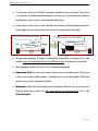
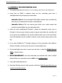
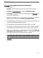
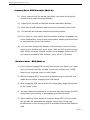
1
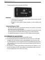
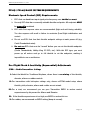
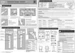
Rev 10: 4th Sept 2011
FEIYU
TECH
FY-91Q DREAMCATCHER
FIRMWARE 1.1
Multi-rotor flight stabilization & Autopilot System
Installation & Operation Guide
Guilin Feiyu Electronic Technology Co., Ltd
Rm. B305, Innovation Building, Information Industry Park, Chaoyang Road, Qixing District,
GuiLin, CN
www.feiyu-tech.com
Email: [email protected]
Guilin Feiyu Electronics Co., Ltd.
Manual Update list
Revision
Rev 8
Rev 9
Date
7th July 2011
30 August 2011
Updated
page
N/A
Page 10
Page 22 to 28
Page 29 - 30
Rev 10
4 September 2011
Page 37
Page 43
Topic updated
Completion of Manual
• Red LED Flashing
• 3 principles of autonomous flight
Firmware 1.1
• Flight parameter range
• Firmware update procedure
incorporated
• ESC Throttle Range setting
(procedural correction)
Page | 1
Guilin Feiyu Electronics Co., Ltd.
Table of Contents
Manual Update list......................................................................................................................................... 1
Basics - How the system works: .................................................................................................................... 4
Barometer and GPS & COMPASS module ................................................................................................... 4
Autopilot Function & Auto Hover ................................................................................................................. 4
Automated Return to Home ........................................................................................................................... 5
On Screen Display And Data Radio .............................................................................................................. 5
FY91Q Navigation Edition Package Content ................................................................................................ 6
System Specifications .................................................................................................................................... 6
FY-91Q Flight Modes .................................................................................................................................... 8
Flight Modes and LED Indicator ................................................................................................................... 9
Red LED: GPS Status & Vibration Indicator................................................................................................. 9
GPS & COMPASS Module Interface & Function ....................................................................................... 10
Gyro Resetting ............................................................................................................................................. 11
FY91Q Connection Interface Diagram ........................................................................................................ 12
DIP Switch Setting ...................................................................................................................................... 13
FY-91Q Power Supply Recommendations .................................................................................................. 14
FY91Q Connection to the Receiver ............................................................................................................. 14
Vibration Damping ...................................................................................................................................... 15
Quadcopter Set Up....................................................................................................................................... 17
Quadcopter FY91Q Connection Schematics ............................................................................................... 18
Y6 FY91Q Connection Schematics ............................................................................................................. 19
FY91Q Module Installation ......................................................................................................................... 21
FY91Q Preflight Inspection and Initial Testing ........................................................................................... 21
SETTING UP HOVER HOLD AND AUTOMATIC RETURN TO HOME............................................... 23
1st Principle: Hover Using Your Transmitter Trims ..................................................................................... 23
2nd Principle: The Flight Neutral Gain ......................................................................................................... 25
3rd Principle: Fy91q Learns On-The-Fly For Hover Hold ........................................................................... 26
Summary Hover Hold Procedure (Mode 2):................................................................................................ 27
Return to Home - RTH (Mode 3) ................................................................................................................ 27
GPS Detection (Home Lock) ....................................................................................................................... 29
Flight Parameter Adjustment Software ........................................................................................................ 30
FY91Q Ground Control Station Function ................................................................................................... 35
FY91Q Connection to AP117 ON SCREEN DISPLAY.............................................................................. 37
Upgrading the FY91Q Firmware ................................................................................................................. 37
FY91Q / FY90Q Basic System Requirements ............................................................................................ 42
Electronic Speed Control (ESC) Requirements: .......................................................................................... 42
Pre-Flight Check & Sensitivity (Exponential) Adjustments ........................................................................ 42
ESCs Not Arming ........................................................................................................................................ 44
Page | 2
Guilin Feiyu Electronics Co., Ltd.
Dear Pilot,
Thank you for purchasing the FY91Q multirotor flight control system from Feiyu Tech.
In order to achieve full potential and safe operation of this product, please carefully
read this manual prior to installation.
ATTENTION:
•
Set up and use of the FY91Q requires a high degree of multi-rotor flight and RC
experience.
•
If you have never flown a multi rotor aircraft before, we highly recommend that you
don’t install this equipment on your own. Please seek assistance from an experienced
multirotor pilot.
•
If you are already an experienced multirotor pilot, you will find the
installation mildly challenging but logical. Just follow the instructions as
stated in this manual and you won’t go wrong.
•
Remember, SAFETY ALWAYS FIRST.
If you need any technical support you know where to find us.
Page | 3
Guilin Feiyu Electronics Co., Ltd.
FY91Q MULTI ROTOR SYSTEM
Basics on how the system works:
•
Inertial Stabilizer: The FY91Q utilizes an attitude flight stabilization system
(AFSS) which is inertial sensing based. The system also incorporates an autonomous
flight control system.
•
The FY91Q AFSS integrates a three-axis gyroscope combined with tri-axial
accelerometers to sense and create a drift-free 3 dimensional stabilization system.
•
The FY91Q also utilizes GPS and barometric pressure sensing to obtain accurate
aircraft positioning and altitude.
•
By combining sensor data from the gyros and accelerometers, together with altitude
and GPS positioning, an accurate inertial navigation and autopilot system is formed.
Fixed positioned and altitude hover and return to home is just a switch away.
•
This product is still under intense Research and Development. FeiYu Tech has
enabled firmware upgrading via a USB-TTL Connector. As new algorithms are
developed for the autopilot system, you can download the upgraded firmware from
FY website.
Barometer and GPS & COMPASS module
v FY-91Q control module incorporates an accurate barometric pressure sensor. At
start up, the take-off air pressure is measured, providing the autopilot with an
accurate relative height data.
v The GPS & COMPASS module provided with the FY91Q Navigation Edition
consist of a three-axis magnetic sensor and high sensitivity GPS receiver. This
module enables the autopilot to sense the flight course and exact location of the
aircraft.
v Note that if the FY91Q is not connected GPS & COMPASS module, it will function
as purely as a flight stabilizer for multi rotor aircraft. The autonomous flight
system cannot be engaged.
v For the autopilot to function, the GPS Receiver must detect at least 5 satellites.
Autopilot Function
The current FY91Q firmware supports two autopilot functions; fixed altitude Auto
Hover and automated Return to Home. To enable autonomous flight, the GPS &
Page | 4
Guilin Feiyu Electronics Co., Ltd.
Compass module must be connected to the FY91Q:
Auto Hover
o 3 dimensional GPS positioning is used to automatically maintain aircraft
hover position and altitude.
o Accuracy of hover position (range) depends on wind conditions and
speed.
Automated Return to Home
o By utilizing GPS positioning, the autopilot will return the aircraft to the starting
point upon activation of the RTH Mode.
o Upon reaching the starting point (home) the autopilot will activate Hover Hold,
maintaining position and altitude while waiting for your further instructions.
o To establish the Home point, a minimum of 5 GPS satellites must be detected.
ON SCREEN DISPLAY and DATA RADIO
a. The FY91Q supports OSD data output via the UART interface.
b. By connecting this interface to the AP117 OSD, telemetric data such as GPS, flight
navigation, AHI, and autopilot modes can be displayed on your downlink video.
c. The UART Interface can also be connected to the FY-606 digital data radio system,
which establishes a bi-direction radio communication between the FY91Q and your
portable computer.
d. By uploading our Ground Control Software (GCS) (free from our website), you can
monitor your flight on the GCS map, display on-board telemetry data and control
the aircraft flight path via the click of your mouse.
Page | 5
Guilin Feiyu Electronics Co., Ltd.
FY91Q Navigation Edition Package Content
FY-91Q Navigation Edition contains the following hardware:
• FY-91Q control module x 1;
• FY91Q RC receiver connection cable pack x 1;
• GPS & COMPASS Interface module x 1;
• FY GPS Receiver x 1
• Double-sided adhesive Damper pad x 1;
• Self-adhesive Velcro sponge x 2;
• GPS connecting wires x 1
• Jumper for gyro resetting x 1
SYSTEM SPECIFICATIONS
FY-91Q Module
Operating voltage
4.0~6.0 Volt
Current consumption
Dimensions
Weight (not including wires)
50mA (5V input)
55 x 33 x 20 mm
20g
Operating Temperature
The maximum allowable rotation rate
-25°C~ +70°C
3 rotations per minute
GPS & COMPASS INTERFACE MODULE
Operating voltage
Current consumption
Dimensions
Weight (not including wire)
Temperature range
4.0~6.0 Volt
60mA (5V input)
55 x 33 x 20 mm
20g
-25°C~ +70°C
Page | 6
Guilin Feiyu Electronics Co., Ltd.
APPLICABLE AIRCRAFT MODELS
The FY91Q can be installed and flown it the following multi-rotor aircraft:
v 4 motored Quadcopters;
v Tri-axial rotory aircraft with 6 motors (Y6)
v Tri-axial rotory aircraft with 4 motors (Y4)
v Six-axial multi-rotor aircraft (Hexacopters)
Any other configuration, please contact us for confirmation: [email protected]
REMOTE CONTROL SYSTEM COMPATIBILITY
FY-91Q have been tested to work with the following RC systems:
•
Robbe-Futaba PPM / PCM 1024 / PCM G3 mode, 2.4 GHz systems
•
Graupner/JR PPM 8, PPM 12, SPCM mode
•
MPX PPM8, PPM 12 with UNI mode
•
Any remote control system using the standard of 1.5 ms neutral position.
Page | 7
Guilin Feiyu Electronics Co., Ltd.
FY-91Q FLIGHT MODES
1.
FY-91Q has three operating Flight Modes, which is selected by using any free channel
on your RC receiver.
2. You can set the 3 modes via a 3 way switch or use a dial knob. Example:
1
2
3
3. However, since switch flight modes is required during the setting for autonomous
flight, we highly recommend that you use the 3-way switch.
Receiver PPM
signal level
FLIGHT MODES
900-1200µs
1200-1800µs
1800-2100µs
Mode 3:
Return to Home
Mode 1:
Stabilizer Mode
Mode 2:
Automated Hover Hold
Mode 1: Stabilized Mode
In this mode, the FY-91Q will stabilize the multi-rotor aircraft for normal flight. Full
flight direction control is given to the pilot.
Mode 2: Automated Hover Hold.
In Hover Hold, the aircraft will maintain hover altitude and position. The GPS and
Compass Module must be connected to the FY91Q with at least 5 GPS satellites
detected.
Mode 3: Automated Return to Home Mode.
Activating this mode will automatically initiate the aircraft to fly back to the Home
point. Requires the GPS and Compass Module to be connected to the FY91Q with at
least 5 GPS satellites detected.
Page | 8
Guilin Feiyu Electronics Co., Ltd.
Flight Modes and LED Indicator
1. To indicate the flight modes of the FY91Q, the Blue LED light will flash:
Flight Modes
Blue LED
Flashing
Mode 2
(Hover Hold)
Continuous flashing
Mode 1
(Stabilized Mode)
LED Always On
Mode 3
(RTH Mode)
Three intermittent
flashing
GPS Status & Vibration LED Indicator
The GPS connection status & vibration level is indicated by the Red LED Flashing:
GPS & Vibration
Status
Severe
vibration*
GPS & COMPASS
module not connected
5 GPS Satellite detected
(Home position Locked)
Red LED
Continuous
None
Double Intermittent
flashing
flashing
(LED light OFF)
Flashing
* In case severe vibration is detected reduce your aircraft vibration levels or improve
vibration damping for the FY91Q mounting.
Page | 9
Guilin Feiyu Electronics Co., Ltd.
GPS & COMPASS Module Interface & Function
1.
To enable the autopilot options you must have the GPS & COMPASS module
connected to the FY-91Q.
Direction of flight
Red LED flashes
when working.
Green LED flashes
when connected to
GPS.
FYGPS
Connected to the
FY-91Q
2. IMPORTANT: The GPS & COMPASS Module is
sensitive to vibration. Please use the included
damper sponge when mounting this module.
3. WARNING: Wrong installation of the GPS &
COMPASS Module will result in inconsistent
performance and even autopilot malfunction.
4. GPS & COMPASS module is utilizes a ceramic passive GPS Receiver. This FY-GPS
Receiver must be installed face up as indicated on the sticker.
5. Do not allow any metal or carbon fiber material to block or shield the FY-GPS
from detecting GPS satellite signal.
6. WARNING: The GPS & COMPASS Module is very sensitive to metal, magnets,
electromagnetic fields and radiation. Keep such materials as far away from the
Module as possible. Example: main power cables, servo and servo wires, video
transmitters, ESCs, motors, etc. all can affect the GPS & Compass Module.
Page | 10
Guilin Feiyu Electronics Co., Ltd.
GYRO RESETTING
1.
Out of the box, the FY-91Q has already been initialized and is ready to use.
2. Generally the FY91Q gyros do not need to be re-set, but under certain conditions
initializing the gyros does become necessary:
a) The unit has not be used for a long time,
b) Extreme change in environmental temperature in excess of 30oF.
c) FY91Q fails to start the motors
d) The Red LED light of the FY91Q is blinking continuously
If any of the above has occurred, please proceed with the initialization process.
3. Note that routine gyro resetting is not necessary.
4. Gyro Resetting Process
a. The FY91Q does not have to be leveled, however please ensure it is not moved,
shaken or experience any kind of vibration during the initialization process. If
movement / vibration did occur, please repeat the procedure.
b. Install the gyro initialization jumper as shown below:
FY-91Q Module
c. Supply power to the module and ensure it remains stationary for at least 20
seconds.
d. The red LED light will flash followed by OFF after approximately 20 seconds. The
initialization process is complete.
e. Disconnect the power supply and unplug the jumper (please keep in a safe place
for future use).
Page | 11
Guilin Feiyu Electronics Co., Ltd.
FY91Q Connection Interface Diagram
Arrow must point towards
aircraft direction of flight.
Flight Course (Yaw)
sensitivity knob
Roll sensitivity knob
DIP switchs
(mode selection)
Pitch sensitivity knob
GPS status and
Vibration level LED light
indicator. (Red)
Flight mode LED
indicator. (Blue)
Jumper installed
during gyro
initialization.
ESC 5 and ESC 6
Connection
See page: 18
I
II
Do not insert
jumper during
normal use.
III
Interface Pin
Panel (see below)
IV
8
7
6
5
4
3
2 1
Interface Pin Panel Connection:
8
7
6
5
4
3
2
1
GND
Null*
P1
P2
GND
Power
TX0
RX0
I
ESC4
ESC3
ESC2
ESC1
GND
Power
TX1
TX1
II
Null*
Null*
Null*
Power
Input
Rx free
channel
(Switch 1)
Rx Throttle
(Ch 3)
Rx Ele
(Ch 2)
III
GND
GND
GND
GND
GND
Rx AIL
(Ch 1)
No Pin
IV
Rx Rud
(Ch 4)
Power
Null* : Do not connect anything on these pins (leave open).
Page | 12
Guilin Feiyu Electronics Co., Ltd.
DIP SWITCH SETTING
The FY91Q utilizes a Dip Switch system for model selection, via Dip switch No. 2 to 4:
Switch Position
1
2
3
4
ON
(Factory use
only)
Flight mode
debugging
X-format
Y6 flight
mode
OFF
Always OFF
Normal flight
mode
Cross
format
X4 flight
mode
Switch Diagram Reference: the switches below are in the OFF POSITION:
ON
OFF
1
2
3
4
Example:
a. Dip Switch position for X-TYPE QUADCOPTER:
1 = OFF
ON
2 = OFF
3 = ON
OFF
4 = OFF
1
2
3
4
b. Dip Switch position for CROSS-TYPE QUADCOPTER:
1 = OFF
2 = OFF
ON
3 = OFF
OFF
4 = OFF
1
2
3
4
Page | 13
Guilin Feiyu Electronics Co., Ltd.
c. Dip Switch position for CROSS-TYPE Y6:
1=
2=
OFF
OFF
3=
4=
OFF
ON
ON
OFF
1
2
3
4
d. Dip Switch position for Hexa-Copter:
1 = OFF
2=
3=
OFF
OFF
ON
4=
ON
OFF
1
2
3
4
FY-91Q Power Supply Recommendations
1.
The FY91Q input power supply can range from 4 to 6 volts.
2. More importantly, the current input and voltage must be stable.
You may use an external BEC with 3A output or use ESC with good quality 3A BEC.
3. We recommend that power is supplied via the ESC 1 power input pin
4. Your radio receiver power supply is via the FY91Q Aileron cable (channel 1).
FY91Q Connection to the Receiver
1.
The FY91Q is connected to the receiver via this cable bundle:
Page | 14
Guilin Feiyu Electronics Co., Ltd.
2. The wire colors will help you trace the connection to your Receiver:
Wire Colour
White (bundled with red
and black)
Orange
Green
Yellow
Brown
Receive Channel
Aileron
Channel 1
Elevator
Throttle
Rudder
Any free channel controlled by
3-way switch or dial (refer page 6)
Channel 2
Channel 3
Channel 4
Channel 5
(example)
3. Note that the open channel for Switch 1 (SW 1) must be controlled by either a
3-way switch or a dial on your radio transmitter. SW1 controls the Flight Modes of
the FY91Q.
VIBRATION DAMPING
a) The FY91Q flight controller algorithms can filter and operate under normal
vibration levels, however if the vibration and shock experienced by the onboard
sensors is too extreme, stabilization can fail and the system can shut down
altogether.
b) Because of this, to achieve the best stabilization and flight performance out of
the FY91Q, you must minimize the amount of vibration on the aircraft as best
you can.
c) Examples of vibration reduction steps that can be taken:
i) Ensure your motors are mounted properly and squarely.
ii) Balance your propellers regardless of the manufacturer’s claim of perfect
balance out of the factory.
iii) Balance your motor bell housing (if possible).
iv) Ensure rigidity of your frame (will not flex with motor rotation).
v) Use appropriate propeller length and pitch for the weight of your aircraft.
Page | 15
Guilin Feiyu Electronics Co., Ltd.
d) The FY-91Q is supplied with the shock absorbing mount and double-sided foam
padding dampers. Please use them as shown below:
CHECKING FOR VIBRATION
a) Install the FY91Q as per the recommendations of this manual, including
directions of propeller rotation.
b) Remove the connection to the GPS & Compass Module.
c) Throttle up in Mode 1 (Stabilized Mode) but do not take off!
d) Observe the red LED on the FY91Q module.
e) If the red LED light remains OFF, this indicates your aircraft vibration level is
acceptable.
f) If instead the red LED light goes ON and remains lighted, your aircraft does not
meet the vibration level requirement. Please reduce the onboard vibration level.
Page | 16
Guilin Feiyu Electronics Co., Ltd.
QUADCOPTER SET UP
X-Type Layout
1
4
1
2
3
4
X-Type QuadCopter Layout:
1 = ESC 1
2 = ESC 2
3 = ESC 3
4 = ESC 4
2
CCW
CW
CCW
CW
cw = clock wise
ccw = counter clockwise
3
Cross Type Layout
1
1
2
4
3
2
3
4
- Type Quad Layout:
1 = ESC 1 CCW
2 = ESC 2 CW
3 = ESC 3 CCW
4 = ESC 4 CW
cw = clock wise
ccw = counter clockwise
Page | 17
Guilin Feiyu Electronics Co., Ltd.
QUADCOPTER FY91Q CONNECTION SCHEMATICS
GPS
GSP&CPMPASS
PC setting
AP117 OSD
Data Radio
CH5
RUD
E
S
C
4
E
S
C
3
E
S
C
2
E
S
C
1
THR
ELE
AIL
Page | 18
Guilin Feiyu Electronics Co., Ltd.
Y6 FY91Q CONNECTION SCHEMATICS
2
3
6
5
1
2
3
4
Y6 SCORPION FLYER
1 (top)
= ESC 1
2 (top)
= ESC 2
3 (top)
= ESC 3
4 (bottom) = ESC 4
5 (bottom) = ESC 5
6 (bottom) = ESC 6
4
CW
CW
CW
CCW
CCW
CCW
cw = clock wise
ccw = counter clockwise
1
Y-Cable
(included)
E S C 6(P2)
E S C 5(P1)
GPS
GSP&CPMPASS
PC setting
AP117 OSD
Data Radio
CH5
RUD
E
S
C
4
E
S
C
2
E
S
C
2
E
S
C
1
THR
ELE
AIL
Page | 19
Guilin Feiyu Electronics Co., Ltd.
FY91Q Hexa Copter Setup
E S C 6(P2)
GPS
Y-Cable
(included)
E S C 5 (P1)
GSP&CPMPASS
PC setting
AP117 OSD
Data Radio
CH5
RUD
E
S
C
4
E
S
C
3
E
S
C
2
E
S
C
1
THR
ELE
AIL
5
3
1
2
3
4
6
2
1
4
X - Type Hexa Layout:
1 = ESC 1 CW
2 = ESC 2 CW
3 = ESC 3 CW
4 = ESC 4 CCW
5 = ESC 5 CCW
6 = ESC 6 CCW
CW = clock wise
CCW = counter clockwise
Page | 20
Guilin Feiyu Electronics Co., Ltd.
Direction of flight
FY91Q Module Installation
1.
FY91Q has an arrow indicator on top. Please ensure this arrow is pointed towards
the direction of flight.
2. Installed the module horizontally, and as close as possible to the aircraft center. A
more centered installation will result in more stable drift free hover.
3. The FY91Q sets its own benchmark of what is ‘horizontal’. Install the module based on
the hover characteristics of the aircraft in Mode 1 (Stabilized Mode). Shimming the
module may be required to get the aircraft to hover perfectly.
FY91Q Preflight Inspection and Initial Testing
Pre-flight testing for aircraft control:
1.
Remove all propellers.
2. Activate throttle to start up the motors. Check the rotation direction of each motor
and make sure it is turning in the right direction.
3. Re-Install propellers.
4. Check again that the rotation is correct.
5. Check the FY91Q sensitivity control knobs. Please ensure the dials are beyond 12
o’clock. Anything less than that may result in no flight stability for this first flight.
Page | 21
Guilin Feiyu Electronics Co., Ltd.
6. Tie down test: Before proceeding, we highly advise that you tie down the aircraft
to the ground to prevent any possibility it going out of control during this initial
flight tests. Safety first.
7. First test lift off: Advance your throttle stick, but do not take off (usually around
30% throttle). Let the aircraft float just enough so that you can see the aircraft
reaction as you move your Aileron, Elevator and Rudder sticks.
8. If the control movement is reversed, just reverse the channel on your RC
transmitter.
9. After step 8, you can take off higher. If the aircraft hovers well, you can proceed to
remove the aircraft from the tie down test.
10. Observe the flight for stability and oscillations as the aircraft hovers higher.
11. If you feel there is not enough stability (e.g. excessive drifting), you can increase the
sensitivity of the three dials.
12. If there are rapid oscillations, reduce the corresponding sensitivity knob.
13. More fine tuning adjustment can be done via the FeiYu software (you will need the
TTL-USB cable for this).
Pre-flight Debugging
1. If your aircraft fails to lift off and hover for the initial pre-fight tests, please check the
following:
a) Check the ESC connections are all correctly plugged in. Take time to check and
re-check that each ESC has been plugged in and that the plugs are correctly
placed.
b) Please ensure there is no short circuit of the power (positive) and GND wires.
Short circuits can damage the internal processor chip beyond repair (voiding all
warranty).
c) Check that all motors are rotating in the direction noted in this manual.
d) Ensure you have selected mid or high timing for your ESC (if you are not using FY
ESCs).
Page | 22
Guilin Feiyu Electronics Co., Ltd.
FY91Q FIRMWARE 1.1
SETTING UP HOVER HOLD AND AUTOMATIC RETURN TO HOME
a) Note: commissioning the Hover Hold and RTH Mode require a certain degree of
flying skill. You may need a friend’s assistance to carry out the entire procedure.
b) Setting up involves:
i)
ii)
iii)
i)
Understand the 4 Principles of FY91Q Autonomous Flight
GPS & Compass Set Up (Field Calibration)
GPS Satellite Detection
The 3 Principles of FY91Q Autonomous Flight
The FY91Q has three unique autonomous flight principles which is different from any
other multirotor system.
Failure to understand these 3 Principles will result in failure
to achieve autonomous flight.
1ST PRINCIPLE: HOVER USING YOUR TRANSMITTER TRIMS
1.
The FY91Q is a 3 gyro / 3 accelerometer stabilizer system mounted on a flat
platform (board). This platform is mounted in an aluminum box.
2.
The positioning of these 6 sensors varies from one FY91Q module to another (no
two modules are exactly the same). Furthermore, mounting of the module on the
aircraft may result in tilting to one side.
3.
Therefore, a less than leveled Axis will always occur. Example:
Aircraft will drift to the right.
Left
FY91Q tilted left
FY91Q Axis not leveled:
Right
Left
Aircraft will drift to the left.
FY91Q tilted right
Right
Page | 23
Guilin Feiyu Electronics Co., Ltd.
4. To solve this, install your FY91Q as leveled as possible on your aircraft. Then hover
your aircraft in Stabilized Mode (Mode 1) and use your transmitter trims (Aileron
and Elevator only) to get it to hover almost hands free.
5. If you note too much trim is used, reinstall your module by shimming the mounting.
Hover again and you should note a reduction in trimming used. Example:
Aircraft will drift to the right.
Left
FY91Q tilted left
Add shimming to level the module
Right
FY91Q leveled
6. By the same principle, if there is a directional wind which is causing drift to the
aircraft, use your transmitter Aileron and Elevator trims to counter this wind drift.
7. Note that every flight will require some trimming adjustment.
8. Important Note: As much as possible, do not use your Rudder trims. Keep your
rudder trims in the middle position. (If rudder trim is not in the middle, RTH flight
direction may not be straight line flight).
9. Reminder: Other than the throttle stick to maintain altitude, you do not use your
sticks to hover the aircraft. Use only your Aileron and Elevator trims. This is the
First Principle.
Page | 24
Guilin Feiyu Electronics Co., Ltd.
2ND PRINCIPLE: THE FLIGHT NEUTRAL GAIN
1.
The 2nd principle does not require you to do anything, other than to fully understand it.
2. Every time an FY91Q is airborne, there are two controlling gains that is
interdependent and yet opposing to each other:
Controller Gain 1: The automated FY91Q flight controller gain, produced by
the 6 sensors to maintain the aircraft in a leveled state.
Controller Gain 2: The user manual gain (that’s you), which controls the
aircraft in manual flight via your transmitter sticks.
3. After you have implemented Principle 1 (hover by transmitter trims), then in
Principle 2, the two gains function purely to oppose each other; the controller will
try to oppose any instability of the aircraft, while the pilot (you) via the transmitter
stick, will make the aircraft ‘unstable’ so that it can be moved to any position in the
sky.
4. If you have fulfilled the 1st Principle, letting go of the transmitter sticks (Aileron,
Elevator, Rudder), will return the aircraft to a leveled flight state.
5. This leveled flight state with no input from the pilot is called the Flight Neutral
Gain or Neutral Value.
6. MOST IMPORTANTLY, note that other than your throttle stick, when in Flight
Neutral Gain your transmitter sticks are ALL in the middle position.
7. Pause here and think about it.
8. Note that Throttle control is fully manual at all times. Flight Neutral Gain does not
involve the throttle channel.
Page | 25
Guilin Feiyu Electronics Co., Ltd.
3rd Principle: FY91Q LEARNS ON-THE-FLY FOR HOVER HOLD
1.
A quick Recap:
Principle 1 = FY91Q can hover using only trims. Throttle maintains altitude.
Principle 2 = Hovering Hands free is the point of Flight Neutral Gain
2. 3rd Principle = the FY91Q will ‘learn’ your Flight Neutral Gain every time you
activate Hover Hold (Mode 2).
3. However, this ‘learning’ process can only occur if you release all control sticks
(Aileron, Elevator, Rudder) and leave them in the middle position.
4. The Flight Neutral Gain (hands free hover) must be achieved before the FY91Q can
‘learn’ the hover setting and engage Hover Hold.
5. The learning process and engaging Hover Hold takes about 1 to 2 seconds.
6. The moment you input any control movement via Aileron / Elevator or Rudder,
FY91Q will disengage Hover Hold and the aircraft is in your manual control again.
7. Please also note that when you engage the Hover Hold Switch, FY91Q also
acknowledges your throttle level. Therefore, it is critical that you engage
Hover Hold only after you have set the throttle level for hovering.
8. If you engage Hover Hold while the aircraft is descending (throttle too low) or
ascending (throttle to high), FY91Q will set that throttle level as the hover throttle
level. This will result in your aircraft continuing its descent or ascent movement in
Hover Hold.
Page | 26
Guilin Feiyu Electronics Co., Ltd.
Summary Hover Hold Procedure (Mode 2):
(1) Hover your aircraft for hands free flight. Use trims to bring the
aircraft into a good hovering attitude.
(2) Adjust your throttle so that the aircraft maintains altitude.
(3) After the aircraft attains hands free hover, activate Hover Hold.
(4) The aircraft will maintain altitude and hold position.
(5) If you wish to move Hover Hold to another location, disengage the
Hover Hold switch; move to the new location, attain good hover and
re-activated the Hover Hold switch.
(6) You can also change the altitude of the aircraft in Hover Hold by
moving your throttle stick up or down. But you will need to bring it
back to the hovering throttle position to re-engage Hover Hold. If
you cannot remember this position, carry out no. (5) above.
Return to Home - RTH (Mode 3)
1) If you wish to engage RTH at any time during your flight, you must
carry out Hover Hold for at least 2 seconds, so that your FY91Q
learns your hovering trims for level flight.
2) Before engaging RTH, as much as possible bring the aircraft to a
stable hover before engaging the RTH switch.
3) After engaging RTH, the aircraft will immediately begin flying back
to the ‘home’ point.
4) You can change the altitude up or down at any time during the RTH
procedure by increasing or decreasing your throttle level.
5) Upon reaching Home position (location where GPS lock occurred)
the aircraft will automatically engage Hover Hold. Bring your
throttle stick to the hovering level to maintain Altitude and Position
hold.
Page | 27
Guilin Feiyu Electronics Co., Ltd.
GPS & COMPASS MODULE SET UP (MANGETOMETER CALIBRATION)
1.
The GPS & COMPASS Module contains an internal three-axis magnetometer. This
module senses the earth's magnetic field, and uses this reading to accurately
measure the aircraft direction of flight.
2. The magnetometer sensor is very sensitive to metallic objects and electric fields.
Keep such objects as far away from the module as possible.
3. Before each flight, it is best to do a field calibration. With practice it is very easy to
do (takes only 20 seconds).
4. Field calibration enables the GPS & Compass Module to calibrate for the
environment in which it is installed.
5. Field calibration should also be done if new equipment is installed which may affect
the magnetic field around the aircraft.
6. Field calibration process:
a) Place the aircraft on flat ground.
b) Continuously change (toggle) the flight modes between Mode 1 (Stabilized
Mode) to Mode 2 (Hover Hold) six times:
(1) balance mode -> Hover Hold – (2) balance mode -> Hover Hold –
(3) balance mode -> Hover Hold – (4) balance mode -> Hover Hold –
(5) balance mode -> Hover Hold – (6) balance mode
c) Observe the blue LED go OFF after you toggle 6 times. This indicates the
FY91Q has entered the Field Calibration Mode.
d) After the Blue LED goes OFF, move the aircraft slow and steady in a clockwise
rotation one and a half times. The rotation should be done slowly, taking
Page | 28
Guilin Feiyu Electronics Co., Ltd.
approximately 15 seconds to complete. If you do it too fast, calibration will fail
(Blue LED will not light up), and you have to do it all over again.
e) After this rotation, the blue LED will light up again, indicating Field Calibration
is complete.
f) Proceed to into GPS Detection.
ii) GPS DETECTION (HOME LOCK)
a) GPS is required to enable autopilot flight positioning.
b) Ensure you are outdoors to maximize GPS satellite detection (minimum 5
required).
c) Upon power up, the FY91Q will automatically search for GPS satellites.
d) Upon detecting 5 satellites, the red LED will begin flashing twice
continuously, indicating GPS Home Position has been locked.
e) You can safely fly the FY91Q system without GPS locking ‘home’ position
(red LED flashing twice). However, both Hover Hold and RTH autonomous
flight cannot function.
f) Without GPS lock, the FY91Q can only hold altitude if Hover Hold is
activated. Position hold cannot be activated, and therefore the aircraft will
drift randomly.
g) If during the RTH function GPS lock is lost, the aircraft will stop moving and
begin to drift randomly. However, it can still fly while maintaining altitude.
Page | 29
Guilin Feiyu Electronics Co., Ltd.
FLIGHT PARAMETER ADJUSTMENT SOFTWARE
The FY Tech FY91Q Parameter settings interface is as show below:
Flight Parameter Adjustment Software – SAFETY FIRST!
1. The default FY91Q settings have been adjusted for optimal stability and flight
performance. The flight parameter adjustments provided via the FY Tech Flight
Parameters Setting software should only be done by very experienced
multirotor pilots who need to further fine tune the aircraft characteristics.
2. We do not recommend adjusting the flight parameters without a specific fine
tuning target.
3. Safety Warning 1: A Wrongly Adjusted Flight Parameter Setting may result in
extreme aircraft instability and crash. Do a tie down test when adjusting Flight
Parameters for the first time.
Page | 30
Guilin Feiyu Electronics Co., Ltd.
4. Safety Warning 2: If you are powering the FY91Q via your onboard BEC, make
sure you take off the red wire as shown below. Failure to do so may result in
damage to both your computer and FY91Q. Additionally, if you are powering the
FY91Q via your ESC BEC, make sure you tie down your aircraft or take off the
propellers to prevent possible accidental injuries.
Remove Red wire if using the on
board ESC BEC to power up the
FY91Q. Failure to do this can result
in damage of your PC and FY91Q.
5. Hardware requirements:
a) Portable PC / Laptop with USB port.
b) USB – TTL Cable
c) Download and install the USB-TTL Drive. Download site:
http://shop.fyetech.com/dl/ttldriver.rar
d) Download and install the FY91Q Parameters Setting Software. Download site:
(Link to be released later)
Page | 31
Guilin Feiyu Electronics Co., Ltd.
6. Setting adjustment procedure:
a) Connect USB-TTL cable to the computer.
b) Connect the USB TTL cable to the FY91Q UART data port as shown below:
FY-91Q Module
USB-TT
FY91Q Software
c) Note the range of values that you can put inside the boxes is 0.6 x to 1.8 x the
default value. Example; for the first box, the default value is 35.
The minimum value for this parameter is 35 x 0.6 = 21.
Maximum value is 35 x 1.8 = 63
d) Open the FY91Q Parameters adjustment software. Select the appropriate USB
port number (check via your computer Device Manager) and set the baud
rate to 19200.
Page | 32
Guilin Feiyu Electronics Co., Ltd.
Click "Open" to connect to your FY-91Q.
e) Click “Read” to see the existing parameters:
f) Flight parameter settings:
Pitch
control
Pitch
level
coefficient
This setting controls the
amount of pitch
automatic recovery.
Stability Continue
Stability coefficient
Stability level
adjustments. Reduce
until oscillations
stops.
A higher value makes the
respond stronger to prevent
pitch angle changes.
Generally larger / heavier
aircraft require higher value.
A higher value makes the
respond stronger to prevent
roll angle changes.
Generally larger / heavier
aircraft require higher value.
A higher value makes the
respond stronger to prevent
heading (yaw) changes.
Roll
control
This setting controls the
amount of roll
automatic recovery.
Stability level
adjustments. Reduce
until oscillations
stops.
Heading
control
This setting controls the
amount of heading
(yaw) lock stability.
Controls the amount
of integral yaw
control. Too high will
lead to oscillations.
Page | 33
Guilin Feiyu Electronics Co., Ltd.
g) Additional setting adjustments:
a. Altitude compensation: This parameter controls the sensitivity of the FC to
automatically increase or decrease throttle level to compensate for altitude loss
during aircraft tilt recovery. Example: If you observe the aircraft lose altitude during
tilt recovery, increase the value of this parameter.
b. Speed control: Increase or decrease this value to adjust the sensitivity to
forward flight (speed) of the FC.
c.
PID Settings:
X
P
Control the amount of
lateral deviation.
Y
Control the amount of
vertical deviation
Height
control
Control the amount of
height variation
I
Integral control the
amount of lateral
deviation.
Integral control the
amount of vertical
deviation
Integral control the
amount of height
variation
D
Control the amount
of lateral deviation
change
Control the amount
of vertical deviation
change
Height deviation
change degree of
control.
Page | 34
Guilin Feiyu Electronics Co., Ltd.
h) After setting adjustment, confirm the new parameters by clicking the “Set” button.
Clicking the “Set” button will send the new setting to the FY91Q.
i) Click to “Read” button to confirm the changes have been saved.
j) Finally, click the "Write to FY-91Q" button to permanently save the new settings in
the FY-91Q. If this button is not pressed, the new parameters will be lost when you
power-down the FY91Q.
k) Return to Default Setting
If you feel at any time you wish to return to the factory settings, simply click on
“Restore Default Parameters”. The factory default settings will be displayed. Click
on all the “Set” buttons, before pressing “Write to FY-91Q”.
FY91Q Ground Control Station Function
1.The FY91Q the UART interface can be connected to the FY digital Data Radio,
such as FY606 (2.4 Ghz) and FY602 (433 MHz) for bidirectional
communication between your field PC (GCS) and the FY91Q autopilot.
2.
You will require to download the latest FY-GCS software to utilize the GCS
function of the FY91Q.
3.
FY-GCS enables you can display the onboard autopilot telemetry data on to
your GCS display, including the GPS position of the aircraft on Google Map.
4.
You can remotely adjust the flight parameters of the FY91Q via the GCS
software.
We will release more information about this feature in future FY91Q manual
updates.
Page | 35
Guilin Feiyu Electronics Co., Ltd.
5.
Data radio Parameters:
FY91Q interface panel have 4 Pin for UART
GND, Power, TX1, RX1
Baud rate
19200
Interface characteristic
TTL
ON BOARD AIRCRAFT
FY-91Q Module
GN
GN
Powe
5V
FY606
TX1
RX
Data Radio
TX
RX
Two Way Communication
GROUND CONTROL STATION
FYGCS
GN
GND
5V
5V
FY606
TX
RX
Data radio
RX
TX
USB-TTL
PC
6.
Refer to FY606 Manual on more details on the FY606 (to be updated).
7.
Refer to FYGCS Manual on more details of the FYGCS (to be updated).
Page | 36
Guilin Feiyu Electronics Co., Ltd.
FY91Q Connection to AP117 ON SCREEN DISPLAY
1. You can connect the FY91Q to the AP117 OSD module to display the telemetry data
onto your On Screen Display.
2. Connection is as shown below:
FY-91Q Module
1. Updating the Firmware
Data port to connect to the
AP117
Refer to AP117 Manual on more details of the display.
http://shop.fyetech.com/dl/ap117.pdf
Flight Modes
AP117 Display
Mode 1
Mode 2
Mode 3
(Stabilized Mode)
(Hover Hold)
(RTH Mode)
ABM
FAF
RTL
UPGRADING THE FY91Q FIRMWARE
WARNING – Please read the following before doing any firmware upgrading:
A) Remove the FY91Q from all connections (Remove ESC/RC wires).
B) Ensure that during the Firmware upgrading process is not disrupted (e.g. moving your USB
cable around resulting is lost connection). Disruption during the upgrading process can damage
your FY91Q processor.
C) If you are using a portable computer, make sure you have enough power to carry through the
upgrade process. This is to prevent B) above.
D) Follow the steps below EXACTLY CHRONOLOGICALLY. If you skip any step, firmware
upgrade will fail.
THE PROCEDURE
1. Download the software from FY websites. Install it onto your desktop (or a designated folder).
You will also require to download both the firmware upgrade program and the require
firmware (.bin file) :
Page | 37
Guilin Feiyu Electronics Co., Ltd.
DO NOT OPEN THE FIRMWARE PROGRAMM YET.
2.
If you have not done so, please install the USB TTL Cable driver from FY websites. The
computer will not recognize the USB TTL Cable if the proper driver is not installed.
3.
Connect the USB-TTL cable to the computer. Note – do
not connect the FY91Q yet.
4. Open the FY Firmware program:
5.
Select the right Com port number, and select 19200 as the
baud rate.
6. If you do not know which COM port number, do the following:
Click your control panel:
Click on system:
Hardware, click Device Manager:
Check the COM Port number for Prolific USB-to-Serial Comm Port:
Note COM number.
Page | 38
Guilin Feiyu Electronics Co., Ltd.
Select the above COM number onto your Firmware upgrade
program:
7.
Click “Open port” button. If the COM port is right, the word “Open Port” will change to “Close
Port”. Check your COM port number again if this fails.
8. Plug the Serial connector to the FY91Q [-,+, UART] port.
Please ensure the polarity of your wires is correct. The RED wire is “+”. Wrongly
connecting the polarity will damage your FY91Q.
9. After plugging in the FY91Q, you will see “Connect success!”. After about 5 seconds this note
will disappear. THIS IS NORMAL. If connection is not successful, go to step no. 1 (repeat).
After 5 seconds:
Page | 39
Guilin Feiyu Electronics Co., Ltd.
10. Select the firmware to be uploaded:
The firmware will be noted on
the screen. This note will
disappear after 5 seconds.
11. Press the Start Upgrade button:
12. Immediately after pressing ‘Start Upgrade’, the software will show blocks of firmware being
sent to the FY91Q. A total of 61 blocks will be sent.
Page | 40
Guilin Feiyu Electronics Co., Ltd.
DO NOT DISRUPT THIS PROCESS. DOING SO WILL DAMAGE YOUR FY91Q.
13. After completion of the firmware upgrade, the software will show successful upgrade:
14. Unplug the FY91Q. Label the Version that you have uploaded and test fly the new firmware.
Page | 41
Guilin Feiyu Electronics Co., Ltd.
FY91Q / FY90Q BASIC SYSTEM REQUIREMENTS
Electronic Speed Control (ESC) Requirements:
1.
ESCs that can handle an input signal pulse frequency over 400Hz is a must.
2. Use only ESCs that has a manually settable throttle end points. All endpoints MUST
be manually matched.
3. ESCs with Fast response rates are recommended (high and mid timing settable).
Too slow response will result in failure to maintain Quad flight stabilization and
control.
4. Do not use ESCs that lose their throttle endpoint settings at each power off (e.g.
Castle Thunderbird series).
5. Do not use ESCs that must be "armed" before you can set the throttle endpoints
(Castle Thunderbirds, Hobby King SS ESCs, etc.). With this ESC type, you must
power up all motors and go to full throttle to set the endpoints, making it
impossible to use on multirotors.
Pre-Flight Check & Sensitivity (Exponential) Adjustments
STEP 1 - Radio Transmitter Settings
I. Select the Model for Traditional Airplane, where there is no mixing of the throttle,
elevator, aileron or rudder controls.
II. For transmitters with helicopter settings only, choose mCCPM model setup where
throttle, pitch, elevator, aileron and rudder are not mixed.
III. For a start, we recommend you use your Transmitter EXPO to reduce control
responsiveness by 50 percent for Aileron and Elevator.
IV. If the throttle responsiveness is too high, use EXPO to reduce this too.
V. For rudder, we recommend no EXPO setting (keep at normal).
Page | 42
Guilin Feiyu Electronics Co., Ltd.
STEP 2 – Matching ESC End Points (Throttle Range)
(a) The FY91Q controls your aircraft by sending controlling signals to your ESCs.
(b) For the FY91Q to be able control your aircraft stability and flight, a throttle base
point must be established. This base point is your ESC throttle minimum point.
(c) Therefore, only use ESCs that you can manually set the throttle endpoints
(minimum and maximum throttle range). All endpoints MUST be manually
matched.
(d) To manually match your ESC endpoints, refer to your ESC Manual.
(e) As a general rule the setting of your ESC throttle range should be done
individually. i.e. connect every single ESC directly to your RC Receiver
channel 3 and set the minimum and maximum throttle range as noted in
your ESC Manual.
(f) After setting the minimum and maximum throttle range, install the ESCs to the
FY91Q as noted in this manual.
(g) On Powering up your aircraft, you should observe that ALL your ESCs must arm
at the same time as noted by the ESC simultaneous arming beep.
(h) Proceed with flight tests as per this manual. Carry out a tie down test if you are not
sure of your aircraft flight characteristics.
Page | 43
Guilin Feiyu Electronics Co., Ltd.
ESCs Not Arming
1. Many types of ESCs have an arming protection set up where they expect to see an
incoming signal as soon as they are powered up. If the ESC do not ‘see’ this input
signal, it will automatically inhibit the arming process.
2. Upon powering up, the FY91Q takes about 1 to 2 seconds to initialize. During this
time, signal is not immediately sent to the ESCs. Due to (1) above, the ESC will not
arm even after the FY91Q begins sending signal to the ESC.
3. As a result, the ESC refuses to arm.
4. To confirm this, carry out the following:
(a)
(b)
(c)
(d)
Remove all your ESC red wire (positive) connection to the FY91Q.
Install an external BEC (at least 3A output).
Turn ON your Radio Transmitter and set the minimum to -30%.
Power up the FY91Q and your RC receiver via the external BEC, but NOT
the ESCs.
(e) After the FY91Q initializes, power up your ESCs.
(f) Decrease your throttle to - 100 until the ESC arms.
(g) This proves your ESC has the delayed activation protection.
5. An easy set up to solve this is to have a two plug power up system. i.e. power up
your BEC first, before powering up your ESCs.
-
END OF MANUAL -
Page | 44