1
Installing the Components
In-Filter Location Using Probe Mounts—
The most common place for probe location is
in the filter. Installing probes in a filter or
sump requires that the probes be secured
using probe mounts that attach to the back
of the filter so the probes are only halfimmersed in the water, (See Figure 2.2.)
When placing your probes, be sure that
there is adequate water flow over the probe
tips at all times. The pH and ORP probes
must be placed within 6 inches of the
Temperature Probe.
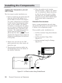
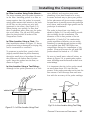
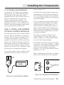
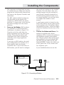
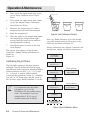
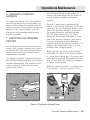
In-Filter Location Using a Float—The
float installation shown in Figure 2.3 keeps
probes from being submerged (or drying out),
and is economical to construct.
To construct a probe float, punch a hole
(slightly smaller than the probe diameter)
through a small piece of styrofoam. Be sure
the probes are no further than 6 inches
apart. Insert the probes into the float, as
shown in Figure 2.3.
OR
p
em
pH
T
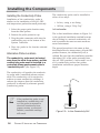
In-Line Location Using a Tee-Fitting—
Although in-line probe placement is a little
more difficult and requires some extra
plumbing, it has been found to be a very
accurate and safe way to place your probes.
In-line placement will give accurate readings
because water is moving across the probe tips
at all times, and because algae growth on the
probe tips is minimized.
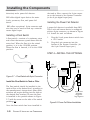
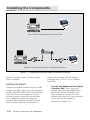
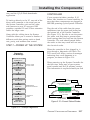
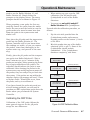
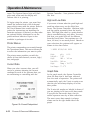
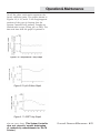
The probe is placed into a tee-fitting, as
shown in Figure 2.4. You will need to provide
the tee-fitting for this installation. The
diameter of the in-line portion of the tee
should be 1/2 inch (3/4” for conductivity
probe) regardless of whether you are using
laboratory or standard grade probes as they
are supplied from RK2. RK2 offers two
compression fittings for installation of the
probes. Flow rates across the pH and ORP
probes should be limited to < 10 GPM.
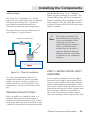
Be sure to install water shut-off valves, as
shown in Figure 2.6, to permit probe replacement. All fittings must be secured so there is no
water leakage.
It is important that the in-line probe extend
no more than about 50% into the flow
stream. If the probe protrudes too far into the
flow stream it will interrupt flow and interfere with the accuracy of the probe readings.
P
Probe
Shutoff
Valve
Compression
Fitting
Shutoff
Valve
Fig.2.4 • In-Line Location Using Tee Fitting
Figure 2.3 • In-Filter Location Using Float
CHAPTER 2: INSTALLING THE COMPONENTS
2-7