1
Online Operations, Quick Edit
2.
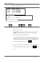
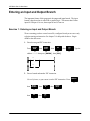
Monitor input data changes resulting from input device operation.
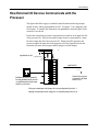
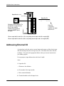
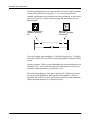
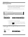
Press pushbutton 0. Note that the status bit goes from 0 to 1, as the instruction
goes from false to true. Now turn selector switch 6 to the on position. Note that
status bit I:2/2 goes from 0 to 1, as the instruction goes from false to true.
3.
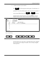
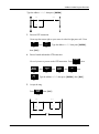
Access the output data file.
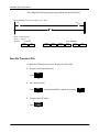
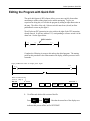
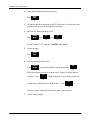
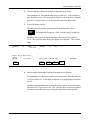
The output data file precedes the input data file in the data table. Press
CONFIG
OFFLINE
PREV
FILE
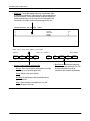
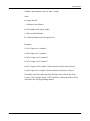
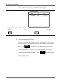
. The output data file appears. Since we didn’t specify a particular
CONFIG
F8
bit address, the cursor is located on the status bit having the lowest address,
O:3/0. This is also the status bit for pilot light 0 in our program. This is shown
below.
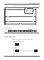
address
O:3
15
data
0
0000 0000
Press a key or enter value
O:3/0 =
REM RUN
no forces
address
15
binary data
data
0
decimal addr
PROC Addr 1
CHANGE
RADIX
SPECIFY
ADDRESS
FORCE
MONITOR
NEXT
FILE
PREV
FIILE
F1
F5
F6
F7
F8
4.
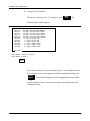
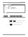
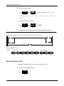
Monitor output data changes resulting from input device operation.
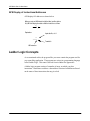
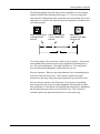
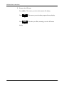
Press pushbutton 0 with selector switch 6 in the on position. Note that status bit
O:3/0 goes from 0 to 1, as the output instruction of our program goes from false
to true.
Continue to press pushbutton 0, as you turn selector switch 6 to the off position.
Note that bit O:3/0 goes from 1 to 0. This is because there is no longer a path of
true input instructions in the rung, causing the output instruction to go false.
4–11