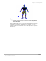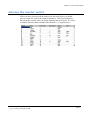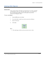
1
Digitiser USER MANUAL Table of Contents Chapter 1 - Introduction 1 Overview......................................................................................................................3 General information .....................................................................................................4 What’s new ..................................................................................................................5 Software installation ....................................................................................................6 Software registration ....................................................................................................7 Chapter 2 - The Stick Figure Builder 9 Overview......................................................................................................................9 Opening the Stick Figure Builder ..............................................................................10 Creating stick figures .................................................................................................11 Selecting the number of marker points ......................................................................12 Positioning marker points ..........................................................................................13 Making connections between marker points .............................................................15 Naming the marker points..........................................................................................17 Printing stick figures ..................................................................................................18 Saving stick figures....................................................................................................19 Capture image of stick figures ...................................................................................20 Chapter 3 - Digitising Data 21 Overview....................................................................................................................21 Create a new digitised data file ..................................................................................22 Digitising the data file................................................................................................23 On-screen information ...............................................................................................24 Obtaining co-ordinate data.........................................................................................25 Correcting mistakes in a digitised data file ................................................................26 Setting a scale ............................................................................................................27 Setting point colours ..................................................................................................28 Viewing the digitised data table.................................................................................29 Capture an image from the digitiser screen ...............................................................30 Printing digitised data ................................................................................................31 Saving digitised data ..................................................................................................32 Opening an existing digitised data file ......................................................................33 Chapter 4 – Video Capture 34 Overview....................................................................................................................34 Starting the video capture ..........................................................................................35 Setting up for video capture .......................................................................................36 Capturing videos ........................................................................................................38 Trim and/or recompress video ...................................................................................40 Chapter 5 - Collecting Quality Video Footage 42 Overview....................................................................................................................42 Video camera features ...............................................................................................43 Filming checklist........................................................................................................44 Page I Chapter 1 ‐ Introduction siliconcoach Digitiser is an interactive, movement analysis tool. Digitiser is designed for analysing the fundamentals of rigid body segment models, biomechanics, and 2D geometry at a higher level. siliconcoach Digitiser is just one of the software products in the siliconcoach range that provides video-based, motion analysis specifically designed for use in sports training, coaching, and biomechanical analysis. Page 1 Other siliconcoach video analysis products include: siliconcoach Pro Premier video-analysis software. siliconcoach Pro Server Server version of the premier videoanalysis software, siliconcoach Pro. siliconcoach timeWARP Instant video feedback. siliconcoach Student Cost effective, video-analysis software for teaching environments. siliconcoach Central Web-based database for centralization of data and reports. Technique Wizards Electronic check-list to guide and standardize discrete movement analysis. For more details on these or other siliconcoach products, visit www.siliconcoach.com . Page 2 Overview Introduction siliconCOACH – Digitiser provides you with the tools that let you retrieve point co-ordinate data from a windows movie file (*.AVI). This data can then be used to help you analyse the skill of interest. siliconCOACH – Digitiser is also ideal for teaching students the principles of 2D analysis. How it works First off, you’ll capture some video footage of your subject using the builtin capture facility. Then, you define an appropriate stick figure. Next, you digitise the co-ordinate data. The resulting data can be exported in the file format known as comma separated values (.csv). You’ll find that siliconCOACH Digitiser provides you with all the tools you need for gathering accurate co-ordinate data from the movement sequence. Topics This chapter contains the following sections: Section General information What’s new Software installation Software registration See Page 4 4 6 7 Page 3 Chapter 1 – Introducing you to siliconCOACH General information Licensing Unless you have a current site license, siliconCOACH - Digitiser can only be installed on a single machine. If you are unsure about your license arrangement, contact your local agent or siliconCOACH Ltd. Support Support is provided via fax, internet and email. Up to date contact information is available on the siliconCOACH website (www.siliconcoach.com) How to Use this Manual This manual is designed to give readers a quick understanding of how siliconCOACH - Digitiser is used and provide working examples to illustrate the many functions of the program. We recommend new users work through the examples in this manual prior to performing any analysis. Page 4 Chapter 1 – Introducing you to siliconCOACH What’s new Registration A web based registration system has been added. If direct access to the web is not available emailed registrations are now handled by an automated system. Integrated video capture • Added a TRIM AFTER CAPTURE preference that when activated, will always load the captured movie into the TRIMMER • Changed the layout of the CAMERA CONTROL buttons and modified the icons to prevent confusion. • Added a second user configurable combo box for naming movie files. • Added a CLOSE button to the form to simplify closing. • Added a TRIM button to the form. This button is only enabled when a movie file is selected in the FILE LIST. • Improved the resolution of the video capture preview. • The trimmed file can have the same name as the original. This will overwrite the original file. Note that this action cannot be undone. • The FORMAT setting of the DV video is now saved as a preference. • Update the Stick Figure character models • New ‘show trace’ feature allows users to see digitised stick figures animated over time. • All components feature a new refined user interface which groups common tasks together and simplifies work flow. • Interface design aligned with that used in siliconCOACH Pro 6. • An error reporting tool has been added. Trimmer General Page 5 Chapter 1 – Introducing you to siliconCOACH Software installation Installing the Digitiser Software The CD has an auto installer and should open automatically. If the auto installer does not open the program automatically, run ‘setup.exe’ from the CD, at which point you will be prompted to continue. Installing DirectX The SiliconCOACH installer provides a DirectX 8.1 installation option for your version of the windows operating system. If you are running Windows XP, you DO NOT need to install DirectX 8.1. Before installing SiliconCOACH, please make sure you install the version of DirectX that is appropriate for your operating system. When you install DirectX using the supplied installer, the following file and compression formats are installed by default. These formats will complement the existing multimedia file support already installed on your PC. Default File Formats: Motion Picture Experts Group (MPEG) Audio-Video Interleaved (AVI) QuickTime (version 2 and lower) WAV AIFF AU SND MIDI Default Supported Compression formats: MPEG Audio Layer-3 (MP3) (decompression only) Digital Video (DV) MPEG-1 MJPEG Indeo Cinepak Microsoft does not provide an MPEG-2 decoder. Several DirectShow-compatible hardware and software MPEG-2 decoders are available from third parties. For information on the availability of particular third-party codecs for redistribution with DirectShow applications, contact the codec manufacturer. Page 6 Chapter 1 – Introducing you to siliconCOACH Software registration Note You cannot use the software until you have registered it. The license file only activates the software on the computer you registered it for. If you change computers, reformat your hard drive or change your processor you will have to re-register. No personal information, other than hardware specifics of your computer and the contact details you enter, is transmitted to us. Registration Process The registration process is as follows and requires you to either be connected to the internet or have internet access in order to send and receive your registration: 1. When you first run the software you are presented with a registration wizard. 2. Select the Register option and click Next. 3. Enter the serial number you received with your siliconCOACH CD and click Next. 4. Fill out the contact details and click Next. 5. If you are connected to the internet then: a. Select the Web registration radio button b. Click Next c. siliconCOACH will attempt to connect to the registration server and register the software immediately d. If the web fails then: i. Click on the Back button ii. Select the Email registration radio button iii. Click Next iv. Click the Email Registration button v. siliconCOACH will attempt to send an email to the registration server and register the software vi. If this process is successful then you will receive an email reply. Go to step 7 If you are not connected to the internet or Step 5 has failed then: a. Select the Email registration radio button. b. Click Next c. Click the Save To File button. A Save File dialog box will open and prompt you to save the registration file. d. Save the file and then copy it to another PC that can connect to the 6. Page 7 Chapter 1 – Introducing you to siliconCOACH 7. 8. internet and send it to [email protected] e. If this process is successful then you will receive an email reply. Go to step 7. The email that you receive will include an attached text file you will need to: a. Double click the attachment file to open it. b. Choose SELECT ALL from the EDIT menu c. Choose COPY from the EDIT menu to copy all of the text. d. Open siliconCOACH and select Manually Enter License Key and then click Next. e. Right Click in the text box and choose paste. This will paste the contents of the attachment into this screen. f. Click FINISH. If you have any problems or issues please email [email protected] Page 8 Chapter 2 ‐ The Stick Figure Builder Overview Introduction In this section you will learn how to use the Stick Figure Builder to create, open, save and close stick figure files. Working with files in the Stick Figure Builder is very similar to working with documents in a word processor or spreadsheet application. What is a Stick Figure A stick figure is a model of a body defined by lines between points placed on significant body landmarks. The chosen figure defines the points you need to digitise for the movie you are analysing. A stick figure can include points for all the joints in the body or it can be just a limb or segment of interest. The greater the number of points in your stick figure, the longer it will take to digitise. In siliconCOACH Digitiser a stick figure can have a maximum of 30 points. Topics This chapter contains the following sections: Section Opening the Stick Figure Builder Creating Stick Figures Printing Stick Figures Saving Stick Figures Capturing Image of Stick Figure See Page 10 11 18 19 20 Page 9 Chapter 2 – The Stick Figure Builder Opening the Stick Figure Builder Overview Introduction The Stick Figure Builder screen provides you with the necessary capabilities to create the stick figure that you require. Opening the stick figure Complete the following steps to open the stick figure builder screen: 1. Open the siliconCOACH Digitiser software. 2. From the Tools menu select Stick Figure Builder. A new screen will appear. Page 10 Chapter 2 – The Stick Figure Builder Creating stick figures Overview Introduction A stick figure is used as the basis for the creation of a digitised data file. It can be as simple or complex as you require to gain the desired information. Topics This section contains the following topics: Topics Selecting the number of marker points Positioning marker points Making connections between marker points Naming the marker points See Page 12 13 15 17 Page 11 Chapter 2 – The Stick Figure Builder Selecting the number of marker points Introduction The first stage of creating a stick figure is to select the number of points that you require. To select the number of points Click on the Markers button. A number of sequentially numbered blue points will appear on screen in the top left of the stick figure layout panel. Numbers relating to the points will appear in column one of the table at the bottom of the screen. Page 12 Chapter 2 – The Stick Figure Builder Positioning marker points Select a model from the pictures on the right of the screen that most closely resembles the stick figure you wish to create. To make your selection click on the model. This picture will be relocated to the marker layout area. Using the posing model as a reference, position the markers on the anatomical points of interest. To position the markers: 1. Click and hold the left mouse button down. 1. Drag the marker to the desired position. 2. Release the mouse button. By default the Stick Figure builder is in ‘Move’ mode. If you have preformed another task such as ‘Connecting’ the markers and then want to go back and move a marker you will have to click the ‘Move’ button. Page 13 Chapter 2 – The Stick Figure Builder Note: For a cricket bowler, marker 1 may represent the ball and points 2 – 8 may represent anatomical landmarks. Page 14 Chapter 2 – The Stick Figure Builder Making connections between marker points Once all the markers have been positioned you make the connections between them by: 1. Selecting the colour of the line that will connect the markers. 2. Connect the markers by drawing lines between them. To select the colour of the line: 1. Select a colour from the colour palette. To connect two points: 1. Click on the Connect markers button. 2. Place the cursor on the first marker. 3. Click and drag until the cursor is positioned over the second marker. 4. Release the mouse. A line will be drawn between the two markers in the selected colour. The connection and colour of the line will be recorded in the table at the bottom of the screen. Page 15 Chapter 2 – The Stick Figure Builder Notes: ¾ A marker can accept multiple connections but can only generate TWO connections. When you digitise the point co-ordinate data a marker that does not accept or generate any connections will be drawn as a red square. You will generally use this sort of marker for a ball or other object that is separated from the body. Page 16 Chapter 2 – The Stick Figure Builder Naming the marker points When you have joined up all the markers for the stick figure you should type in a name for each of the numbered markers. This is not mandatory but will make it easier when you begin digitising the stick figure. It is easier to find the left knee than remember what marker 11 is supposed to be. Page 17 Chapter 2 – The Stick Figure Builder Printing stick figures Introduction Once you have made stick figures they are stored in a table within siliconCOACH Digitiser. You can print a stick figure in one of the following ways. Printing a stick figure from the table 1. From the file menu select Print. 2. Click Ok. To print a stick figure file (*.Sff): To allow you to import a stick figure file into another application and print from within that application: 1. Save the stick figure to a file. 2. Import the stick figure file into a word processor or spreadsheet application. 3. Print from within the application. Note: ¾ When importing a stick figure file into another application you should choose the appropriate settings for importing a comma separated values (CSV) file. Page 18 Chapter 2 – The Stick Figure Builder Saving stick figures Introduction Once you have made a stick figure you will want to save it into a location on the hard drive where you can easily find it again. It is a good idea to have one folder that contains all your stick figures located in the siliconCOACH Digitiser folder. To save a stick figure 1. From the File menu select Save. 2. Locate the folder in which you wish to store the stick figure. 3. Enter the filename. 4. Click Save. Note: ¾ The stick figure will be lost if you do not save it to a file. Page 19 Chapter 2 – The Stick Figure Builder Capture image of stick figures Introduction Once you have created a stick figure you may wish to save an image of the stick figure. Saving the stick figure image 1. Click on the Snapshot button. 2. Enter the name of the image. 3. Click Save. Note: ¾ The default folder for the images is C:\My Documents. Page 20 Chapter 3 ‐ Digitising Data Overview Introduction A digitised data file (.ddf) is a file that contains co-ordinate data about points that you have digitised. The co-ordinate data is measured in relation to the bottom left corner of the screen which is point (0,0). Also contained within the file is the stick figure that was used as a basis for the digitisation, the scale (if it was calculated), the path to the movie that was digitised and other relevant information. The path name of the movie is recorded in relation to its position to the .ddf file. If the need arises to move the files both the .ddf file and the movie files should be moved together. Gaining point co-ordinate data from a movie is a relatively straight forward process. Topics This chapter contains the following sections: Section Creating a new digitised data file Digitising the data file Obtaining co-ordinate data Printing digitised data Saving digitised data Opening an existing digitised data file See Page 22 23 25 31 32 33 Page 21 Chapter 3 – Digitising Data Create a new digitised data file 1. From the File menu select New. 2. Locate the folder which contains the movie you want to digitise (*.avi). 3. Select the movie and click Open. 4. Locate the folder which contains the stick figure you want to use (*.sff). 5. Select the stick figure file and click Open. Page 22 Chapter 3 – Digitising Data Digitising the data file Overview Introduction The process of using a stick figure as the basis for digitising a movie results in the production of a digitised data file. This file contains the co-ordinates of the digitised points and how they relate to the stick figure. Topics This section contains the following topics: Topics On-screen information Obtaining co-ordinate data Correcting mistakes in a digitised data file Setting a scale Setting point colours Viewing the digitised data table Capture image of digitiser screen See Page 24 25 26 27 28 29 30 Page 23 Chapter 3 – Digitising Data On-screen information Once you have opened a digitised data file, the movie and the following information will be visible on the screen: The movie controller: Used to navigate through the movie. Point out of bounds (frame): Click in this region if the specified point is not within the movie window. Out of bounds points are recorded as having co-ordinates of (-1, -1) in the Digitised Data File. Click on the [Point name]: Tells you the name of the point you should click on next, based on the stick figure that you are using. Two buttons for manual navigation through the points: The button on the left takes you back one point and the button on the right takes you forward one point. If you make a mistake you can use these buttons to move back or forward to the point you want to redo. If you go forward past the last point on the current frame of the movie you will be taken to the first point in the next frame. Current frame No: The frame number of the movies frame you are currently viewing. Total No frames: The total number of frames in the current movie. Page 24 Chapter 3 – Digitising Data Obtaining co-ordinate data 1. From the Preferences menu make a selection from the Digitise Every sub-menu. The default is to digitise every frame. 2. Use the movie controller to locate the frame you wish to begin digitising in. 3. Locate the first point in the movie and click on it. You will notice the name below the words Click on the change to the name of the second point. 4. If the point is not within the field of view then click on the Point out of frame button. 5. Once you have clicked on all the points in this frame the movie will advance the specified number of frames. 6. Repeat the process until you have reached the end of the movie or wish to stop. Note: You do not have to digitise all the frames in a movie: ¾ Use the movie controller to advance to the frame you wish to begin at. ¾ You can make a selection from the “Digitise Every” menu under “Preferences” menu. This will advance the movie the required number of frames as you finish digitising a frame. Page 25 Chapter 3 – Digitising Data Correcting mistakes in a digitised data file If you make a mistake while digitising a frame you can correct it by: 1. Using the movie controller at the base of the movie to locate the frame in the movie where the mistake was made. 2. Use the navigation buttons below the movie controller to go to the point on the frame that is incorrect. 3. Re-digitise the incorrect point. Page 26 Chapter 3 – Digitising Data Setting a scale Introduction siliconCOACH Digitiser allows you to calculate a scale for a movie so that you can use it as a reference for subsequent calculations of distance, speed etc. To set a scale To do this you need to know the length of some object in the movie. 1. Choose the units to use as a basis of the scale by selecting either meters or feet from the Scale Units option on the Scale menu (The default unit is meters). 2. Select Set Scale from the Scale menu. 3. Click on two points in the movie that are a known distance apart and then enter that distance. After you have done this the scale will appear in the status bar at the bottom of the screen. Page 27 Chapter 3 – Digitising Data Setting point colours Under the Preferences menu you have the option of changing the colours that are used to display the points as you digitise the stick figure. There are three situations that you can set the point colour for. 1. Firstly there is the default point colour, this colour is used to display the points unless they are the currently selected point or a redigitised point. 2. Secondly there is the colour of the currently selected point. This is only visible when you are navigating through points that have already been digitised. 3. Thirdly there is the colour used to display points that have been redigitised. You can choose to use these colours only on your current file or on all subsequent files. Page 28 Chapter 3 – Digitising Data Viewing the digitised data table Click on the Show Data icon. The table will open and will fill the screen. The table contains information about the stick figure and movie that you are using along with the x,y coordinates of the points that you have digitised. Page 29 Chapter 3 – Digitising Data Capture an image from the digitiser screen When you are digitising the point co-ordinate data you may wish to save an image from the digitiser screen. Saving an image from the digitiser screen 1. Click on the Save image button. 2. Enter the name of the image. 3. Click Save. Note: ¾ The default folder for the images is C:\My Documents. Page 30 Chapter 3 – Digitising Data Printing digitised data Introduction Once you have digitised a stick figure the data is stored in a table within siliconCOACH Digitiser. You can print the data in one of the following ways. Printing digitised data from the table 1. From the File menu select Print. 2. Click Ok. Printing a digitised data file (*.Ddf) To allow you to import a digitised data file into another application and print from within that application: 1. Save the digitised data to a file. 2. Import the digitised data file into a word processor or spreadsheet application. 3. Print from within the application. Note: ¾ When importing a digitised data file into another application you should choose the appropriate settings for importing a comma separated values (CSV) file. Page 31 Chapter 3 – Digitising Data Saving digitised data Introduction Once you have digitised a stick figure the data is stored in a table within siliconCOACH Digitiser. You will want to save it into a location on the hard drive where you can easily find it again. It is a good idea to have one folder that contains all your data files located in the siliconCOACH Digitiser folder. To save a digitised file 1. From the File menu select Save. 2. Locate the folder in which you wish to store the data file. 3. Enter the filename. 4. Click Save. Note: ¾ The data will be lost if you do not save it to file. Page 32 Chapter 3 – Digitising Data Opening an existing digitised data file Introduction You can open a digitised data file if you want to make corrections or continue the digitising. To open an existing digitised data file 1. From the File menu, in the Digitiser Screen, select Open. 2. Locate then open an existing digitised data file (*.ddf). The movie that relates to the file will also open. 3. Click on the open table icon and view the table to determine the last frame that was digitised. 4. Close the table. Page 33 Chapter 4 – Video Capture Overview Introduction Each capture card comes with its own interface and the standard of these interfaces varies in quality. siliconCOACH – Digitiser has a program to simplify the capture process. This section describes the Video Capture process. Topics This chapter contains the following sections: Topic See Page Starting the Video Capture 35 Setting up for Video Capture 36 Capturing Videos 38 Trim/Recompress the Movies 40 Page 34 Chapter 4 – Video Capture Starting the video capture Introduction The Capture Screen is where movie files are captured and saved. Buttons The following buttons on the Capture Screen: Buttons Start button Stop button Camera control File name Directory and File lists Description To Start capture. To Stop capture. Allow you to play, stop, forward and rewind in the camera control. Let you name your file with date, name and autoincrement number. Allow you to manage your file and provide right click features. Page 35 Chapter 4 – Video Capture Setting up for video capture Introduction The Settings Screen provides you with instructions for setting up your video capture and ensuring it is properly configured. The Settings Screen To open the Settings Screen click on the Settings tab at the left of the Capture Screen. The Settings Screen will appear as follows: continued on next page Page 36 Chapter 4 – Video Capture Configurations The following configurations are on the Settings tab, in almost all cases sensible defaults have been chosen for you and you do not need to make any changes: Configurations Video Size Sub Type Frame rate Apply Analogue Video Standard Audio Format Capture Audio Mute Device Settings Description Automatically detect the video camera source that you are using. Set the Size of the video. Note, for some video sources, you cannot specify the size. Sub type of the Video device. Note, for some video sources, you cannot specify the subtype. The frame rate would set on default. Note, for some video sources, you cannot specify the frame rate. Apply the changes to the frame rate. Select the correct standard for your video source from the drop down menu. It's only available when you use analog video camera. Select the audio device. You may set the audio format to default or you can choose the format in the drop down list. Select the tick box to capture the audio. Select the Mute tick box to mute audio while you are working on the Capture screen. Provides access to manufacturer specific configuration dialogs Note The settings made available to you are dependent on the type of card you have. Each manufacturer provides a settings dialog with their own layout and features, but we will only deal with those settings that are necessary for setting up your card for basic capture. Please refer to the documentation that comes with your card for further information about the settings and dialogs provided by your cards manufacturer. Some options may be greyed out and unavailable depending on the type of video card you have. In these cases the manufacturer or operating system will automatically have selected a default setting which you have to use. Page 37 Chapter 4 – Video Capture Capturing videos How to capture videos 1. Connect your camera to your PC and turn the camera on. 2. Click on the Video Capture button in the Function Tab to open the Capture Screen. 3. In the File name section, type in a name for the movie clip that you are about to capture. We provide three convenient ways to let you name your movies; these are by Date, Name and Auto-increment numbers. 4. Use the Directory and Folder list to specify the folder where you want to save the file. 5. If you want to create a new folder you can: Right click the folder list. Create a folder by selecting New Folder from the right click menu. Name the folder. Return to the Capture Screen. 6. If you are using an analogue camera, start playing the tape and click on the Start button to start the capture. If you are capturing via Firewire (IEEE 1394), clicking on the Start button will automatically play the camera. 7. Click on the Stop button when you have captured the desired movie sequence. Page 38 Chapter 4 – Video Capture Movie size As movies are large in size – about 1.5 to 4.0 MB per second, you should only capture from a short time before the event of interest to just after the event of interest. This will help conserve disk space. Exiting the Capture screen To exit the Capture Screen click on the exit button at the bottom right of the screen. This will take you back to the Presentation Builder screen. Page 39 Chapter 4 – Video Capture Trim and/or recompress video Introduction The Trimmer allows you to trim and/or recompress the video that you have just captured or existing movies. It also provides you some compression options. Trimming a movie 1. Click on the movie file from the file list in the Capture Screen, this will highlight the movie. 2. Click the Trim button. 3. In the Source section it will display the file path of the selected movie file. 4. Double click on the Set Destination button to bring up the save dialogue and select the directory where you like the file to be saved and the filename. 5. Select a suitable compression option. 6. Move the slider to view the beginning point where you want to trim from, and click In. 7. Move the slider again to view the end point where you want to trim to, and press Out. Page 40 Chapter 4 – Video Capture Note: You can use the mouse to slide the arrow on the bar or shift it with the arrow keys on the keyboard to the point that you want the movie to start or finish. The numbers under the slider are the frame numbers of the In point, current point and Out point. 8. Then Press Trim in the Compress section to Trim and/or Recompress the movie according to the settings you have made. 9. After the compression finishes, a dialog will pop up and provide you with the option to view the file in the Media Player. Click Yes to view it or click No to exit. Page 41 Chapter 5 ‐ Collecting Quality Video Footage Overview Introduction If a picture is worth a thousand words how much is a video worth? If you are going to videotape an athlete so that you can help them improve their performance it is important that you get the highest quality video available. Topics This chapter contains the following sections: Section Video Camera Features Filming Checklist See Page 43 44 Page 42 Chapter 5 – Collecting Quality Video Footage Video camera features Overview Introduction You do not necessarily have to buy expensive equipment, but you need to use what you have to your best advantage. To do this you need to have a general idea about what features on your video camera are important. The items listed in this section are the main features of a video camera, which are of specific interest in video taping for Digitiser analysis. Focus controls Most cameras have an auto focus capability. This means the camera will automatically focus itself. In many sporting set-ups it is recommended that you use the manual focus because it prevents the camera focusing on an unwanted object in the background or foreground as the subject moves. As a rule of thumb, use the manual focus whenever possible. Shutter settings The shutter controls the period of time that the videotape is exposed to the image. If the image is moving at high speeds, then a low shutter speed (1/120) will result in a blurred image, whereas a high shutter speed (1/1000) will result in a clear picture. The shutter speeds on a video camera can be manually controlled depending on the activity being videotaped. On many cameras you select a picture that represents a shutter speed, for example, an icon of a runner or a golfer (in the case of Sony cameras). As the shutter speed increases, less light is allowed to reach the videotape, causing the image to become darker. Therefore, you need to ensure that you have good lighting if you intend to video at high shutter speeds. Note: ¾ These settings are required for digital video cameras as well. Page 43 Chapter 5 – Collecting Quality Video Footage Filming checklist Before filming Check the following: From which angle will the event/s of interest be best captured? Remember that the plane of movement will need to be perpendicular to the camera if you intend to make measurements from the movie. Is the sun or light going to cast shadows on the event being captured? Lighting should be from behind the camera side towards the event. Will the lighting cause reflections that will affect the image being captured? This includes reflections off walls or water as well as off the object/person being videotaped. Is the camera positioned on a tripod to reduce vibrations? Will the whole event be captured without panning the camera? Panning introduces errors that will make any measurements of speed or distance over a time period inaccurate. Is the camera positioned at right angles to the plane in which the event takes place? If not errors due to perspective will be created. Is the person being videotaped wearing clothing that will obscure their actions or limb end point positions? This may be floppy tops, long baggy shorts, skirts or long hair which could be plaited, tied up or taped down. Page 44 Chapter 5 – Collecting Quality Video Footage During filming Check the following: Using a Scale, either: ¾ Put makers in the field of view that are a known distance apart; or ¾ Hold an object of known length at the position where the event will occur, first horizontally then vertically for 20 seconds in each position. This could be a 1-metre length of wood. It is on this linear scale that all calculations of distance and speed are based. If you use this method to record a scale and any adjustments are made to the cameras field of view during videotaping the scaling rod must be shown in the new field of view. As the people/objects being videotaped change, a chalkboard or piece of paper with the name of the new person/object should be displayed in front of the camera. This allows someone who is unfamiliar with the people/objects to identify them. If filming multiple trials of a subject, be sure to indicate the trial number by showing numbered pieces of paper or having the subject hold up the proper number of fingers. Complete a filming record that includes all relevant information. This information may include the persons: ¾ Name ¾ Standing height ¾ Reach height ¾ Weight ¾ Age ¾ Skill level ¾ Type of equipment used ¾ Any other information that may be of use at a later date. Page 45