1
8 Pre-Processing with the
graphical editor: DIGEDIT
.....
Chapter 8: Pre-processing with the graphical editor: DigEdit
8.1 Introduction..........................................................................................................................................8-3
8.2 Concepts and terms.............................................................................................................................8-3
8.3 General settings...................................................................................................................................8-5
8.3.1 Ids and values..............................................................................................................................8-5
8.3.2 Snap Options...............................................................................................................................8-6
8.3.3 Label............................................................................................................................................8-6
8.3.4 Show............................................................................................................................................8-6
8.4 Menu bar..............................................................................................................................................8-6
8.5 Toolbar...............................................................................................................................................8-11
8.6 How to …...........................................................................................................................................8-12
8.6.1 How to create a new map..........................................................................................................8-12
8.6.2 How to open an existing map.....................................................................................................8-12
8.6.3 How to import a shape file (*.shp)..............................................................................................8-12
8.6.4 How to export a shape file (*.shp)..............................................................................................8-12
8.6.5 How to merge multiple map files................................................................................................8-13
8.6.6 How to add a point.....................................................................................................................8-13
8.6.7 How to add a line.......................................................................................................................8-13
8.6.8 How to add a polygon................................................................................................................8-14
8.6.9 How to add a linked point...........................................................................................................8-14
8.6.10 How to select data objects.......................................................................................................8-14
8.6.11 How to delete data objects.......................................................................................................8-15
8.6.12 How to change a point object...................................................................................................8-15
8.6.13 How to change a line object.....................................................................................................8-15
8.6.14 How to change a polygon object..............................................................................................8-17
8.6.15 How to change a linked point object........................................................................................8-18
8.7 Using digitising equipment.................................................................................................................8-19
Royal Haskoning
Triwaco User's Manual
8.1 Introduction
DigEdit is a Windows-based graphical editing tool, which can be used to create and edit maps (coordinates
as well as associated parameters). DigEdit can handle input from keyboard, mouse and digitiser. Graphical
editing, however, is only possible using either a mouse or a digitiser. Menu commands can be issued using a
keyboard and/or a mouse.
The program facilitates the process of modelling, especially the generation of the grid and parameter input.
DigEdit can be called from within the TriShell, but can also be used stand-alone.
DigEdit stores the digitised or edited information in ASCII text files that can be read by the internal and external
Triwaco programs and by GIS based programs like ArcView, ArcGIS and ArcInfo. Editing of maps is usually
realised using a mouse, changes being displayed instantaneously on screen, the results may be printed.
8.2 Concepts and terms
DigEdit can be started as a stand-alone program by selecting the DigEdit-icon from the Triwaco programs
folder. However it is usually started from Triwaco data sets by highlighting a parameter and subsequently
choosing 'Parameter' 'View' 'Map' from the pull-down menu, or right-click mouse choosing 'Edit Map file'
(Initial data set) or 'View Map file' (other data set) or just by double clicking the highlighted parameter.
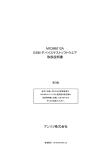
DigEdit will start and open the map, which corresponds with the parameter selected. If no map exists the
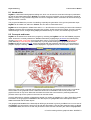
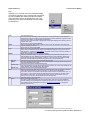
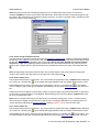
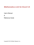
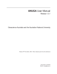
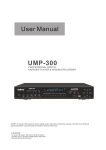
program displays a warning. The map will be displayed in a graphical screen, an example is shown below.
At the top of the screen a menubar and a toolbar present the user the possibility to issue many commands.
At the bottom of the graphical screen a status bar shows the coordinates of the mouse pointer in the
graphical screen in map units. Moreover the status bar shows the actual mode for presenting labels and
presents some help for the options in the menu bar and the toolbar.
A map is defined as a collection of dataobjects stored in a number of readable (ASCII) files. These files contain
information on the geographical location of the data objects; the properties of the data objects and the
name associated with the data objects.
The geographical location of the data objects defining a parameter is given by an ID and one or more sets of
coordinates, this information is stored in a file with the parameter's name and the extension 'ung'. An ID and
a parameter value, stored in a file with the parameter's name and the extension 'par', define the properties
8 Pre-Processing with the graphical editor: DIGEDIT-3
Royal Haskoning
Triwaco User's Manual
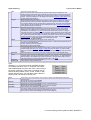
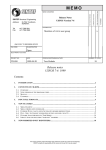
of the parameter. Finally, the names associated with the data objects are given by an ID and a text string
and stored similarly in a file with extension 'nam'. An example of a file with point data is given below. The files
are always space delimited. Tab delimited will result in errors by the various programs.
DigEdit recognizes the following data objects:
data object
point
line
polygon
linked point
vertex
Definition
Each point is defined by a unique ID and a single set of coordinates.
A point may be assigned a value and a name. The coordinates, value and name are stored in
separate files: (point.ung, point.par and point.nam)
A line is defined by a unique ID and a series of two or more vertices.
The coordinates of all vertices are different. A line may be assigned a value and a name. The
coordinates, value and name are stored in separate files: (line.ung, line.par and line.nam)
A polygon is defined by a unique ID and a series of vertices; the number of vertices generally
will be four or more. The coordinates of the first and last vertex should be identical. A polygon
may be assigned a value and a name. The coordinates, value and name are stored in
separate files: (polygon.ung, polygon.par and polygon.nam)
A linked point is defined by a single set of coordinates. The point is linked to either a line or a
polygon with a specific ID; the point's ID should be equal to the object's ID it is linked to. A
linked point should be assigned a value. Both the coordinates and the value are stored in the
same file: linked.ung
A vertex is defined by a single set of coordinates. No vertex can exist by itself, but always is
part of a line or a polygon. A vertex never is assigned a value or a name. The vertex's
coordinates are stored in the ung-file of the line or polygon it belongs to.
Depending on the way DigEdit is started some of the types of data objects may be enabled or disabled at
start-up. If DigEdit is started as a stand-alone program all types of data objects are available. However, if
DigEdit is called from the TriShell, some of the data objects may be disabled. The toolbar-icons of disabled
data objects will be displayed in gray. This may be the case opening the map of, for example, the grid's
boundary. In that case it is not possible to add a line or a point to the map, because the grid's boundary
consists of a polygon only. Selecting a point (or vertex), however, still will be possible.
An existing map can be used as background map; e.g. the data objects are displayed on the screen while
one is editing another map. The background map, however, cannot be edited. Apart from DigEdit's ung-files
some other file types, containing graphical information, may be used as background map. In order to display
the background map in real world coordinates, pixel oriented background maps should be accompanied by
an associated so-called world-file. At present DigEdit supports the following background file types:
AutoCAD DXF files
ARC/INFO ungenerate files
ArcView Shapefiles
Dawaco maps
Windows Bitmap files
TIFF files
GIF files
PCX files
JPEG files
*.dxf
*.ung
*.shp
*.map; *.top
*.bmp
*.tif
*.gif
*.pcx
*.jpg
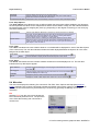
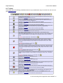
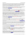
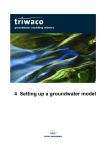
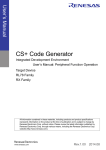
While opening a bitmap as a background, DigEdit will display a dialog box, which can be used to scale the
bitmap to the edited map. The size of the pixels can be changed as well as the origin of the bitmap (the upper
left corner). Changing the width or the height independently from one another may result in a distorted
bitmap. By pressing the Save button, DigEdit will save a world-file (bitmap.tfw) with the actual values for pixel
size, origin and rotation shown in the dialog box. The next time DigEdit opens the bitmap (for example
bitmap.bmp) the values stored in the associated world file will be given as default values. If no world file is
present the width and height of the pixels are computed from the width and height of the area displayed in the
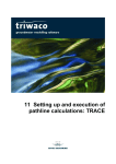
bitmap (in user units) and the number of pixels in horizontal and vertical direction. The world-file may also be
edited or created using a text-editor. It is important that the worldfile (*.tfw) has the same name as the bitmap
file. Below an example of a dialog box and next to it the same data shown in the tfw-file.
8 Pre-Processing with the graphical editor: DIGEDIT-4
Royal Haskoning
Triwaco User's Manual
It is possible to open several background maps at the same time to facilitate editing of the current map.
8.3 General settings
The general settings, which are stored in the options section of the Setting File DigEdit.ini, can be accessed
via the 'Options' | “Setup' command. This command will open the options window.
The options window contains four specific areas:
1. the Ids and Values area
2. the Snap Options area
3. the Label area
4. the Show area
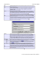
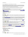
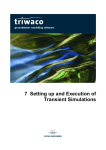
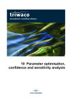
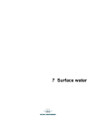
8.3.1 Ids and values
The 'Ids and Values' area allows the user to define default values for the ID, the increment and for the
conversion of new data object's ID to a value. Moreover, the user can specify whether or not the program
displays the pop-up dialog box for defining ID, value and name of the data objects every time a data object is
added to the map.
8 Pre-Processing with the graphical editor: DIGEDIT-5
Royal Haskoning
Default ID
Increment
Conversion ID to value
Triwaco User's Manual
Set the default value for the ID of new data objects
Set the increment for the ID of new data objects. Every time a data object is
added its ID will be increased with this number.
Multiplication factor to automatically compute a value for every data object added.
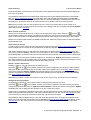
8.3.2 Snap Options
The 'Snap options' area allows the user to define whether the snap option will be enabled or not. Moreover,
the user specifies the values for the snap distance and the search radius. Finally, the user indicates whether
the measurement units for snapping are pixels (e.g. depending on the degree of zooming) or user units (e.g.
'real world' measures).
Snap Distance
Search radius
Set the snap distance. Whenever a new point (or vertex) is closer to an existing
point than the snap distance the new point will be moved to the exact location of
the existing point. The snap distance has no effect on existing data objects,
unless they are moved or snapped to a new position.
Set the search radius. In selecting an existing data object the search radius
defines the area in which the program searches for the desired data object. The
larger the search radius the less accurate one has to point (with the mouse) to a
data object in order to select it.
8.3.3 Label
The 'Label' area allows the user to define whether or not labels will be displayed for each of the data objects
of the current map. The user also indicates whether the label displayed defines the object's ID or the value
assigned to the data object.
Hide Labels
IDs
Values
Do not display the data object's labels if the check box in front is activated (
Choose whether to display the Ids of the data objects or their values.
).
8.3.4 Show
The 'Show' area allows the user to define whether certain items will be displayed or not. The user also
indicates the way data objects appear.
Show Vertices
Display all vertices belonging to a line or polygon if the check box in front is
activated (
).
Fill Polygons
Fills the polygon (with a solid color fill) if the check box in front is activated (
Otherwise displays the outline only.
Tic Marks
Display the (four) tic marks if the check box in front is activated (
Names
Display the names of data objects if the check box in front is activated (
).
).
).
8.4 Menu bar
The menu bar displays the following five commands: File, Edit, View, Options and Help (See graphical
screen). Selecting one of these commands activates a pull-down menu with a number of sub-commands.
Some of the sub-commands may be activated by a shortcut-key (generally the Ctrl-key and another
character).
File
Selecting 'File' from the menu bar activates the
File Commands pull-down menu. The pull-down
menu offers the following sub-commands to
choose from:
8 Pre-Processing with the graphical editor: DIGEDIT-6
Royal Haskoning
New
Open
Append
Triwaco User's Manual
Create a new map. Issuing this command causes the program to close the current map and
start with a blank screen.
Open an existing map. Issuing this command causes the program to prompt for a filename
(usually with extension ung).
The file selected will be opened and the program checks whether the corresponding
parameter file (par file) is present. Next to ung files, DigEdit can open ArcView
shapefiles (*.shp).
Shortcut-key for this command: Ctrl+O.
Append an existing map to the current map. All properties of the data in the new map
(coordinates as well as ID's and values) will be appended to the current map. Next to ung
files, DigEdit can append ArcView shapefiles (*.shp). After appending data one should
be very careful with saving the map. Use the correct name for the *.ung file and the *.par file
and be sure to activate the check box in front of the parameter file (
).
NOTE that appending data objects with the same ID's as data objects in the actual map will
change their values to the values of the data objects in the map that is being appended.
Save the current map, using the name in the title bar. If no name is present the 'Save As'
command will be executed.
Issuing this command will result in the popup of a dialog box by which the user is prompted
for saving the map file, the parameter file and name file. The names for these files should
only differ by their extension (respectively ung, par and nam). It is recommended to activate
Save
at least the check boxes in front of the map file and the parameter file (
Shortcut-key for this command: Ctrl+S.
Save As
Background
Open
Append
Close
Print
Exit
).
Save the current map as a DigEdit map file or as an ArcView shape file (*.shp). The
program will prompt the user to give a name. While saving the current map as a DigEdit
map, it is strongly recommended to use the default extensions for the associated files: 'ung'
for the map file, 'par' for the parameter file and 'nam' for the file with data object names.
Note that saving a map with overlapping polygons as an ArcView shape may result in an
erroneous shapefile. DigEdit and Triplot may properly read these files, while within ArcView
unexpected polygons may be present. This problem can be avoided by directly importing
*.ung files in ArcView using a specific ArcView extension made by Royal Haskoning.
Open an existing map to be displayed as background for the current map. Standard DigEdit
files may be used as well as several other file types as a background.
Append a background map to the background. The current background map(s) and the map
to be appended will be displayed. Standard DigEdit files may be used as well as several
other file types as a background.
Close all background maps and display the current map with a blank background.
Send the actual view of the map (the part that is displayed in the window) to the printer. All
visible data objects in the actual view, including any background map will be printed. The
printer settings can be adjusted. The user may choose to automatically scale the actual view
to the size of the paper or to enter a fixed scale. Shortcut-key for this command: Ctrl+P.
Close the current map and quit the program. Issuing this command, while the current map is
not saved to disk will cause the program to display a warning and to ask whether or not to
save the current map.
NOTE that canceling the Exit command is not possible.
8 Pre-Processing with the graphical editor: DIGEDIT-7
Royal Haskoning
Triwaco User's Manual
Edit
Selecting 'Edit' from the menu bar activates the Edit
Commands pull-down menu. Several sub-commands
are only available after editing actually has started.
The inactivated choices are displayed in gray. The
pull-down menu offers the following sub-commands
to choose from:
Undo
Delete
Snap
Modify
IDs and
Values
Values only
Names only
Table
Add
Point
Cancel the last action.
The last action will be added to the command: e.g. the command will be 'Undo Add Point'
when the last action was adding a point. Issuing this command causes the program to erase
the last action: adding, moving or editing a data object.
Every time the 'Undo' command is being issued the program displays the preceding action in
the pull-down menu.
Shortcut-key for this command: Ctrl+U.
Remove the selected data object(s) from the current map. All information associated with
the data object(s) will be lost.
Shortcut-key for this command: Del.
Move one or many selected points, vertices or linked points to the location of a not selected
point, vertex or linked point in the vicinity. If the selected point(s) are very close to any not
selected point, i.e. within the snap distance, the points will be moved to the exact location of
the existing not selected point.
Modify the properties of the selected data object(s).
Using the command 'Modify' it is possible to change the ID's, values and names for all
selected objects at once. Modifying a selected data object is also possible by selecting an
object with the right-hand mouse button. However, in this case it is not possible to modify
more than one data object at the same time (unless they have the same ID’s).
Change both ID's and values of the selected data object(s).
Note that changing ID's will cause all of the selected objects having the same ID and hence
the same value and name as well.
Change the value of the selected data object(s).
It is recommended to use this option rather than the previous one. In this case values can be
easily restored, without affecting other data objects.
Change the name of the selected data object(s).
Edit the parameter file ('par' file) belonging to the current map. It is only possible to edit the
values of the data objects (2nd column). The ID’s (1st column) cannot be edited).
Note that it seems to be possible to edit the first column and even to delete entire rows, e.g.
data objects. Closing and reopening the table will restore the changes for the first column.
Note that this option does not work for linked points, because the parameter value of a
linked point is not stored in the parameter file but in the map file!
Add data objects to the current map.
Add a point to the current map.
The point is added pressing the left-hand mouse button. Every time a point is added the
program displays a pop-up dialog box and prompts to enter an ID, a value and name. The
pop-up dialog box is not displayed if the option ‘prompt for id and values’ in the general
settings is switched off.
8 Pre-Processing with the graphical editor: DIGEDIT-8
Royal Haskoning
Line
Polygon
Linked point
Vertex
Select
Select Ids
Lasso
Select All
Unselect All
Triwaco User's Manual
Add a line to the current map.
Every time the left-hand mouse button is pressed a vertex (point) is added to the line.
Pressing the right-hand mouse button adds the last vertex (point) to the line and causes the
program to display the pop-up dialog box for entering the ID, value and name associated to
the line. The pop-up dialog box is not displayed if the option ‘prompt for id and values’ in the
general settings is switched off.
Add a polygon to the current map.
Every time the left-hand mouse button is pressed a vertex (point) is added to the polygon.
Pressing the right-hand mouse button adds the last vertex (point) and closes the polygon.
The program displays the pop-up dialog box for entering the ID, value and name associated
to the polygon. The pop-up dialog box is not displayed the option ‘prompt for id and values’
in the general settings is switched off.
Add a linked point to the current map.
Every time the left-hand mouse button is pressed a linked point is added. The program
displays the pop-up dialog box for entering the Link-ID, the ID and the value and name
associated to the linked point. The Link ID entered should be the ID of the line or polygon
the linked point refers to. Selecting this line or polygon prior to assigning the linked point will
cause the program to automatically enter the ID of the selected line or polygon in the dialog
box. The ID of the linked point itself is created by the program and can only be used in order
to select the point by its ID. It is strongly recommended not to switch off the option ‘prompt
for id and values’ in the general settings while adding linked points.
No shortcut-key for this command
Add a vertex to an existing line or polygon in the current map.
The vertex is added pressing the left-hand mouse button. In order to add a vertex the line or
polygon has to be selected first.
No pop-up dialog box will be displayed.
Shortcut-key for this command: Ins.
Select data objects from the current map.
To select single items one should enter 'Select mode' by choosing the select-icon and one of
the data object types (point, line, polygon, linked point) from the toolbar. To select multiple
items one at a time it is possible to use the left mouse-hand button together with the Controlbutton.
Select data objects of a chosen type of which the ID's are within a user-specified range.
Using this option will select all data objects of a chosen type that are situated (partly) within
a polygon (lasso). The polygon should be entered as a normal polygon, i.e. stop entering the
lasso by adding a point with the right-hand mouse button. The type of data object must be
selected in advance by selecting the appropriate button in the toolbar
Select all data objects of the current map.
Undo selection of all (selected) items.
View
Selecting 'View' from the menu bar activates the View
Commands pull-down menu. It comprises commands
that enable adjustment of the size of the current map on
the screen (zooming). These View commands can be
issued via this pull down menu, via the Toolbar or with
specific Shortcut-keys. The pull-down menu offers the
following sub-commands to choose from:
Reset
Zoom In
Zoom Out
Zoom Box
Fit the map in the current window, thus giving an overview of all data objects belonging to
the actual map.
Shortcut-key for this command: Home.
Enlarge the scale with a fixed amount.
Shortcut-key for this command: Gray + (on the numerical keypad).
Reduce the scale with a fixed amount.
Shortcut-key for this command: Gray - (on the numerical keypad).
Define the area to be displayed by drawing a box.
The area is defined by keeping the left-hand mouse button pressed and moving the cursor
from the left-hand top corner to the right-hand bottom of the box.
Shortcut-key for this command: Gray * (on the numerical keypad).
8 Pre-Processing with the graphical editor: DIGEDIT-9
Royal Haskoning
Triwaco User's Manual
Options
Selecting 'Options' from the menu bar activates the
Options Commands pull-down menu. It comprises
commands that define overall parameters for the
DigEdit session. The pull-down menu offers the
following sub-commands to choose from:
Setup
Colors
digitiser
Tics
Bitmap
Label Polygons
The user can set own preferences within DigEdit. These preferences are referred to as the
general settings.
The colors used to display different types of data objects may be redefined here. The default
colors used by DigEdit are:
Points
Light-green
Lines
blue
Polygons
Dark-green
Vertices of lines and/or polygons
purple
Linked points
blue
Selected data objects
red
Define the digitizing equipment used and the settings for the communication between the
computer and the digitizing equipment. One can only choose from a restricted number of
digitisers.
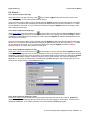
Define the coordinates of the tic points. If the user does not define the tics through the
window shown below, the tics are derived from the amount of pixels at the actual screen.
Typical amounts of pixels for normal screens are nowadays 800 by 600 or 1024 by 800. If no
digitiser is attached the left-hand side of the window is not available. The user can only
change the coordinates of the map (at the right-hand side). This may be used to position the
screen if no map is opened yet. Changing the map's orientation is not possible; as long as
no digitiser is attached the maps within DigEdit are oriented to the north!
Define or change the way bitmaps are used as a background. If more than one bitmap is
present as a background only the last one appended can be changed.
The background bitmap dialog box will be displayed.
Write the polygon labels at the center of each polygon.
Help
Selecting 'Help' from the menu bar activates the Help
Commands pull-down menu. The pull-down menu offers
the following sub-commands to choose from:
Help
About DigEdit
About Royal Haskoning
Start this DigEdit Help file, using the installed HTML-browser.
A pop-up window, showing the current version of DigEdit
A pop-up window, showing general information on Royal Haskoning
8 Pre-Processing with the graphical editor: DIGEDIT-10
Royal Haskoning
Triwaco User's Manual
8.5 Toolbar
The toolbar offers the following possibilities that also may be addressed using commands from the menu bar
(See graphical screen).
Create a new map. Issuing this command causes the program to close the current map
and start with a blank screen.
Equivalent to 'File' 'New' from the menu bar.
Open an existing map. Issuing this command causes the program to prompt for a
filename (usually with extension ung). The program will open the selected file and looks
for the corresponding parameter file (par file).
Equivalent to 'File' 'Open' from the menu bar; Shortcut-key: Ctrl+O.
Save the current map, using the name in the title bar. If no name is present the user is
prompted for one.
Equivalent to 'File' 'Save' from the menu bar; Shortcut-key: Ctrl+S.
Send the actual view (the part that is displayed in the window) to the printing-device. The
view includes all data objects visible with the actual state of zooming and any
backgrounds selected.
Equivalent to 'File' 'Print' from the menu bar; Shortcut-key: Ctrl+P.
Cancel the last action.
Equivalent to 'Edit' 'Undo' from the menu bar; Shortcut-key: Ctrl+Z.
Select one or more data objects from the current map.
THE SELECT-ICON IS USED IN ASSOCIATION WITH A DATA OBJECT ICON.
Add a point to the current map.
The point is added pressing the left-hand mouse button. Every time a point is added to the
map the program displays a pop-up dialog box and prompts to enter an ID, a value and
name.
To select a point use this icon in association with
Add a line to the current map.
The line's vertices are added pressing the left-hand mouse button, except for the last
vertex that is added pressing the right-hand mouse button. Every time a line is added to
the map the program displays a pop-up dialog box and prompts to enter an ID, a value
and name.
To select a line use this icon in association
Add a polygon to the current map.
The polygon's vertices are added pressing the left-hand mouse button, except for the last
vertex that is added pressing the right-hand mouse button. Every time a polygon is added
to the map the program displays a pop-up dialog box and prompts to enter an ID, a value
and name.
To select a polygon use this icon in association with
Add a linked point to the current map.
The linked point is added pressing the left-hand mouse button. Every time a linked point is
added the program displays a pop-up dialog box and prompts to enter an ID, a value and
name.
To select a linked point use this icon in association with
Enlarge the scale with a fixed amount.
Equivalent to 'View' 'Zoom In' from the menu bar;
Shortcut-key: Gray +
Reduce the scale with a fixed amount.
Equivalent to 'View' 'Zoom Out' from the menu bar;
Shortcut-key: Gray Define the area to be displayed by drawing a box.
The area is defined by keeping the left-hand mouse button pressed and moving the cursor
from the left-hand top corner to the right-hand bottom of the box.
Equivalent to 'View' 'Zoom Box' from the menu bar;
Shortcut-key: Gray *
Fit the map in the current window, thus giving an overview of all data objects belonging to
the actual map.
Equivalent to 'View' 'Reset' from the menu bar; Shortcut-key: Home.
Pan up, down, left or right.
Move the area of the map that is displayed in the current window in the direction of the
arrow. Shortcut-keys: Ctrl + Cursor-keys.
Show the contents of the DigEdit Help-file. All topics in the DigEdit Help-file can be
accessed via the Contents.
Equivalent to 'Help' 'Help' from the menu bar; Shortcut-key: F1.
8 Pre-Processing with the graphical editor: DIGEDIT-11
Royal Haskoning
Triwaco User's Manual
8.6 How to …
8.6.1 How to create a new map
Select 'File' 'New' from the menu bar or the
on the toolbar. DigEdit will show an empty screen and is
ready to accept input. This is the default mode at start-up.
If the command is issued while a map is already opened, DigEdit will ask to discard all changes made after
the last 'Save' command. Not discarding the changes will automatically cancel the command 'New'. If there
are no changes to be saved, or if one chooses to discard the changes, DigEdit will show an empty screen
and is ready to accept input.
8.6.2 How to open an existing map
Select 'File' 'Open' from the menu bar, the
on the toolbar or use the shortcut Ctrl-O. DigEdit will display
a dialog box and prompts the user to enter or select the name of an existing map; usually an ung file. After
confirmation of the selected file the dialog box will be closed and DigEdit will read the data objects from file
and show them on screen.
If the command is issued while a map is already opened, DigEdit will ask to discard all changes made after
the last 'Save' command. Not discarding the changes will automatically cancel the command 'Open'. If there
are no changes to be saved, or if one chooses to discard the changes, DigEdit will read the map file
specified, show it on screen and is ready to accept input.
8.6.3 How to import a shape file (*.shp)
Select 'File' 'Open' from the menu bar, the
on the toolbar or use the shortcut Ctrl-O. DigEdit will display
a dialog box and prompts the user to enter or select the name of an existing map, in this case select ArcView
shapefiles (*.shp) as file type. After confirmation of the selected file the import dialog box will appear. DigEdit
will automatically detect the type of objects (polygons, lines or point objects). The user may specify the
datafields, i.e. ID, Value and Name for the corresponding Triwaco file types. After importing the file can be
saved in both shape and the native Triwaco file type.
8.6.4 How to export a shape file (*.shp)
Select 'File' 'Save As' from the menu bar. The program will prompt the user to give a name. DigEdit will
display a dialog box and prompts the user select the type of object (polygon, point or line). The user has to
specify the datafields, i.e. ID, Value and Name of the corresponding Triwaco file types.
8 Pre-Processing with the graphical editor: DIGEDIT-12
Royal Haskoning
Triwaco User's Manual
Note that saving a map with overlapping polygons as an ArcView shape may result in an erroneous
shapefile. DigEdit and Triplot may properly read these files, while within ArcView unexpected polygons may
be present. This problem can be avoided by directly importing *.ung files in ArcView using a specific ArcView
extension made by Royal Haskoning.
8.6.5 How to merge multiple map files
The first map file is opened in the same manner as opening an existing map. All files to append are added by
by selecting 'File' 'Append' from the menu bar. All properties of the data in the new map (coordinates as well
as ID's and values) will be appended to the current map. Next to ung files, DigEdit can append ArcView
shapefiles (*.shp). After appending data one should be very careful with saving the map. Use the correct
name for the *.ung file and the *.par file and be sure to activate the check box in front of the parameter file (
).
Note that appending data objects with the same ID's as data objects in the actual map will change their
values to the values of the data objects in the map that is being appended.
8.6.6 How to add a point
The program always starts in 'Add-mode'. The cursor within the graphical screen of DigEdit will be displayed
as a cross hair. Choosing the
on the toolbar will toggle between 'Add' and 'Select-mode' and the cursor
will be displayed as an arrow. Select the type of data object to be a Point choosing the
on the toolbar.
This icon will turn green if this type is selected. Alternatively one may select 'Edit' 'Add' 'Point' from the menu
bar.
Position the mouse or digitiser to the location where you want to add a point and press the left- or right-hand
mouse button or the enter button of the digitiser. Dependending on the general settings, DigEdit will prompt
for an ID, a value and a name.
Note that if you position the new point in the vicinity of an already existing point, vertex or linked point the
new point may be slightly repositioned due to the process of snapping. Whether or not snapping will occur
can be decided by adjusting the General settings (selecting 'Options' 'Setup' from the menu bar).
8.6.7 How to add a line
The program always starts in 'Add-mode'. The cursor within the graphical screen of DigEdit will be displayed
as a cross hair. Choosing the
on the toolbar will toggle between 'Add' and 'Select-mode' and the cursor
will be displayed s an arrow. Select the type of data object to be a Line choosing the
on the toolbar. This
icon will turn green if this type is selected. Alternatively one may select 'Edit' 'Add' 'Line' from the menu bar.
8 Pre-Processing with the graphical editor: DIGEDIT-13
Royal Haskoning
Triwaco User's Manual
Position the mouse or digitiser to the location where you want to add the first vertex of the line and press the
left-hand mouse button or the first button of the digitiser. Subsequent vertices can be added using the lefthand mouse button or the first button of the digitiser. To complete the line, position the mouse or digitiser to
the location of the last vertex and press the right-hand mouse button or the second button of the digitiser.
Dependent on the general settings, DigEdit will prompt for an ID, a value and a name.
Note that if you position a new vertex in the vicinity of an already existing point, vertex or linked point the new
vertex may be slightly repositioned due to the process of snapping. Whether or not snapping will occur can
be decided by adjusting the General settings (selecting 'Options' 'Setup' from the menu bar).
8.6.8 How to add a polygon
The program always starts in 'Add-mode'. The cursor within the graphical screen of DigEdit will be displayed
as a cross hair. Choosing the
on the toolbar will toggle between 'Add' and 'Select-mode' and the cursor
will be displayed. Select the type of data object to be a Polygon choosing the
on the toolbar. This icon will
turn green if this type is selected. Alternatively one may select 'Edit' 'Add' 'Polygon' from the menu bar.
Position the mouse or digitiser to the location where you want to add the first vertex of the polygon and press
the left-hand mouse button or the first button of the digitiser. Subsequent vertices can be added using the
left-hand mouse button or the first button of the digitiser. To complete the polygon, position the mouse or
digitiser to the location of the last vertex and press the right-hand mouse button or the second button of the
digitiser. DigEdit will automatically draw a line between this last vertex and the first vertex, thus automatically
closing the polygon. Depending on the general settings, DigEdit will prompt for an ID, a value and a name.
Note that if you position a new vertex in the vicinity of an already existing point, vertex or linked point the new
vertex may be slightly repositioned due to the process of snapping. Whether or not snapping will occur can
be decided by adjusting the General settings (selecting 'Options' 'Setup' from the menu bar).
8.6.9 How to add a linked point
The program always starts in 'Add-mode'. The cursor within the graphical screen of DigEdit will be displayed
as a cross hair. Choosing the
on the toolbar will toggle between 'Add' and 'Select-mode' and the cursor
will be displayed as an arrow. Select the type of data object to be a Linked point choosing the
on the
toolbar. This icon will turn green if this type is selected. Alternatively one may select 'Edit' 'Add' 'Linked point'
from the menu bar.
Position the mouse or digitiser to the location where you want to add a linked point and press the left- or righthand mouse button or the enter button of the digitiser. Depending on the general settings, DigEdit will prompt
for an ID, a value and a name. The ID to be entered should be the ID of a line or a polygon, so several
linked points my have the same ID and different values. Thus, varying parameter values may be assigned to
a line or a polygon.
Note that if you position the new linked point in the vicinity of an already existing point, vertex or linked point
the new point may be slightly repositioned due to the process of snapping. Whether or not snapping will
occur can be decided by adjusting the General settings (selecting 'Options' 'Setup' from the menu bar).
8.6.10 How to select data objects
The program always starts in 'Add-mode'. The cursor within the graphical screen of DigEdit will be displayed
as a cross hair. Choosing the
on the toolbar will toggle between 'Add' and 'Select-mode' and the cursor
will be displayed as an arrow. Now select the data object type you want to work with choosing the
corresponding icon on the toolbar:
if this type is selected.
,
,
or
. The icon of the selected data object will turn green
Data objects are selected positioning the mouse or digitiser in the vicinity of any data object of the chosen
type (Point, Line, Polygon, or Linked Point) and pressing the left-hand mouse button or the enter button of the
digitiser. Selecting a new data object will eventually deselect a previous selected data object. Selecting
multiple data objects is possible via the 'Edit' 'Select' sub-commands from the menu bar or by using the Ctrlkey together with the left-hand mouse button.
8 Pre-Processing with the graphical editor: DIGEDIT-14
Royal Haskoning
Triwaco User's Manual
Use of the Ctrl-key to add or remove data objects from a selection.
Pressing the Ctrl-key and the left-hand mouse button or the enter-button of the digitiser at the same time
while pointing at a non-selected data object will add this data object to the selection. Pressing the Ctrl-key
and the left-hand mouse button or the enter-button of the digitiser at the same time while pointing at an
already selected data object will remove this data object from the selection.
It is possible to change the type of data object without loosing your actual selection by choosing the
appropriate icon. Thus it is possible to select different types of data objects at the same time.
8.6.11 How to delete data objects
Deleting data objects is very easy. Select one or more data objects and press the Del-key or choose 'Edit'
'Delete' from the menu bar. Special attention has to be given to deleting vertices (see 'How to change a line'
or 'How to change a polygon').
8.6.12 How to change a point object
There are two options to change a point:
- Move a point.
- Change the properties of a point.
Move a point
Select the
and the
on the toolbar. Position your mouse or digitiser to the point you want to move and
press the left-hand mouse button or the enter button of the digitiser and keep it pressed, while dragging the
point to its new position.
It is possible to select and move multiple points at the same time by first selecting these points (use the Ctrlkey, see 'How to select data objects') and then drag one of the selected points while keeping the Ctrl-key
pressed. Beware to keep this point selected (the color of a selected data object is different from that of a nonselected item). All selected points will be moved over the same distance and in the same direction.
Note that if you drag a point to a new position in the vicinity of an already existing point, vertex or linked point
the new position of the dragged point may be slightly changed by DigEdit due to the process of snapping.
Change a point's properties
Select the
and the
on the toolbar. Position your mouse or digitiser to the point of which you want to
change the properties and press the right-hand mouse button or the second button of the digitiser. DigEdit
will display the pop-up dialog box and prompts for an ID, a value and a name.
Another way of changing the properties of one point is to first select the point (use the left-hand mouse button
in stead of the right-hand mouse button). After having selected the point, one can choose 'Edit' 'Modify' from
the menu bar and one of the sub-commands or press the right-hand mouse button.
It is possible to select multiple points (or a point and other data objects) and to change their properties at the
same time. First select the data objects (use the Ctrl-key, see 'How to select data objects') and then choose
'Edit' 'Modify' from the menu bar and one of the sub-commands. In this case do not use the right-hand
mouse button.
8.6.13 How to change a line object
The following options are available to change a line:
- Move a line.
- Move a vertex of the line.
- Add a vertex to the line.
- Delete a vertex from the line.
- Change the line's properties.
Move a line
Select the
and the
on the toolbar. Position your mouse or digitiser to the line you want to move and
8 Pre-Processing with the graphical editor: DIGEDIT-15
Royal Haskoning
Triwaco User's Manual
press the left-hand mouse button or the enter button of the digitiser and keep it pressed, while dragging the
line to its new position.
It is possible to select and move multiple lines at the same time by first selecting these lines (use the Ctrlkey, see 'How to select data objects') and then drag one of the selected lines while keeping the Ctrl-key
pressed. Beware to keep this line selected (the color of a selected data object is different from that of a nonselected item). All selected lines will be moved over the same distance and in the same direction.
Note that if you drag a line to a new position and one or more of its vertices will be in the vicinity of an
existing point, vertex or linked point the new position of the dragged line may be slightly changed by DigEdit
due to the process of snapping.
Move a vertex of the line
Moving one or more vertices of a line is very much the same as moving a point. Select the
and the
on the toolbar. Position your mouse or digitiser to the vertex you want to move and press the left-hand mouse
button or the enter button of the digitiser and keep it pressed, while dragging the vertex to its new position.
Beware not to select a line instead of a vertex, otherwise the entire line will be moved. In case this happens
press Ctrl-Z to undo.
Add a vertex to the line
In order to add a vertex to a line the line itself should be selected first (see 'How to select data objects'). If you
select multiple lines, the vertex will only be added to the last line selected.
After having selected the line to which the new vertex has to be added select 'Edit' 'Add' 'Vertex' from the
menu bar or press the Ins-key. A specific cursor will appear on the screen. Move your mouse or digitiser to
the desired position of the new vertex and click the left-hand mouse button or the enter button of the digitiser.
If the position of the new vertex is past the beginning or end of the line, DigEdit automatically connects the
new vertex to the first or last existing vertex. If the position of the new vertex is somewhere along the line the
new vertex will be inserted between the nearest two existing vertices.
Delete a vertex from the line
Deleting a vertex of a line is quite similar to deleting a point.
Select the
and the
on the toolbar. Position your mouse or digitiser to the vertex you want to delete
and press the left-hand mouse button or the enter button of the digitiser. Next, select 'Edit' 'Delete' from the
menu bar or press the Del-key. DigEdit automatically restores the connections between new successive
vertices. It is possible to select multiple vertices and to delete them all at the same time using the Ctrl-key
(see 'How to select data objects').
Note that if you delete a vertex of a line that consists of two vertices only, the whole line will be deleted!
Change the line's properties
Changing the properties of a line is quite similar to changing the properties of a point.
Select the
and the
on the toolbar. Position your mouse or digitiser to the line of which you want to
change the properties and press the right-hand mouse button or the second button of the digitiser. DigEdit
will display the pop-up dialog box and prompts for an ID, a value and a name.
Another way of changing the properties of one line is to first select the line (use the left-hand mouse button in
stead of the right-hand mouse button). After having selected the line, one can choose 'Edit' 'Modify' from the
menu bar and one of the sub-commands or press the right-hand mouse button.
It is possible to select multiple lines (or a line and other data objects) and to change their properties at the
same time. First select the data objects (use the Ctrl-key, see 'How to select data objects') and then choose
'Edit' 'Modify' from the menu bar and one of the sub-commands. In this case do not use the right-hand
mouse button.
8 Pre-Processing with the graphical editor: DIGEDIT-16
Royal Haskoning
Triwaco User's Manual
8.6.14 How to change a polygon object
The possible options to change a polygon are similar to those for changing a line:
- Move a polygon.
- Move a vertex of the polygon.
- Add a vertex to the polygon.
- Delete a vertex from the polygon.
- Change the polygon's properties.
Move a polygon
Select the
and the
on the toolbar. Position your mouse or digitiser to the polygon you want to move
and press the left-hand mouse button or the enter button of the digitiser and keep it pressed, while dragging
the polygon to its new position.
It is possible to select and move multiple polygons at the same time by first selecting these polygons (use the
Ctrl-key, see 'How to select data objects') and then drag one of the selected polygons while keeping the Ctrlkey pressed. Beware to keep this polygon selected (the color of a selected data object is different from that
of a non-selected item). All selected polygons will be moved over the same distance and in the same
direction.
Note that if you drag a polygon to a new position and one or more of its vertices will be in the vicinity of an
existing point, vertex or linked point the new position of the dragged polygon may be slightly changed by
DigEdit due to the process of snapping.
Move a vertex of the polygon
Moving one or more vertices of a polygon is very much the same as moving a point. Select the
and the
on the toolbar. Position your mouse or digitiser to the vertex you want to move and press the left-hand
mouse button or the enter button of the digitiser and keep it pressed, while dragging the vertex to its new
position.
Beware not to select a polygon instead of a vertex, otherwise the entire polygon will be moved.
Add a vertex to the polygon
Adding a vertex to a polygon is quite similar to adding a vertex to a line; the polygon to which the vertex will
be added should be selected first (see 'How to select data objects'). If you select multiple polygons, the vertex
will only be added to the last polygon selected.
After having selected the polygon to which the new vertex has to be added, select 'Edit' 'Add' 'Vertex' from the
menu bar or press the Ins-key. A specific cursor will appear on the screen. Move your mouse or digitiser to
the desired position of the new vertex and click the left-hand mouse button or the enter button of the digitiser.
DigEdit automatically connects the new vertex to the nearest two existing vertices of the polygon.
Delete a vertex from the polygon
Deleting a vertex of a polygon is quite similar to deleting a point.
Select the
and the
on the toolbar. Position your mouse or digitiser to the vertex you want to delete
and press the left-hand mouse button or the enter button of the digitiser. Next, select 'Edit' 'Delete' from the
menu bar or press the Del-key. DigEdit automatically restores the connections between new successive
vertices. It is possible to select multiple vertices and to delete them at the same time using the Ctrl-key (see
'How to select data objects').
Note that if you delete the first vertex the last vertex will be deleted also. Thus, a polygon will always remain
closed
Change the polygon's properties
Changing the properties of a polygon is quite similar to changing the properties of a point.
Select the
and the
on the toolbar. Position your mouse or digitiser to the polygon of which you want
8 Pre-Processing with the graphical editor: DIGEDIT-17
Royal Haskoning
Triwaco User's Manual
to change the properties and press the right-hand mouse button or the second button of the digitiser.
DigEdit will display the pop-up dialog box and prompts for an ID, a value and a name.
Another way of changing the properties of one polygon is to first select the polygon (use the left-hand mouse
button in stead of the right-hand mouse button). After having selected the polygon, one can choose 'Edit'
'Modify' from the menu bar and one of the sub-commands or press the right-hand mouse button.
It is possible to select multiple polygons (or a polygon and other data objects) and to change their properties
at the same time. First select the data objects (use the Ctrl-key, see 'How to select data objects') and then
choose 'Edit' 'Modify' from the menu bar and one of the sub-commands. In this case do not use the righthand mouse button.
8.6.15 How to change a linked point object
Similar to a point there are two options available to change a linked point:
- Move a linked point.
- Change the properties of a linked point.
Move a linked point
Moving a linked point is quite similar to moving a point.
Select the
and the
on the toolbar. Position your mouse or digitiser to the linked point you want to
move and press the left-hand mouse button or the enter button of the digitiser and keep it pressed, while
dragging the linked point to its new position.
It is possible to select and move multiple linked points at the same time by first selecting these points (use
the Ctrl-key, see 'How to select data objects') and then drag one of the selected points while keeping the
Ctrl-key pressed. Beware to keep this point selected (the color of a selected data object is different from that
of a non-selected item). All selected linked points will be moved over the same distance and in the same
direction.
Note that if you drag a linked point to a new position in the vicinity of an already existing point, vertex or
linked point the new position of the dragged linked point may be slightly changed by DigEdit due to the
process of snapping.
Change the properties of a linked point
Changing the properties of a linked point is quite similar to changing the properties of a point.
Select the
and the
on the toolbar. Position your mouse or digitiser to the linked point of which you
want to change the properties and press the right-hand mouse button or the second button of the digitiser.
DigEdit will display the pop-up dialog box and prompts for an ID, a value and a name. Remember that the ID
of a linked point is the same as the ID of the data object it is linked to.
Another way of changing the properties of one linked point is to first select the linked point (use the left-hand
mouse button in stead of the right-hand mouse button). After having selected the linked point, one can
choose 'Edit' 'Modify' from the menu bar and one of the sub-commands or press the right-hand mouse
button.
It is possible to select multiple linked points (or a linked point and other data objects) and to change their
properties at the same time. First select the data objects (use the Ctrl-key, see 'How to select data objects')
and then choose 'Edit' 'Modify' from the menu bar and one of the sub-commands. In this case do not use the
right-hand mouse button.
Keep in mind that a linked point has no own ID but that its ID is the same as the ID of the line or polygon it is
linked to. Changing the IDs of the selected data objects at the same time may result in linked points pointing
to non-existing lines or polygons.
8 Pre-Processing with the graphical editor: DIGEDIT-18
Royal Haskoning
Triwaco User's Manual
8.7 Using digitising equipment
DigEdit allows the use of digitising equipment that should be connected to the user's PC. Alternatively the
user may use digitizing equipment on a separate system and store the information in ARC/INFO's
ungenerated format for later use with Triwaco and DigEdit (see 'Using ARC/INFO').
To define the digitising equipment used and the communication settings choose 'Options' 'digitiser' from the
menu bar. A pop-up dialog box will appear. The user can choose from a restricted number of digitisers. The
specifications of these digitisers are stored in the [diglist] section of the 'DigEdit.ini' file, located in the
Windows-directory.
Next the user has to specify the communication port the digitising equipment is connected to, the baud rate
and some other communication parameters.
Detailed information on how to use specific digitizing equipment together with DigEdit may be obtained from
the Triwaco Helpdesk Operators.
8 Pre-Processing with the graphical editor: DIGEDIT-19