1
7.3
DAC Calibration
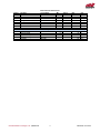
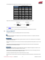
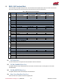
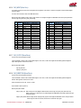
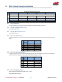
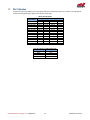
The DAC circuit requires gain calibration. TR11-TR14 adjust the DAC gain. The table below provides, for your reference, a list of the input bits
and their corresponding ideal output voltages for each of the three output ranges.
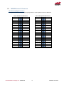
DAC Bit Weight
1111 1111 1111
1000 0000 0000
0100 0000 0000
0010 0000 0000
0001 0000 0000
0000 1000 0000
0000 0100 0000
0000 0010 0000
0000 0001 0000
0000 0000 1000
0000 0000 0100
0000 0000 0010
0000 0000 0001
0000 0000 0000
Table 29: DAC Bit Weights
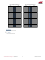
Ideal Output Voltages (mV)
-5 to +5 V 0 to +5 V -10 to +10 V
+4997.56 +4998.78
+9995.12
0 +2500.00
0000.00
-2500.00 +1250.00
-5000.00
-3750.00 +625.00
-7500.00
-4375.00 +312.50
-8750.00
-4687.50 +156.25
-9375.00
-4843.75
+78.13
-9687.50
-4921.88
+39.06
-9843.75
-4960.94
+19.53
-9921.88
-4980.47
+9.77
-9960.94
-4990.24
+4.88
-9980.47
-4995.12
+2.44
-9990.23
-4997.56
+1.22
-9995.12
-5000.00
0.00
-10000.00
0 to +10 V
+9997.56
+5000.00
+2500.00
+1250.00
+625.00
+312.50
+156.25
+78.13
+39.06
+19.53
+9.77
+4.88
+2.44
0.00
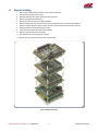
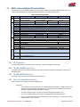
Table 30: Trimpots for Calibrating DAC Gain
DAC
Trimpot
AOUT0
TR11
AOUT1
TR12
AOUT2
TR13
AOUT3
TR14
RTD Embedded Technologies, Inc. | www.rtd.com
56
DM35425HR User’s Manual