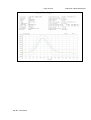
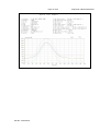
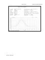
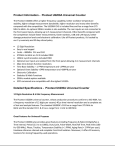
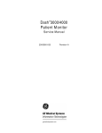
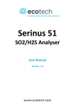
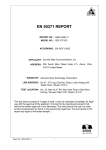
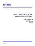
1
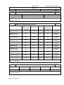
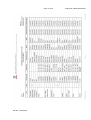
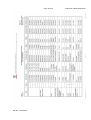
Test Report issued under the responsibility of:
TEST REPORT
IEC 62133, First Edition
Secondary cells and batteries containing alkaline or other non-acid electrolytes –
Safety requirements for portable sealed secondary cells, and for batteries made from
them, for use in portable applications
Report Reference No. ..................... :
CB120416C20 001
Date of issue..................................... :
May 22, 2012
Total number of pages ......................
32
CB Testing Laboratory................... :
Bureau Veritas Consumer Product Services Limited, Taoyuan
Branch
Address ............................................ :
No. 19, Hwa Ya 2nd Rd., Wen Hwa Tsuen, Kwei Shan Hsiang,
Taoyuan Hsien 333, Taiwan
Applicant’s name ............................ :
E-ONE MOLI ENERGY CORP.
Address ............................................ :
10, Dali 2nd Rd., Tainan Science-Based Industrial Park, Shanhua
Dist., Tainan County, 74144, Taiwan
Test specification:
Standard ........................................... :
IEC 62133: 2002 (1st Edition)
Test procedure ................................. :
CB/CCA
Non-standard test method…………..:
N/A
Test Report Form No...................... :
IEC62133A
Test Report Form(s) Originator ........ :
UL International Demko A/S
Master TRF ...................................... :
Dated 2008-02
Copyright © 2008 IEC System for Conformity Testing and Certification of Electrical Equipment
(IECEE), Geneva, Switzerland. All rights reserved.
This publication may be reproduced in whole or in part for non-commercial purposes as long as the IECEE is acknowledged as
copyright owner and source of the material. IECEE takes no responsibility for and will not assume liability for damages resulting from
the reader's interpretation of the reproduced material due to its placement and context.
If this Test Report Form is used by non-IECEE members, the IECEE/IEC logo and the reference to the CB
Scheme procedure shall be removed.
This report is not valid as a CB Test Report unless signed by an approved CB Testing Laboratory and
appended to a CB Test Certificate issued by an NCB in accordance with IECEE 02.
Test item description .....................:
Rechargeable Lithium-Ion Battery
Trade Mark ....................................... :
Molicel or
Manufacturer .................................... :
SOLE ENERGY TECH(ZJGFTZ) CO., LTD.
Model/Type reference....................... :
MCR-1821J/1-H (2ICR19/66)
Ratings ............................................. :
7.4Vdc, 2.4Ah
Page 3 of 32
Report No. CB120416C20 001
Summary of testing:
Tests performed (name of test and test clause):
Testing location:
4.2.2 Vibration
Bureau Veritas Consumer Product Services
Limited, Taoyuan Branch
4.2.4 Temperature cycling
nd
4.3.2 External short circuit
4.3.3 Free fall
4.3.4 Mechanical shock (crash hazard)
The load conditions used during testing:
The unit is charging the empty battery pack and
discharging the full charged battery pack according
to its rating.
Note:
(1) Unless otherwise stated, the charging
procedure for test purposes is carried out in an
ambient temperature of 20±5°C, using the
method declared by the manufacturer.
(2) Prior to charging, the battery shall have been
discharged at 20±5°C at a constant current of
0.2 It A down to a specified final voltage.
Summary of compliance with National Differences:
None
TRF No.: IEC62133A
No. 19, Hwa Ya 2 Rd., Wen Hwa Tsuen, Kwei
Shan Hsiang, Taoyuan Hsien 333, Taiwan
Page 4 of 32
Copy of marking plate
Explanation of the date Code:
TRF No.: IEC62133A
Report No. CB120416C20 001
Page 5 of 32
Report No. CB120416C20 001
Test item particulars .................................................. :
Classification of installation and use ............................ : Built-in, equipment is for ITE product use
Supply Connection........................................................ : Customized connector
...................................................................................... :
...................................................................................... :
Possible test case verdicts:
- test case does not apply to the test object.................. : N/A
- test object does meet the requirement ....................... : P (Pass)
- test object does not meet the requirement ................. : F (Fail)
Testing .......................................................................... :
Date of receipt of test item ............................................ : April 18, 2012
Date (s) of performance of tests ................................... : April 18, 2012 – May 08, 2012
General remarks:
The test results presented in this report relate only to the object tested.
This report shall not be reproduced, except in full, without the written approval of the Issuing testing laboratory.
“(see Enclosure #)” refers to additional information appended to the report.
“(see appended table)" refers to a table appended to the report.
Throughout this report a point is used as the decimal separator.
General product information:
1) The equipment under test (EUT) model MCR-1821J/1-H (2ICR19/66) is a Rechargeable Lithium-Ion
Battery.
2) The maximum ambient temperature is specified as 45 °C for Charging and 60 °C for Discharging.
3) Dimension of the Lithium ion polymer rechargeable battery: (T) 20.6mm by (W) 39.0mm by (L) 71.0mm.
4) Weight: Below 150g.
Test condition:
Temperature: 20±5°C
Relative humidity: 60%
Air pressure: 950 mbar
The test samples were pre-production samples without serial number.
TRF No.: IEC62133A
Page 6 of 32
Report No.: CB120416C20 001
IEC 62133
Clause
Requirement + Test
1
General
Parameter measurement tolerances
2
Result - Remark
P
Both normal and foreseeable
misuses are evaluated in the
report. All control and measure
values were within the
tolerances.
The battery is safe and
continues to function in all
respects under the condition of
intended use.
Cells and batteries subject to reasonably foreseeable The battery is safe and do not
misuse do not present significant hazards.
present significant hazards
under the condition of
reasonably foreseeable
misuse.
2.1
P
P
General Safety Considerations
Cells and batteries subject to intended use be safe
and continue to function in all respects
Verdict
Insulation and Wiring
See below
–Insulation Resistance between an accessible metal
case (excluding electrical contacts) and positive
terminals ≥ 5MΩ.
No accessible metal case.
Internal wiring and insulation are sufficient to
withstand maximum anticipated current, voltage and
temperature requirements
For current: The internal wiring
cable dimension had been
verified to comply with the
Clause 3.1.1 of IEC 60950-1.
P
P
P
N/A
P
For voltage: See List of critical
components table.
For temperature: Evaluated
with temperature test in
Clause 4.2.4.
2.2
Orientation of wiring maintains adequate creepage
and clearance distances between conductors.
Mechanical integrity of internal connections are
sufficient to accommodate conditions of reasonably
foreseeable misuse.
The internal connections were
considered as sufficient to
accommodate conditions of
reasonably foreseeable
misuse.
P
Venting
See below.
P
Battery cases and cells incorporate a pressure relief
mechanism or are constructed so that they relieve
excessive internal pressure at a value and rate that
will preclude rupture, explosion and self-ignition.
The edge of packing which
next to the terminals was
considered as the pressure
relief mechanism, which can
release the pressure during the
abnormal operation.
P
Encapsulant used to support cells within an outer
casing does not cause the battery to overheat during
normal operation no inhibit pressure relief.
The battery is a built in product,
which shall be enclosed in a
rigid case, and will be
evaluated in the final system.
N/A
TRF No.: IEC62133A
Page 7 of 32
Report No.: CB120416C20 001
IEC 62133
Clause
Requirement + Test
Result - Remark
2.3
Temperature/current management
See below.
P
The batteries are designed such that abnormal
temperature rise conditions are prevented.
Protected by limiter in the
certified cell and by
components (U1, Q1, F1 and
F2) in the battery pack circuit.
P
Means is provided to limit current to safe levels
during charge and discharge.
Protected by limiter in the
certified cell and by
components (U1, Q1, F1 and
F2) in the battery pack circuit.
P
Terminal contacts
See below.
P
Terminals have a clear polarity marking on the
external surface of the battery
Customized connector used
and the polarity marking was
provided on the marking plate.
P
2.4
2.5
The size and shape of the terminal contacts ensure
The cross section area of wires
that they can carry the maximum anticipated current. and connector are considered
enough to carry the rating
current of the battery.
P
External terminal contact surfaces are formed from
conductive materials with good mechanical strength
and corrosion resistance.
The connector provides good
mechanical strength to the
copper alloy terminal.
P
Terminal contacts are arranged to minimize the risk
of short circuits.
The connector designation to
prevent short circuit. Proper
spacing and insulation were
maintained to prevent shortcircuit.
P
Assembly of cells into batteries
See below.
P
Cells used in the battery assembly have closely
Two cells in serial are totally
matched capacities, are of the same design, and are identical.
of the same chemistry and same manufacturer.
The battery incorporates separate circuitry to prevent The battery does not have the
cell reversal from uneven charges as the pack is
selective discharge function.
designed for the selective discharge of a portion of its
series connected cells.
2.6
The manufacturer’s procedures
for the inspection of materials,
components and cells which
covers the process of
producing each type of battery
and comply with the
requirement.
TRF No.: IEC62133A
N/A
P
P
Type Test Conditions
Tests were conducted with the number of cells or
batteries as outlined in Table 1 of IEC 62133 with
cells or batteries that were not more than 3 months
old.
P
P
Quality Plan
The manufacture has prepared a quality plan defining
the procedures for the inspection of materials,
components, cells and batteries and which covers
the process of producing each type of cell and
battery.
3
Verdict
The batteries under testing
were less than 3 months old.
P
Page 8 of 32
Report No.: CB120416C20 001
IEC 62133
Clause
Requirement + Test
Result - Remark
Unless noted otherwise in the test methods, testing
was conducted in an ambient of 20°C ± 5°C.
The testing was conducted at
the ambient range of 20°C 25°C.
Verdict
P
P
4
Specific requirements and tests
4.1
Charging procedure for test purposes
The battery was charged in the
ambient temperature according
to manufacturer’s spec.
P
4.2
Intended Use
See below.
P
4.2.1
Continuous Low Rate Charge
See below.
N/A
Fully charged cells are subjected for 28 days to a
charge as specified by the manufacturer.
Certified battery cell used.
N/A
Nickel systems: no fire, no explosion
This is not a nickel system.
N/A
Lithium systems: no fire, no explosion, no leakage
Certified battery cell used.
N/A
Vibration
See below.
P
The measured open circuit voltage of the fully
charged cells or batteries is within anticipated
parameters
Five batteries were fully
charged according to clause
4.1
P
The cells or batteries are subjected to a vibration
sequence as outlined in Table 2 of IEC 62133 with
amplitude of 0.75 mm and a total maximum
excursion of 1.52 mm. The frequency was varied at
the rate of 1 Hz/min between the limits of 10 Hz and
55 Hz. The entire range of frequencies (10 Hz to 55
Hz) and return (55 Hz to 10 Hz) was traversed in 90
min ± 5 min for each mounting position.
Considered for the test.
P
The vibration was applied in each of three mutually
perpendicular directions.
Considered for the test.
P
Results: no fire, no explosion, no leakage
No fire, no explosion, no
leakage during and after the
vibration test.
P
4.2.2
(See Table 4.2.2.)
4.2.3
Moulded case stress at high ambient temperature
See below.
P
Fully charged batteries were placed in an aircirculating oven at a temperature of 70°C ± 2°C for 7
hours. Afterwards, they are removed and allowed to
return to room temperature.
Three batteries were fully
charged and tested for these
conditions.
P
Results: no physical distortion of the battery casing
resulting in exposure if internal components.
No physical distortion of
battery case.
TRF No.: IEC62133A
The used test sample’s no.:
No. P006 to P008
P
Page 9 of 32
Report No.: CB120416C20 001
IEC 62133
Clause
Requirement + Test
Result - Remark
4.2.4
Temperature cycling
See below.
P
Fully charged cells or batteries were subjected to
temperature cycling (-20C, +75C) in forced draught
chambers according to the procedure outlined in
4.2.4 b) and Fig. 1 of IEC 62133.
Five batteries were fully
charged and tested for these
conditions.
P
After the fifth cycle, the cells or batteries were stored
for 7 days prior to examination.
Considered.
P
Results: No fire, no explosion, no leakage
No fire, no explosion, no
leakage after the test.
P
4.3
Reasonably foreseeable misuse
4.3.1
Incorrect installation of a cell (nickel systems only)
4.3.2
Verdict
The used test sample’s no.:
No. P009 to P013
P
Lithium system cell used.
N/A
Four fully charged cells of the same brand, type, size Lithium system cell used.
and age were connected in series with one of the four
cells reversed. The assembly was connected across
a 1-ohm resistor until the vent opens or until the
temperature of the reversed cell returns to ambient
temperature.
N/A
Alternatively, a stabilized dc power supply was used t Lithium system cell used.
simulate the conditions imposed on the reversed cell.
N/A
Results: no fire, no explosion
Lithium system cell used.
N/A
External short circuit
See below.
P
Fully charged cells or batteries were subjected to a
short circuit test at 20°C ± 5°C.
Five batteries were fully
charged and tested for this
condition.
P
The testing was conducted at
23.5 °C
Fully charged cells or batteries were subjected to a
short circuit test at 55°C ± 5°C.
Five batteries were fully
charged and tested for this
condition.
P
The testing was conducted at
55.6 °C.
The external resistance is
measured 10 mΩ maximum.
P
The cells or batteries were tested for 24 h or until the The batteries were tested for
case temperature declined by 20% of the maximum 24 hours.
temperature rise.
P
Results: no fire, no explosion.
P
The external resistance did not exceed 100 mΩ.
No fire, no explosion after the
test.
See Table 4.3.2.
TRF No.: IEC62133A
Page 10 of 32
Report No.: CB120416C20 001
IEC 62133
Clause
Requirement + Test
Result - Remark
4.3.3
Free fall
See below.
Fully charged cells or batteries were dropped 3 times Three batteries were fully
from a height of 1.0 m onto a concrete floor.
charged and tested for this
condition.
Verdict
P
P
The used test sample’s no.:
No. P024 to P026
4.3.4
Results: no fire, no explosion
No fire, no explosion after the
test.
P
Mechanical shock (crash hazard)
See below.
P
Fully charged cells or batteries were subjected to a
total of three shocks of equal magnitude applied in
each of three mutually perpendicular directions. At
least on of the directions was perpendicular to a flat
face. During the initial 3 milliseconds, the minimum
average acceleration was 75 gn. The peak
acceleration was between 125 gn and 175 gn.
Five batteries were fully
charged and tested for this
condition. Refer to the photos
and test charts for detail.
P
Remark:
(1) The used test sample’s
no.: No. P027 to P031.
(2) The EUTs were subjected
to a total of three shocks of
equal magnitude applied in
each of three mutually
perpendicular directions.
(3) As there are two senses
per direction, each sample
will be submitted to a total
of six shock impulses.
4.3.5
4.3.6
Results: no fire, no explosion, no leakage
No fire, no explosion, no
leakage after the test.
Thermal abuse
See below.
N/A
Fully charged cells were placed in a gravity or
circulating air-convention oven. The oven
temperature was raised at a rate of 5°C/min ±
2°C/min to a temperature of 130°C ± 2°C. The cell
remained at that temperature for 10 minutes before
the test was discontinued.
Certified battery cell used.
N/A
Results: no fire, no explosion
Certified battery cell used.
N/A
Crushing of cells
See below.
N/A
Fully charged cells were crushed between two flat
surfaces with a hydraulic ram exerting a force of 13
kN ± 1 kN.
Certified battery cell used.
N/A
A cylindrical or prismatic cell was crushed with its
longitudinal axis parallel to the flat surfaces of the
crushing apparatus.
Certified battery cell used.
N/A
A second set of prismatic cells was tested, rotated 90 Certified battery cell used.
degrees around their longitudinal axis compared to
the first set.
N/A
Results: no fire, no explosion.
N/A
TRF No.: IEC62133A
Certified battery cell used.
P
Page 11 of 32
Report No.: CB120416C20 001
IEC 62133
Clause
Requirement + Test
Result - Remark
4.3.7
Low pressure
See below.
N/A
Fully charged cells are placed in a vacuum chamber
whose internal pressure was gradually reduced to a
pressure equal to or less than 11.6 kPa and held at
that value for 6 hours.
Certified battery cell used.
N/A
Results: no fire, no explosion, no leakage
Certified battery cell used.
N/A
Overcharge for nickel systems
This is not a nickel system.
N/A
A discharged cell or battery was subjected to a high- This is not a nickel system.
rate charge of 2.5 times the recommended charging
current for a time that produced a 250% charge input
(250% of rated capacity).
N/A
Results: no fire, no explosion.
This is not a nickel system.
N/A
Overcharge for lithium systems
See below.
N/A
A discharged cell was charged from a power supply
of ≥ 10 V, at a charging current Irec recommended by
the manufacturer for 2.5 C5/Irec hours..
Certified battery cell used.
N/A
Results: no fire, no explosion.
Certified battery cell used.
N/A
Forced discharge
See below.
N/A
Discharged cells intended for use in multi-cell
applications, were subjected to a reverse charge 1t
1.0 It (A) for 90 minutes.
Certified battery cell used.
N/A
Results: no fire, no explosion
Certified battery cell used.
N/A
Cell protection against a high charging rate (lithium
systems only)
See below.
N/A
Discharged cells were charged at three times the
charging current recommended by the manufacturer
until the cells was fully charged or an internal safety
devices cut off the charge current before the cell
became fully charged.
Certified battery cell used.
N/A
Results: no fire, no explosion
Certified battery cell used.
N/A
Information for safety
See below.
P
Information is provided to equipment manufacturers
in the form of instructions to minimize and mitigate
hazards associated with the cells or batteries in
accordance with guidelines outlined in informative
Annex A.
Provided in the product
specification, which will
considered during the end
product investigation.
P
Information is provided to end-users in the form of
instructions to minimize and mitigate hazards
associated with the batteries in accordance with
guidelines outlined in informative Annex B.
Provided in the product
specification, which will be
merged into the user manual of
the end product.
P
4.3.8
4.3.9
4.3.10
4.3.11
5
TRF No.: IEC62133A
Verdict
Page 12 of 32
Report No.: CB120416C20 001
IEC 62133
Clause
Requirement + Test
6
Marking
6.1
Cell Marking
See below.
N/A
Nickel system cells are marked in accordance with
IEC 61951-1, -2, IEC 61440, or IEC 61436 as
applicable. See Copy of Marking Plate item in the
beginning of this report.
This is not a nickel system.
N/A
Lithium system cells are marked in accordance with
IEC 61960. See Copy of Marking Plate item in the
beginning of this report.
The product is Lithium-ion
battery.
N/A
Battery Marking
See below.
Batteries of nickel systems are marked in
accordance with IEC 61951, or IEC 61951 -2 as
applicable. See Copy of Marking Plate item in the
beginning of this report
This is not a nickel system.
6.2
6.3
7
Result - Remark
Verdict
P
N/A
Batteries of lithium system are marked in accordance See copy of the marking plate.
with IEC 61960. See Copy of Marking Plate item in
the beginning of this report.
P
Batteries are marked with the cautionary marks.
See copy of the marking plate.
P
Other Information
See below.
P
Disposal instructions are marked on the battery or
The disposal instructions are
supplied in the information packaged with the battery. provided in the specification.
P
Recommended charging instruction are marked on
the battery or supplied in the information packaged
with the battery.
The recommended charging
instructions are provided in the
specification.
P
The package method had been
Indicated in the product
specification, which had been
passed the environmental test
to ensure the well packaging
method and to prevent the
unintentional electrical
conduction.
P
Packaging
Cells or batteries were provided with packaging that
was adequate to avoid mechanical damage during
transport, handling and stacking. The materials and
pack design was chosen to prevent the development
of unintentional electrical conduction, corrosion of the
terminal and ingress of moisture.
TRF No.: IEC62133A
Page 13 of 32
Report No.: CB120416C20 001
IEC 62133
Clause
Requirement + Test
Result - Remark
2.1 – 2.5
TABLE: List of critical Components
Type/Model
Verdict
P
Object/part No.
Manufacturer/
trademark
Technical Data
Standard
Marks of
Conformity
Battery Cell
(2S)
E-ONE MOLI
ENERGY
CORP.
ICR18650J
3.7Vdc,
2370mAh,
Lithium-Ion type
IEC 62133:
2002, UL
1642
CB (Ref
Certificate No.:
Fr607332/A1),
UL
PCB
Various
Various
V-1 min., 105°C
min.
UL 796
UL
Fuse (F1)
Tamura Thermal T6D
Device
Corporation
50Vdc, 9A,
139°C
EN 60691:
VDE (Ref
2003+A1:2007 Certificate No.:
40009915)
Fuse (F2)
Polytronics
SMFS1206P500 32Vdc, 5A
technology Corp
UL 248-1
UL (E331807)
- Alternate use
Littelfuse Inc
F1206HI5000V0 32Vdc, 5A
32TM
UL 248-1
UL (E232989)
Protection IC
(U1)
Seiko
Instruments Inc.
S-8242B
--
--
Tested in the
appliance
MOSFET
(Q1)
International
Rectifier
IRF7313PbF
--
--
Tested in the
appliance
Supplementary information:
N/A
TABLE: 4.2.1 Continuous Low Rate Charge Test
Model
Recommended
Charging Method,
CC, CV, or CC/CV
--
--
Recommended
Recommended OCV at Start
Charging Voltage Charging Current of Test, Vdc
Vc, Vdc
Irec, A
--
--
--
Results
--
Supplementary information:
P
TABLE: 4.2.2 – Vibration Test
Model
OCV at Start of Test, Vdc
Results
MCR-1821J/1-H (Sample no.: P001)
8.41 at X / Y / Z axis
No fire, no explosion, no leakage
MCR-1821J/1-H (Sample no.: P002)
8.42 at X / Y / Z axis
No fire, no explosion, no leakage
MCR-1821J/1-H (Sample no.: P003)
8.41 at X / Y / Z axis
No fire, no explosion, no leakage
MCR-1821J/1-H (Sample no.: P004)
8.42 at X / Y / Z axis
No fire, no explosion, no leakage
MCR-1821J/1-H (Sample no.: P005)
8.42 at X / Y / Z axis
No fire, no explosion, no leakage
Supplementary information:
- No fire or explosion
- No leakage
TRF No.: IEC62133A
Page 14 of 32
Report No.: CB120416C20 001
IEC 62133
Clause
Requirement + Test
Result - Remark
Verdict
N/A
TABLE: 4.3.1 – Incorrect Installation of a Cell Test (Nickel Systems)
Model
OCV (reversed cell), Vdc
Results
--
--
--
Supplementary information:
Li-polymer cell used.
P
TABLE: 4.3.2 – External Short Circuit Test
Model
Ambient (At
20°C ± 5ºC or
55°C ± 5°C)
OCV at start
of test, Vdc
Resistance Maximum Case
of Circuit,
Temperature
Ω
Rise ∆T, °C
Results
MCR-1821J/1-H
(Sample no.: P014)
23.5
8.42
0.01
0.6
No fire, no
explosion
MCR-1821J/1-H
(Sample no.: P015)
23.5
8.43
0.01
0.5
No fire, no
explosion
MCR-1821J/1-H
(Sample no.: P016)
23.5
8.42
0.01
0.5
No fire, no
explosion
MCR-1821J/1-H
(Sample no.: P017)
23.5
8.41
0.01
0.6
No fire, no
explosion
MCR-1821J/1-H
(Sample no.: P018)
23.5
8.42
0.01
0.6
No fire, no
explosion
MCR-1821J/1-H
(Sample no.: P019)
55.6
8.41
0.01
1.4
No fire, no
explosion
MCR-1821J/1-H
(Sample no.: P020)
55.6
8.42
0.01
1.3
No fire, no
explosion
MCR-1821J/1-H
(Sample no.: P021)
55.6
8.41
0.01
1.5
No fire, no
explosion
MCR-1821J/1-H
(Sample no.: P022)
55.6
8.40
0.01
1.5
No fire, no
explosion
MCR-1821J/1-H
(Sample no.: P023)
55.6
8.41
0.01
1.4
No fire, no
explosion
Supplementary information:
- No fire or explosion
N/A
TABLE: 4.3.8 – Overcharge Test (Nickel Systems)
Model
OCV prior to
charging, Vdc
Maximum Charge
Current, A
Time for Charging,
h
Results
--
--
--
--
--
Supplementary information:
Li-polymer cell used.
TRF No.: IEC62133A
Page 15 of 32
Report No.: CB120416C20 001
IEC 62133
Clause
Requirement + Test
Result - Remark
Verdict
N/A
TABLE: 4.3.9 – Overcharge Tests (Lithium Systems)
Model
OCV at start of
test, Vdc
Maximum
Charging
Current, mA
Maximum
Charging
Voltage, Vdc
Total Time of
Charging, h
Results
--
--
--
--
--
--
Supplementary information:
N/A
TABLE: 4.3.10 – Forced Discharge Test
Model
OCV before
application of
reverse charge, Vdc
Measured Reverse
Charge It, A
Total Time for
Reversed Charge
Application, Min
Results
--
--
--
--
--
Supplementary information:
N/A
TABLE: 4.3.11 – Cell Protection Against a High Charging Rate Test (Lithium
Systems)
Model
OCV at start of test,
Vdc
Maximum Charging
Current, mA
Maximum Charging
Voltage, Vdc
Results
--
--
--
--
--
Supplementary information:
TRF No.: IEC62133A
Page 16 of 32
Report No. CB120416C20 001
List of test equipment used:
(Note: This is an example of the required attachment. Other forms with a different layout but
containing similar information are also acceptable.)
Clause
Measurement /
testing
See next
page
TRF No.: IEC62133A
Testing / measuring equipment /
material used
Range used
Calibration
date
Page 17 of 32
TRF No.: IEC62133A
Report No. CB120416C20 001
Page 18 of 32
TRF No.: IEC62133A
Report No. CB120416C20 001
Page 19 of 32
TRF No.: IEC62133A
Report No. CB120416C20 001
Page 20 of 32
Report No. CB120416C20 001
MAXIMUM UNCERTAINTIES OF MEASUREMENTS
This table indicates the maximum values of uncertainties associated with the tests being
able to be present in this document.
Type of measurement
Generic measure of electrical value by direct reading of
digital instrument)
Voltage (V)
Current (A)
Power (W)
Resistance (Ohms)
Generic measure of time
Generic measure of length value
Generic measure of weight value
Continuous low-rate charging (Voltage, Current, Time)
Vibration (Voltage, Current, Time)
Moulded case stress at high ambient temperature (Voltage,
Current, Time)
Temperature cycling (Voltage, Current, Time)
Incorrect installation of a cell (nickel systems only) (Voltage,
Current, Temperature, Time, Capacity)
External short circuit (Temperature, Time, Capacity)
Free fall (Voltage, Current, Dimension)
Mechanical shock (crash hazard) (Voltage, Current,
Temperature, Time)
Thermal abuse (Voltage, Current, Temperature, Time)
Crushing of cells (Voltage, Current)
Low pressure (Voltage, Current, Temperature, Time,
Dimension)
Overcharge for nickel systems (Voltage, Current, Time)
Overcharge for lithium systems (Voltage, Current, Time)
Forced discharge (Voltage, Current, Time)
Cell protection against a high charging rate (lithium systems
only) (Voltage, Current)
TRF No.: IEC62133A
Uncertainty of measurement (k=2)
(V) meter accuracy 0.1%
(A) meter accuracy 0.5%
(W) meter accuracy 1.0%
(Ohms) meter accuracy 1.5%
+/- 0.38 Second
caliper (0-200mm): +/-0.15 mm
tape measure (0-500cm): +/-1.4 mm
scale (0-600g): +/- 0.55 g
balance (0-150kg): +/- 15.95 g
+/- 0.276%
+/- 3%
+/- 0.6%
+/- 0.6%
+/- 0.74%
+/- 0.8%
+/- 0.11%
+/- 11.8%
+/- 0.738%
+/- 0.216%
+/- 5.013%
+/- 0.50%
+/- 0.22%
+/- 0.52%
+/- 0.24%
Page 21 of 32
Top view for the battery
Bottom view for the battery
TRF No.: IEC62133A
Report No. CB120416C20 001
Page 22 of 32
The view for the soft pack and enclosure
Top view of soft pack
TRF No.: IEC62133A
Report No. CB120416C20 001
Page 23 of 32
Bottom view of soft pack
The view of PCB
TRF No.: IEC62133A
Report No. CB120416C20 001
Page 24 of 32
Vibration test condition-1 (X axis direction)
Vibration test condition-2 (Y axis direction)
TRF No.: IEC62133A
Report No. CB120416C20 001
Page 25 of 32
Vibration test condition-3 (Z axis direction)
Shock test condition-1 (X axis direction)
TRF No.: IEC62133A
Report No. CB120416C20 001
Page 26 of 32
Shock test condition-2 (Y axis direction)
Shock test condition-3 (X axis direction)
TRF No.: IEC62133A
Report No. CB120416C20 001
Page 27 of 32
Vibration test chart-X axis direction
TRF No.: IEC62133A
Report No. CB120416C20 001
Page 28 of 32
Vibration test chart-Y axis direction
TRF No.: IEC62133A
Report No. CB120416C20 001
Page 29 of 32
Vibration test chart-Z axis direction
TRF No.: IEC62133A
Report No. CB120416C20 001
Page 30 of 32
Shock test chart-X axis direction
TRF No.: IEC62133A
Report No. CB120416C20 001
Page 31 of 32
Shock test chart-Y axis direction
TRF No.: IEC62133A
Report No. CB120416C20 001
Page 32 of 32
Shock test chart-Z axis direction
TRF No.: IEC62133A
Report No. CB120416C20 001