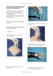
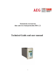
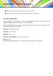
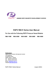
1
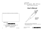
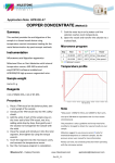
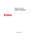
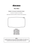
ETHOS D User Manual - Rev. 0/2001
MDR TECHNOLOGY
Milestone patented microwave digestion rotor
(MDR) technology provides analysts with
unsurpassed performance capabilities and the
highest standard of safety in closed vessel
microwave digestion.
MDR rotors hold multiple microwave digestion
vessels in a high strength one-piece “mono-bloc”
rotor body.
This unique design securely retains sample vessels
during microwave digestion and subsequent venting
of decomposition gases, for maximum user safety.
The digestion vessels used in MDR rotors have no
molded or machined threads to be chemically
attacked and weakened by acid vapors during
vessel venting and opening.
This unique feature is an important factor in the
durability and safety of Milestone digestion vessels.
All digestion vessels in MDR rotors are protected
by a patented re-closing (vent and reseal) relief
valve mechanism.
Vessels fitted into a MDR rotor body are sealed for
microwave digestion and proper relief valve
functioning using a calibrated torque wrench.
The torque wrench ensures vessels are sealed for
maximum operating pressure, and will safely vent
when a buildup of decomposition gases in excess of
vessel’s maximum operating pressure is reached.
Microwave digestion of organic samples frequently
involves exothermic reactions, which
instantaneously generate large amount of
decomposition gases (CO2 and NOX) as the sample
is oxidized.
For proper over pressurization protection of
microwave digestion vessels, the venting capacity
of the relief device must be equal or higher than the
rate of decomposition gas formation.
Only Milestone’s relief valve is capable of
instantaneously venting excess decomposition gases
and resealing the vessel until the digestion
procedure is completed.
The digested sample is retained inside the vessel for
analysis.
7.1
MDR MAJOR COMPONENTS
The rotor consists of a high-density polypropylene
core in which a number of niches have been
“carved” along the periphery by a numerical control
machining center.
The compact core has the required strength to
withstand the extreme pressure generated inside the
vessel during digestion.
The core tolerates this pressure without any
deformation and therefore with high safety.
Special plastic compression screws are located on
the top of the rotor next to each “niche”.
Suitable pressure is applied to the dome-shaped
spring holding the cover to the top of the vessel by
tightening the screws to the appropriate degree.
The dome-shaped, flattop spring is the “heart” of
the MDR technology and is made of HTC, a new
high-performance plastic.
HTC is crystalline and can act as a powerful and
very reliable spring.
The adapter plate is placed on top of the cover.
Made of a plastic with high resistance to
mechanical compression, it allows a very
homogeneous and repeatable distribution of the
preset pressure limit.
The cover has a flat bottom rim and perfectly fits
the top rim of the vessel.
Sealing between cover and vessel takes place on a
very large surface area without any intermediate
seal ring, which could deteriorate in contact with
acid vapors.
The elimination of a threaded cover prevents all
problems connected with thread deformation or
impurities on threads.
The vessel has normally a volume of 100 mL.
A high resistant HTC safety shield prevents lateral
deformation of the vessel.
MDR technology - Monobloc Page 1
ETHOS D User Manual - Rev. 0/2001
MATERIALS USED FOR THE MANUFACTURE
OF MDR VESSELS AND SAFETY SHIELDS
TFM TEFLON
TFM is often used for the manufacture of covers
and vessels of the MDR rotors. TFM is a Hoechst
trade name for chemically modified PTFE. TFM
Teflon has a very dense structure with smooth
surface and low permeability to gases and vapors.
TFM Teflon is chemically inert to most mineral
acids and combinations thereof.
It is a thermal insulator, with a very high stability to
temperature extremes. TFM Teflon is microwave
transparent. Its maximum working temperature for
extended use is 260°C, for short time 300°C. The
melting range is 320-340°C.
PFA TEFLON
PFA is often used for the manufacture of vessels of
the MDR rotors. PFA Teflon is a melt-processable
fluoroplastic material, which can be extruded and
therefore manufactured in relatively low-cost
vessels. It shows a good all-round chemical
resistance. It is microwave transparent and thermal
insulator. The maximum working temperature is
around 220°C; the melting temperature is about
300°C.
HTC plastics are used for the manufacture of safety
spring, adapter plate and safety shield.
They are characterized by the sequence ether-etherketon-keton.
When HTC are used for the safety shield they are
reinforced with glass fiber.
HTC have high mechanical strength to high
temperatures and good chemical resistance.
The maximum service temperature for extended use
is 250°C.
MDR SAFETY
The drawing below clearly show the instantaneous
release of overpressure due to the deformation of
the HTC safety spring.
The figure at left represents a vessel in normal
working conditions.
When pressure increases over the maximum spring
working pressure (figure in the center), the entire
cover is allowed to lift up because of the elastic
deformation of the safety spring.
The overpressure is instantaneously released thanks
to the large surface area.
The larger the surface area the shorter the time
required to release the pressure.
Once the pressure inside the vessel has returned
within the vessel limit, the cover reseals the vessel,
permitting the operator to continue with the acid
digestion without any loss (figure at right).
HTC
MDR technology - Monobloc Page 2
ETHOS D User Manual - Rev. 0/2001
This is the unique operating principle of the
microwave digestion rotor technology of Milestone.
An indicator ring located next to the cover remains
in the upper position in case of vessel venting.
The picture shows at right a vessel in normal
conditions and at left a vessel after venting.
MDR-1000/6S
therefore most analytical balances may be used for
the purpose (picture).
Tare the vessel and directly weigh the sample by
placing it inside the vessel (picture). Try to reduce
as much as possible sample transfer, to avoid any
contamination. Introduce the TFM Teflon vessel
into the HTC protection shield.
The MDR-1000/6S high pressure rotor contains 6
vessels for acid digestion of routine and difficult
samples at operating pressure up to 100bar
(1.450psi).
HOW TO OPERATE WITH THE MDR-1000/6S
ROTOR
SAMPLE WEIGHING, REAGENTS ADDITION
AND VESSEL CAPPING
Place a TFM Teflon vessel directly on the balance
plate.
The weight of the TFM Teflon vessel is about 120g,
WARNING
The wall surfaces of the HTC protection shield as
well as the outer wall of the TFM Teflon vessel
must be dry and clean.
Damages may occur otherwise!
MDR technology - Monobloc Page 3
ETHOS D User Manual - Rev. 0/2001
Add suitable reagents to the sample.
When part of the sample is left on the inner wall of
the TFM Teflon vessel, try to wet it by adding acids
drop by drop (picture).
Gently swirl the solution, to homogenize the sample
with the acid. Place the TFM Teflon cover on the
TFM Teflon vessel. Push it by end and check that
the cover fits well onto the vessel (picture).
Now put the TFM Teflon indicator ring on the
cover and push it down completely, until it fits the
groove of the HTC safety shield, as shown by the
next picture.
Position the polypropylene rotor body on the work
station (picture).
Place now the HTC adapter plate on the TFM
Teflon cover, with the flat part of it at facing
downwards, to have the space for the HTC safety
spring on the top side (picture).
Place the HTC safety spring onto the HTC adapter
plate (picture).
Introduce the vessel vertically into one of the
numbered niches carved along the periphery of the
6-position polypropylene rotor body.
MDR technology - Monobloc Page 4
ETHOS D User Manual - Rev. 0/2001
Notice the position of the venting hole located in
the TFM Teflon indicator ring. The hole must face
outside, so that in case of venting no hot acid
vapors can damage the polypropylene rotor body
(picture).
Repeat the same operations for the remaining nine
vessels; then put the external protection
ring around the rotor body (picture).
It may be useful now to fix the vessel inside its
location, without a complete closing. Take the
torque wrench and remove the plastic adaptor
(picture).
Take the torque wrench and set the indicator to the
“CLOSE” position, as shown in the next picture.
Use the adaptor to fix the vessels, as shown in the
next picture.
Tighten the HTC screw in the upper part of the
rotor body using the torque wrench.
Make long rotations (refer to the two next pictures)
instead of short ones and do proceed slowly until
you hear a clicking sound informing that the vessel
is properly closed inside its niche.
WARNING
Stop turning the torque wrench when the click is
heard.
In fact the torque wrench may overload the HTC
safety spring if further rotation is applied.
MDR technology - Monobloc Page 5
ETHOS D User Manual - Rev. 0/2001
Make slow 90° rotations with the torque wrench, to
get a better control of the correct closing of the
vessel (click sound).
Slide-in the MDR-1000/6S rotor inside the
microwave cavity of the ETHOS (picture).
Turn the rotor until it matches the drive adaptor
located at the center of the microwave cavity base
(picture).
The MDR-1000/6S rotor is now ready to be
introduced inside the ETHOS; open the door of the
microwave unit by pressing down the door handle
(picture).
MDR technology - Monobloc Page 6
ETHOS D User Manual - Rev. 0/2001
Close the door of the ETHOS (picture).
Switch on the ETHOS (picture) and start a suitable
microwave acid digestion program.
MDR technology - Monobloc Page 7
ETHOS D User Manual - Rev. 0/2001
SETUP OF THE REFERENCE VESSEL, USED
FOR TEMPERATURE CONTROL
Notice the reference cover, provided with one port,
and the thermowell. The thermowell is made of
ceramic, and it is Teflon coated to avoid any sort of
damage.
Push the HTC screw, along with the TFM sealing
ring and the ceramic thermowell, until the HTC
screw is in contact with the TFM Teflon cover.
Slide-in the thermowell into the Teflon cover.
The open end of the thermowell should be of course
left in the upper part of the Teflon cover, to allow
the subsequent introduction of the thermocouple.
Use the HTC tool supplied to tighten the HTC
screw into the TFM Teflon cover, as shown by the
next picture.
Introduce the TFM Teflon sealing ring, as shown
by the next picture.
Locate now the HTC fixing screw onto the TFM
Teflon sealing ring.
MDR technology - Monobloc Page 8
ETHOS D User Manual - Rev. 0/2001
The HTC screw should remain approximately 1
mm above the surface of the TFM Teflon cover.
The setup of the reference cover for temperature
control is not a routine operation, so it must be
carried out only once.
It is however important to check regularly that the
HTC screw does not feel loose on the TFM Teflon
cover.
It is therefore recommended to tighten the HTC
screw from time to time.
Furthermore, whenever the HTC screw shows signs
of corrosion, typically a yellowish color, remove it
from the TFM Teflon cover and replace it along
with the TFM Teflon sealing ring.
The vessel used for temperature control should
contain the same sample, the same sample size and
the same reagent as the remaining vessels, as this
vessel is used as reference.
☞
the HTC adapter plate has to match the indentation
of the TFM Teflon cover; you will notice also that
the HTC screw will match the grove machined in
the bottom part of the TFM Teflon cover.
Put the special HTC safety spring onto the HTC
adapter plate.
The reference HTC spring differs from the others; it
has a smaller diameter to allow the introduction of
the thermocouple into the vessel.
WARNING
It is recommended to use at least 8 mL of
solution inside the vessel, to allow the
temperature sensor to be in contact with
the liquid.
Place the reference cover onto the vessel, as shown
by the next picture.
Introduce the reference vessel just assembled into
the position number one of the rotor.
The special HTC adapter plate goes on the
reference TFM Teflon cover. The indentation of
MDR technology - Monobloc Page 9
ETHOS D User Manual - Rev. 0/2001
Put the protection ring around the rotor body.
Tighten the reference vessel in the same way as the
other vessels.
Take the torque wrench and set the indicator to the
“close” position, as shown in the next picture.
Introduce now the thermocouple into the reference
vessel, simply sliding-in the sensor through the hole
in the HTC screw of the rotor.
Tighten the HTC screw in the upper part of the
rotor body using the torque wrench.
Make long rotations instead of short ones and do
proceed slowly until you hear a clicking sound
informing that the vessel is properly closed inside
its niche.
☞
WARNING
Stop turning the torque wrench when a
click is heard.
In fact the torque wrench may overload
the HTC safety springs if further rotation
is applied.
Detail of the upper part of the rotor.
Notice the hole for the thermocouple.
This is aligned with the thermowell, therefore
allowing the temperature sensor to be fully
introduced in the vessel.
Fully introduce the temperature sensor into the
thermowell, until the snap connector is fixed.
MDR technology - Monobloc Page 10
ETHOS D User Manual - Rev. 0/2001
A beep sound will be heard.
Plug-in now the temperature sensor.
Bend the temperature sensor as shown by the next
picture.
This positioning of the rotor and of the sensor is
now correct.
The rotor is now ready to be introduced inside the
ETHOS; open the door of the microwave unit and
introduce the rotor into the cavity.
Gently turn the rotor until it matches the HTC rotor
drive located in the center of the microwave cavity
bottom.
Close the door of the ETHOS and start a digestion
program (refer to the Milestone cookbook).
Unplug the jumper of the ATC-400 Automatic
Temperature Control device of the ETHOS.
COOLING DOWN AND UNCAPPING THE
VESSEL
Once the digestion program is completed, high
temperature and pressure are reached inside the
vessels, according with the sample preparation
procedure applied.
It is therefore necessary to cool down the rotor
before opening the vessels.
To facilitate this operating step Milestone has
developed a cooling system able to reduce the
cooling time to about 10 minutes.
For the monobloc rotor, Introduce the rotor body
complete with vessels and protection ring inside the
cooling system (picture above).
MDR technology - Monobloc Page 11
ETHOS D User Manual - Rev. 0/2001
For segmented rotor, introduce the individual
segements.
Put the cover back on the cooling system itself
(picture).
Turn off the water supply and move the rotor body
from the cooling system to the work station,
preferably located under a fume hood.
Dry with the utmost care rotor and vessels prior
uncapping.
Take the torque wrench and set the indicator to the
“OPEN” position, as shown in the next picture.
Turn on the water supply and let the water flow in
for approximately 10-15 minutes (picture).
Place the rotor complete with vessels on the work
station, located under a fume hood.
Carefully loosen the screw in the upper part of the
rotor body, by using the tension wrench.
Open vessels very slowly, since a certain pressure
may still be present (depending on sample type)
even if temperature is as low as room temperature.
Open the vessel opposite to your position, as shown
by the next two pictures.
Get a good control of the opening step rotating the
torque wrench with wide angles.
MDR technology - Monobloc Page 12
ETHOS D User Manual - Rev. 0/2001
Take the vessels out of the rotor body (picture).
Carefully take up the vessel cover together with the
TFM Teflon protection ring (picture).
Remove the external protection (picture).
Rinse the lower part of the TFM Teflon cover with
distilled water, collecting the same inside the vessel
(picture).
MDR technology - Monobloc Page 13
ETHOS D User Manual - Rev. 0/2001
Slide the TFM Teflon vessel out of the HTC
protection shield (picture).
Pour the solution in a laboratory volumetric flask,
washing repeatedly the TFM Teflon vessel with
distilled water (picture).
Repeat the same operation with all vessels in the
rotor.
Your samples are now ready to be analyzed.
MDR technology - Monobloc Page 14