1
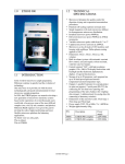
ETHOS D User Manual - Rev. 0/2001
MPR-300/12S and HPR-1000/10S
SEGMENTED ROTORS
The MPR-300/12S medium pressure segmented
rotor contains 12 vessels for acid digestion of
routine and difficult samples at operating pressure
up to 30bar (435psg).
The HPR-1000/10S high pressure segmented rotor
contains 10 vessels for operating pressure up to
100bar (1.450psig).
HOW TO OPERATE WITH THE SEGMENTED
ROTORS
Use the adaptor to fix the vessels, as shown in the
next picture.
SAMPLE WEIGHING, REAGENTS ADDITION
AND VESSEL CAPPING
See MDR-1000/6S
Position the polypropylene rotor segment on the
work station (picture).
Take the torque wrench and set the indicator to the
“CLOSE” position, as shown in the next picture.
Take the torque wrench and remove the plastic
adapter (picture).
Tighten the HTC screw in the upper part of the
rotor body using the torque wrench.
MDR technology – Segmented Page 1
ETHOS D User Manual - Rev. 0/2001
Make long rotations (refer to the two next pictures)
instead of short ones and do proceed slowly until
you hear a clicking sound informing that the vessel
is properly closed inside its niche.
WARNING
Stop turning the torque wrench when the click is
heard.
In fact the torque wrench may overload the HTC
safety spring if further rotation is applied.
Make slow 90° rotations with the torque wrench, to
get a better control of the correct closing of the
vessel (click sound).
Repeat this operation for all of the segments.
Switch on the ETHOS (picture) and start a suitable
microwave acid digestion program.
Place the rotor assembly on the drive adapter
located in the center of the microwave cavity. One
by one insert the rotor segments onto the rotor
assembly (already located in the cavity).
Close the door of the ETHOS (picture).
SETUP OF THE REFERENCE VESSEL, USED
FOR TEMPERATURE CONTROL
MDR technology – Segmented Page 2
ETHOS D User Manual - Rev. 0/2001
Notice the reference cover, provided with one port,
and the thermowell.
Push the HTC screw, along with the TFM sealing
ring and the ceramic thermowell, until the HTC
screw is in contact with the TFM Teflon cover.
The thermowell is made of ceramic, and it is Teflon
coated to avoid any sort of corrosion.
Use the HTC tool supplied to tighten the HTC
Slide-in the thermowell into the Teflon cover.
The open end of the thermowell should be of course
left in the upper part of the Teflon cover, to allow
the subsequent introduction of the thermocouple.
screw into the TFM Teflon cover, as shown by the
next picture.
Introduce the TFM Teflon sealing ring, as shown
by the next picture.
Locate now the HTC fixing screw onto the TFM
Teflon sealing ring.
The HTC screw should remain approximately 1
mm above the surface of the TFM Teflon cover.
The setup of the reference cover for temperature
control is not a routine operation, so it must be
carried out only once. It is important, however, to
check regularly that the HTC screw does not feel
loose on the TFM Teflon cover.
MDR technology – Segmented Page 3
ETHOS D User Manual - Rev. 0/2001
The special HTC adapter plate goes on the
reference TFM Teflon cover. The indentation of
the HTC adapter plate has to match the indentation
of the TFM Teflon cover; you will notice also that
the HTC screw will match the grove machined in
the bottom part of the TFM Teflon cover.
It is therefore recommended to tighten the HTC
screw from time to time.
Furthermore, whenever the HTC screw shows signs
of corrosion, typically a yellowish color, remove it
from the TFM Teflon cover and replace it along
with the TFM Teflon sealing ring.
The vessel used for temperature control should
contain the same sample, the same sample size and
the same reagent as the remaining vessels, as this
vessel is used as reference.
☞
Place the special HTC safety spring onto the HTC
adapter plate.
The reference HTC spring differs from the others; it
WARNING
It is recommended to use at least 8 mL of
solution inside the vessel, to allow the
temperature sensor to be in contact with
the liquid.
has a smaller diameter to allow the introduction of
the thermocouple into the vessel.
Now place the reference cover onto the vessel, as
shown by the next picture.
Introduce the reference vessel just assembled into
the reference polypropylene segment.
MDR technology – Segmented Page 4
ETHOS D User Manual - Rev. 0/2001
This is aligned with the thermowell, therefore
allowing the temperature sensor to be fully
introduced in the vessel.
Fully introduce the temperature sensor into the
thermowell, until the snap connector is fixed.
Tighten the reference vessel in the same way as the
other vessels.
Introduce the segmented rotor top plate; the plate is
fixed by the connectors to each individual
polypropylene segment.
Introduce now the thermocouple into the reference
vessel, simply sliding-in the sensor through the hole
in the HTC screw of the reference segment.
Detail of the upper part of the reference vessel.
Notice the hole for the thermocouple.
Lift up one side of the top plate to facilitate the
introduction of the reference segment; then relocate
back the top plate in its position.
MDR technology – Segmented Page 5
ETHOS D User Manual - Rev. 0/2001
Plug-in now the temperature sensor.
Bend the temperature sensor as shown by the next
picture.
This positioning of the rotor and of the sensor is
now correct.
Detail of the upper part of the reference segment
complete with rotor top plate.
Notice the temperature sensor snap, which must be
free to turn.
Close the door of the ETHOS and start a digestion
program (refer to the Milestone cookbook).
Unplug now the jumper of the ATC-400 Automatic
Temperature Control device of the ETHOS.
A beep sound will be heard.
COOLING DOWN AND UNCAPPING THE
VESSELS
After the heating cycle has been completed, allow a
5-minute cooling time of the vessels into the
microwave cavity.
Then open the door of the ETHOS and carefully the
thermocouple from the reference vessel.
☞
WARNING
MDR technology – Segmented Page 6
ETHOS D User Manual - Rev. 0/2001
Due to a substantial expansion of the
plastics used at high temperature, the
removal of the thermocouple should be
done only when the inner temperature of
the vessel is approximately 180°C.
Once the digestion program is completed, high
temperature and pressure are reached inside the
vessels, according with the sample preparation
procedure applied.
It is therefore necessary to cool down the rotor
before opening the vessels.
The rotor may be air cooled inside the ETHOS and
in such case the cooling time is around 25 minutes
(approximately 6-8°C/minute).
Alternatively, the segments may be removed from
the ETHOS microwave cavity and immersed in a
water bath.
In such case the cooling time is around 10-15
minutes (approximately 10-15°C/minute).
Once reached a temperature close to room
temperature the vessels can be opened.
Take the torque wrench and set the indicator to the
“open” position, as shown in the next picture.
For the monobloc rotor, Introduce the rotor body
complete with vessels and protection ring inside the
cooling system (picture above).
For segmented rotor, introduce the individual
segements.
Put the cover back on the cooling system itself
(picture).
COOLING DOWN AND UNCAPPING THE
VESSEL
Once the digestion program is completed, high
temperature and pressure are reached inside the
vessels, according with the sample preparation
procedure applied.
It is therefore necessary to cool down the rotor
before opening the vessels.
To facilitate this operating step Milestone has
developed a cooling system able to reduce the
cooling time to about 10 minutes.
MDR technology – Segmented Page 7
ETHOS D User Manual - Rev. 0/2001
Turn on the water supply and let the water flow in
for approximately 10-15 minutes (picture).
Turn off the water supply and move the rotor body
from the cooling system to the work station,
preferably located under a fume hood.
Dry with the utmost care rotor and vessels prior
uncapping.
Take the torque wrench and set the indicator to the
“OPEN” position, as shown in the next picture.
Open the vessel opposite to your position, as shown
by the next two pictures.
Get a good control of the opening step rotating the
torque wrench with wide angles.
Remove the external protection (picture).
Place the rotor complete with vessels on the work
station, located under a fume hood.
Carefully loosen the screw in the upper part of the
rotor body, by using the tension wrench.
Open vessels very slowly, since a certain pressure
may still be present (depending on sample type)
even if temperature is as low as room temperature.
Take the vessels out of the rotor body (picture).
Carefully take up the vessel cover together with the
TFM Teflon protection ring (picture).
MDR technology – Segmented Page 8
ETHOS D User Manual - Rev. 0/2001
Pour the solution in a laboratory volumetric flask,
washing repeatedly the TFM Teflon vessel with
distilled water (picture).
Rinse the lower part of the TFM Teflon cover with
distilled water, collecting the same inside the vessel
(picture).
Repeat the same operation with all vessels in the
rotor.
Your samples are now ready to be analysed.
Slide the TFM Teflon vessel out of the HTC
protection shield (picture).
MDR technology – Segmented Page 9
ETHOS D User Manual - Rev. 0/2001
MDR ROTORS MAINTENANCE
SAFETY SPRING
As general rules:
• do not use any organic solvent to clean or dry
any part of the rotor, with the exception of the
TFM Teflon covers and of the TFM or PFA
Teflon vessels.
• Dry every component including the vessels
thoroughly with paper towel or cloth before
placing the rotor in the microwave unit.
Any moisture or acid trace would heat up in the
microwave field and it could possibly damage
the components.
This is especially true if any trace of water or
acid is left between the internal wall of the
safety shields and the external walls of the
vessels.
• Do not use ice to cool down the rotor after
microwave heating, as the thermal shock could
damage the safety shield.
• To wash all kind of vessels it is advisable to
make use of one of the following procedures
After long time digestions and long term use the
HTC-made springs are flattened and lowered.
The lifetime of the spring may vary depending on
the working conditions (pressure, temperature) of
the rotor, but it can be estimated in approximately
100+ digestions.
A new spring is 8,0mm thick (picture).
RAPID CLEANING PROCEDURE
If the lowering measures less than 0,7mm,
replacement is necessary.
A special propylene tool (P/N 40053) able to check
the spring thickness is available from Milestone.
As shown by the picture below, the slot measures
7,3mm; if the spring can be introduced without
forcing inside the slot, then the spring has to be
replaced.
1.
2.
3.
4.
5.
Add 5mL HNO3 in each vessel;
close the vessels inside the rotor as for a
normal digestion;
start the following microwave program (6
vessels): 10 minutes @ 500Watt or (10
vessels): 10 minutes @ 650Watt;
cool down and open the vessels;
rinse the vessels with bi-distilled water.
“US EPA” RECOMMANDED CLEANING
PROCEDURE
8 mm
WARNING
It is mandatory to replace springs with thickness
lower than 7,3mm.
Their use may cause severe damages to other
components of the rotor.
The cleaning procedure briefly described here is
part of the US EPA approved method 3052 for the
microwave acid digestion of environmental
samples.
1. Store TFM and PFA Teflon parts in 1:1
subboiled HCl overnight at 80-120°C;
2. rinse with bi-distilled water;
3. Store in 1:1 subboiled HNO3 overnight at 80125°C;
4. rinse with bi-distilled water;
5. store in bi-distilled water;
6. allow parts to dry in a particle and fume-free
environment.
MDR technology – Segmented Page 10
ETHOS D User Manual - Rev. 0/2001
HTC ADAPTER PLATE, TFM TEFLON COVER,
TFM TEFLON INDICATOR RINGS AND TFM
OR PFA TEFLON VESSEL
The HTC adapter plates, the TFM Teflon covers,
the TFM Teflon indicator rings and the TFM or
PFA Teflon vessels (shown in a picture below) do
not practically undergo any deformation if properly
used.
They have to be replaced only in case of damage or
deformation.
A visual inspection of the above items has to be
done before every digestion.
PRESSURE SCREW
The pressure screw (picture) in the rotor may
slightly lose smoothness.
Threads can be re-made by a Service Technician
using a proper stainless steel tool.
SAFETY SHIELDS
After long time operation the safety shields may
show some swelling due to the high heating
conditions.
Lifetime is estimated to be hundreds of digestions.
Check for visible deformation at the bottom of the
safety shields (approximately 2cm from the base at
the level of the solution).
Putting two shields aside the deformation may be
evidenced (picture) and replacement is necessary.
If HNO3 is often used to digest samples, than the
upper part of the safety shield may assume an
orange-like color, due to a chemical attack of the
HTC surface by the HNO3.
This is normally not a problem, unless the
mechanical properties of HTC are compromised.
MDR technology – Segmented Page 11