1
Chapter 3
Preparing for Operation
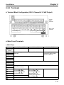
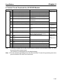
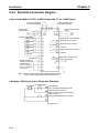
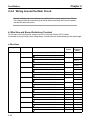
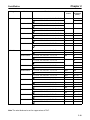
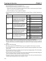
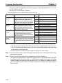
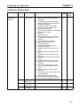
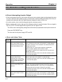
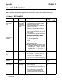
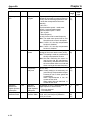
H Group 3: n050 to n108
Function
No.
Name
Reference
page
Description
Setting
range
1: 2.5 kHz
2: 5.0 kHz
3: 8.0 kHz
4: 10.0 kHz
5: 12.5 kHz
6: 15.0 kHz
7, 8, and 9: Varies in proportion to output
frequency up to 2.5 kHz.
10:7.0 kHz
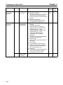
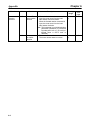
0: Inverter will discontinue running.
1: Inverter will continue running if power is
supplied again within instantaneous
power failure compensation time set
with n055.
2: Inverter will always continue running
without detecting UV1 or UV3.
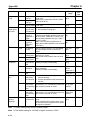
Set current level enabling speed search in
1% units based on rated output current of
Inverter as 100%.
Set time to start speed search after RUN
input is ON and instantaneous power failure processing starts.
1 to 10
(See
note 2)
3-80
0 to 2
[0]
3-81
0 to
200
[110]
0.5 to
10.0
(See
note)
0 to
100
(See
note)
0.0 to
2.0
(See
note)
3-82
0 to 10
[0]
0, 1 [0]
3-83
Carrier frequen- n050
cy adjustment
Carrier frequency
(See note 1)
Instantaneous
power failure
processing and
speed search
control
n051
Selection of
running after
restoration following a momentary stop
n052
Speed search
control level
n053
Minimum baseblock time
n054
V/f characteristics during
speed search
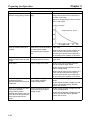
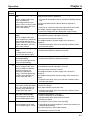
Set percentage of V/f characteristics for
speed search.
n055
Stop compensation time
Set instantaneous power failure compensation time in 1-s units.
n056
Number of error retries
Selection of error output during error retry
Set number of error retries.
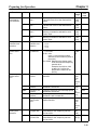
Jump frequency 1
Jump frequency 2
Jump frequency range
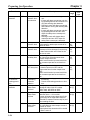
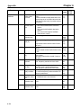
Set center value of jumping frequency in
1-Hz units.
Frequency jump function will be invalid if
value is set to 0.0.
0.0 to
400.0
[0.0]
3-83
Set jump range of jumping frequency in
1-Hz units.
0.0 to
25.5
[1.0]
3-84
Error retry
n057
Frequency
jump
n058
n059
n060
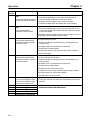
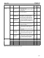
0: Turns ON error output while error retry
is performed.
1: Turns OFF error output while error retry
is performed.
3-82
3-82
3-82
3-83
3-84
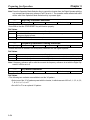
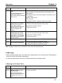
Note 1. For a 400-V Inverter, if the carrier frequency is set to a value higher than the default setting, the
Inverter overload “OL2” detection value will decrease in consideration of an increase in the
heat that will be generated by the change in the carrier frequency.
Note 2. Default settings vary with the Inverter model.
3-48