1
Chapter 3
Preparing for Operation
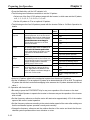
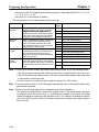
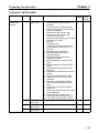
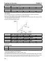
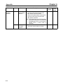
• Select with n079 whether to permit the Inverter to protect the Braking Resistor Unit connected to the
Inverter from overheating.
• The Inverter will display an error and turn OFF the output power when the Inverter detects the overheating of the Braking Resistor Unit with the RH signal if n079 is set to 1.
Set Values
Set value
Description
0
Inhibits overheating protection from functioning.
1
Permits overheating protection to function.
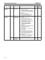
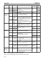
n080
Setting range
n081
Setting range
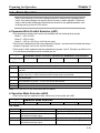
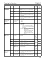
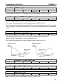
Input Open-phase Detection Level
1 to 100
Unit
(400/800 VDC
as 100%)
Default setting
7
Default setting
8
Input Open-phase Detection Time
2 to 255
Unit
x 1.28 s
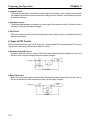
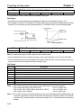
• The parameters n080 and n081 are used to set the input phase loss detection function.
• It is usually not necessary to change the default-set values.
• The Inverter will not detect input phase loss if n080 is set to 100.
• Set n080 of the 200-V Inverter based on 400 VDC as 100% and that of the Inverter of 400-V class
based on 800 VDC as 100%.
• The input phase loss detection function is used to detect the voltage ripples that will be generated from
the main circuit DC power supply when input phase loss results.
The Inverter will detect input phase loss if the voltage width of the voltage ripples of the main circuit DC
power supply exceeds the range set with n080 for a period exceeding the time set with n081.
• If the power supplied to the Inverter has ripples, set n080 or n081 to a large value so that the Inverter
will not detect input phase loss.
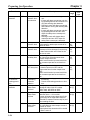
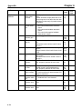
n082
Setting range
n083
Setting range
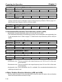
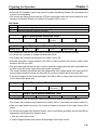
Output Open-phase Detection Level
0 to 100
Unit
% (Rated output Default setting
current ratio)
0
Output Open-phase Detection Time
0.0 to 2.0
Unit
s
Default setting
0.2
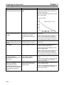
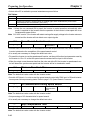
• The parameters n082 and n083 are used to set the output phase loss detection function.
• The Inverter will not detect output phase loss if n082 is set to 0. The default-set value of n082 is 0.
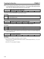
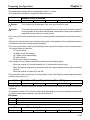
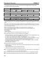
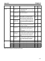
• When an output phase loss occurs, the Inverter will detect a decrease in the output current of the
phase.
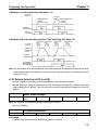
• To use the output phase loss detection function, refer to the following procedure and set with n082 an
appropriate output phase loss detection level.
1. Start the motor with no load.
2. Use the Digital Operator and monitor the amperage of the output current.
3-89