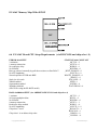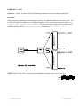
1
ISSUE Z / V
27T H NOVEMBER 2002
An Introduction To C
On The C166 Family
A Short Course In The Fundamentals Of
C166 Microcontroller Family Programming,
Application And Tools.
Hitex (UK) Ltd.
University of Warwick Science Park
Coventry, CV4 7EZ
Tel: 024 7669 2066
Fax: 024 7669 2131
[email protected]
http://www.hitex.co.uk
© Copyright
©
Hitex (UK) Ltd. 1997, 2002.
All Rights Reserved.
No Part of this publication may be transmitted, transcribed, stored in a retrieval system, translated into any
language, in any form, by any means without the written permission of Hitex (UK) Ltd.
Copyright Hitex (UK)
AllLtdtrademarks
1997
and registered names are acknowledged to be the property of their owners.
C166 Introduction Page 1
Contents
1. Overview ...............................................................................................................................................6
1.1 Course Introduction ..............................................................................................................................6
1.2 Basic Objective In C166 Programming .................................................................................................6
1.3 Course Schedule ..................................................................................................................................7
2. Setting Up The C166 Compiler System................................................................................................10
2.1 C166’s Environment Variables ...........................................................................................................10
2.2 Multiple Include File Search Paths ......................................................................................................10
3. Creating A New Project ....................................................................................................................... 11
3.1 Background Information On C166 Projects ........................................................................................ 11
3.1.1 Basic Data Types In C166 .............................................................................................................. 11
3.1.2 Basic Terms Used In C166 Programming .........................................................................................12
3.1.3 Memory Map Of EVA167 Board And Example Program.................................................................12
3.2 Setting Up The Directory Structure For The Example Project (Worked Solution) .................................13
3.2.1 Necessary Files To Build A Program................................................................................................13
3.2.2 Laying Out A C166 Program Module (Source File) ........................................................................15
3.2.3 L166 Linker Input Files ..................................................................................................................16
3.3 Creating A Project With The uVISION2 Workbench ..........................................................................16
3.3.1 uVISION2 Overview .....................................................................................................................16
3.3.2 Important uVISION2 Features .......................................................................................................17
3.3.3 Setting Up The Basic Project Structure ............................................................................................18
3.3.4 Setting The Tool Options .................................................................................................................20
The Target Tab Explained .........................................................................................................................20
3.3.4.1 The Listing Tab Explained ............................................................................................................21
3.3.4.2 The Output Tab Explained ...........................................................................................................21
3.3.4.3 The C166 Tab Explained ..............................................................................................................22
3.3.4.4 The A166 Tab ..............................................................................................................................26
3.3.4.5 The L166 Locate Tab ..................................................................................................................27
3.3.4.6 The L166 Misc Tab ......................................................................................................................28
3.4 Building New Projects For The First Time ...........................................................................................29
3.5 Making Use Of The Multiple Target Facility ........................................................................................29
3.6 The Special C167 Instructions ...........................................................................................................30
3.7 Register Masks And Global Register Optimization...............................................................................31
4. Using The HiTOP Monitor-Based Debugger .........................................................................................33
EXERCISE 0: EX0 ..................................................................................................................................34
5. Using uVISION And HiTOP In Program Development .........................................................................35
EXERCISE 1: EX1 ..................................................................................................................................35
6. Configuring The C Environment To Your CPU and Hardware ................................................................43
6.1 CPU-Specific Include Files ................................................................................................................43
6.2 Configuring STARTUP.A66 And START167.A66 .............................................................................44
6.2.1 Configuring STARTUP.A66 ............................................................................................................44
6.2.2 Configuring START167.A66...........................................................................................................46
© Copyright Hitex (UK) Ltd 1999
C166 Introduction
Page 2
6.2.3 Special Note On The CAN Pin Assignments On The C167CS .........................................................49
6.3 The Two Stacks In C166 ...................................................................................................................50
6.3.1 Setting The Size Of The User Stack ................................................................................................50
6.3.2 Advanced Technique - Placing The User Stack In On Chip RAM....................................................52
6.3.3 The System Stack ...........................................................................................................................53
6.4 Setting Up The BUSCONx ADDRSELx Registers ............................................................................54
6.5 Special Notes On The Startup Files ...................................................................................................56
6.6 EVA16C Board CPU Setup Requirements (via BUSCON0 and chip select 0) .................................57
EXERCISE 2: EX2 ..................................................................................................................................58
6.7 Configuring The Runtime Environment ................................................................................................59
6.7.1 Adapting printf() To Other Output Devices ......................................................................................59
6.7.2 Configuring scanf() For Other Devices ............................................................................................60
EXERCISE 3: EX3 .................................................................................................................................61
7. Inter-Module Linkage ..........................................................................................................................62
7.1 An Intelligent Include File Method That Will Avoid Many Program Build Errors ..................................62
8. The C166 Data Page-Addressing And Code Segmentation ..................................................................64
8.1 The Data Page Pointers .....................................................................................................................64
8.1.1 A Fast Way of Addressing a Large Data Memory Space .................................................................64
8.1.2 The DPPs expressed diagrammatically ............................................................................................64
8.1.3 Example Of Using DPPs .................................................................................................................65
8.2 Using The DPPs ................................................................................................................................65
EXERCISE 4: \EX4 ................................................................................................................................67
8.3 CODE "SEGMENTS" ......................................................................................................................68
8.4 DPP Usage Summary .........................................................................................................................68
9. C166 Compiler Memory Models .........................................................................................................69
9.1 Summary Of C166 Type Qualifiers That Determine Placement Of Data ..............................................70
9.1.1 Default Data Object Placement Overriding ......................................................................................70
9.1.2 C166’s Type Qualifiers Summary....................................................................................................71
9.2 Controlling Constant Data ..................................................................................................................73
EXERCISE 5: EX5 ..................................................................................................................................74
9.3 Setting Up The DPPs .........................................................................................................................74
9.3.1 Special Allocation Of DPP’s To Create Customised Memory Models ...............................................75
9.3.2 Special Memory Maps Possible With C166 v3.00 ...........................................................................76
9.4 Automatic Placement Of Data ............................................................................................................77
9.5 CLASSES And SECTIONS .............................................................................................................77
9.5.1 How Type Qualifiers Relate To Class Names In C166.....................................................................77
9.6 The Difference Between NDATA0 And NDATA ................................................................................78
9.6.1 The NOINIT #pragma ...................................................................................................................78
9.7 Modules And SECTIONs - Placing Things At Absolute Addresses ...................................................79
9.7.1 Special Note On Windows95 and NT4 ...........................................................................................81
9.8 Coping With The Special Sections "?C_CLRMEMSEC" And "?C_INITSEC". ..................................81
9.9 Placing Real Data At Fixed Addresses ...............................................................................................82
EXERCISE6: EX6 ...................................................................................................................................84
9.10 Using The RENAMECLASS Control ..............................................................................................85
9.11 SUMMARY OF PLACING OBJECTS AT FIXED ADDRESSES WITH THE LINKER: .............85
© Copyright Hitex (UK) Ltd 1997
C166 Introduction Page 3
EXERCISE 7: EX7 .................................................................................................................................86
9.12 THE ORDER PRAGMA .................................................................................................................86
9.13 The ASSIGN Linker Control ............................................................................................................87
9.14 The #pragma pack(1) Control..........................................................................................................87
9.15 Using "SECTIONS" With The C167CR CAN Peripheral..................................................................88
9.16 Constructing A Memory Map For Small C167CR Systems ..............................................................89
9.16.1 A Typical Small System Memory Map ...........................................................................................90
9.16.2 Constructing Linker Input File ........................................................................................................91
9.17 Relocating Functions Into RAM ........................................................................................................96
EXERCISE 9: EX9 ..................................................................................................................................98
EXERCISE 8: EX8 ...............................................................................................................................101
10. Non-ISO/ANSI Code Saving Tricks ................................................................................................102
EXERCISE 10: EX10 ............................................................................................................................102
10.1 Special Note On Bits In Structures .................................................................................................103
10.2 Bit Fields And Flags In C166.........................................................................................................103
10.3 Simple Bit Flags .............................................................................................................................104
10.4 The _testset_() And _testclear_() Intrinsic Functions .......................................................................105
EXERCISE 11: EX11 .............................................................................................................................105
10.5 Intrinsic Functions ..........................................................................................................................105
10.6 The volatile Keyword ....................................................................................................................107
11. Accessing Absolute Addresses ..........................................................................................................108
11.1 The MVAR and MARRAY Macros ...............................................................................................108
11.1.1 Things To Be Aware Of With This Method ..................................................................................108
EXERCISE 12: EX12 ............................................................................................................................109
12. Pointers In C166 ............................................................................................................................. 110
12.1.1 The Various Pointers In C166 ..................................................................................................... 110
12.1.2 Summary Of Pointer Declarations ................................................................................................ 110
12.1.3 Special Note On #pragma MOD167 For C167/5 Users ............................................................. 110
12.2 Variable Pointers To Absolute Addresses ....................................................................................... 111
12.3 Placing The Pointer Itself................................................................................................................ 112
EXERCISE 14: EX14 ............................................................................................................................ 113
12.4 Jumping To Variable Addresses...................................................................................................... 115
12.5 Pointer Casting And Conversions ................................................................................................... 115
12.6 Pointers To Local Data ................................................................................................................... 117
12.7 Addressing The C167CR CAN Peripheral Via Pointers .................................................................. 118
13. Using Peripherals With Zero Software Intervention ........................................................................... 119
EXERCISE 15: EX15 ............................................................................................................................120
14. The General Purpose Registers, Register Variables And Registerbanks...............................................121
14.1 The Context Switch .......................................................................................................................121
14.2 Interrupts In C166 .........................................................................................................................122
14.3 The VECTAB Linker Control ........................................................................................................123
14.4 Macros That Simplify The Setting Of Interrupt Priorities .................................................................123
EXERCISE 16: EX16 ............................................................................................................................125
EXERCISE 16 ( FOR C165: EX16 .165) ..............................................................................................127
© Copyright Hitex (UK) Ltd 1999
C166 Introduction
Page 4
14.4.1 Application Example - 32-Bit Captures ........................................................................................131
14.5 The Interrupt-Driven PEC System..................................................................................................132
14.5.1 Setting The PEC Channel Number ...............................................................................................132
14.5.2 Setting Up The PEC System ........................................................................................................133
14.5.3 Special C166 Language PEC Features Explained ........................................................................133
EXERCISE 17: EX17 ............................................................................................................................135
EXERCISE 18: EX18 ............................................................................................................................136
14.6 Switching Registerbanks In C.........................................................................................................137
14.6.1 The USING Control ...................................................................................................................137
14.6.2 Sharing Register Banks ...............................................................................................................137
EXERCISE 19: EX19 ............................................................................................................................138
EXERCISE 20: EX20 ............................................................................................................................140
14.7 When Your C166 CPU Keeps Flying Off Into Space... ................................................................141
14.7.1 The Trap.C File ...........................................................................................................................141
14.7.2 Common Reasons For Getting To Unexpected Traps ..................................................................142
14.7.3 New Control for Interrupt Functions ...........................................................................................142
14.8 Advanced Technique - Simulating Static Register Variables .............................................................142
14.9 Fixing Register Banks At Absolute Addresses ................................................................................144
14.10 Controlling the CP directly -Some Tricks With Registerbanks ....................................................144
14.11 Special Note On idata (classes IDATA0, IDATA) For C165/7 .....................................................145
14.12 Bit Addressable Data ...................................................................................................................146
14.12.1 Special Function Bits ................................................................................................................146
14.12.2 Note on declaring an sbit as external .........................................................................................146
15. Assembler Interfacing - In-line Assembler ........................................................................................147
15.1 Calling Assembler Functions From C166 ........................................................................................147
15.1.1 Coping With Start Addresses And Parameters .............................................................................147
15.1.2 Pointer Passing To Assembler Functions .......................................................................................149
15.2 Using C166 To Write Assembler Functions ....................................................................................149
16. The Part 2.0B CAN Module ...........................................................................................................151
16.1 CAN Registers ..............................................................................................................................151
16.1.1 Bit Time calculation.....................................................................................................................154
16.1.2 Resynchronization.......................................................................................................................155
16.2 Message Objects ...........................................................................................................................156
16.2.1 Using The SECTIONS Control To Access The C167CR CAN Peripheral ...................................159
16.3 Setting Up The CAN Module Baudrate And Sampling Point ...........................................................161
EXERCISE 30: EX30 ............................................................................................................................161
16.4 Configuring The CAN Module For Transmit ....................................................................................164
EXERCISE 31: EX31 ............................................................................................................................164
16.5 Configuring The CAN Module For Receive ....................................................................................168
EXERCISE 32: EX32 ............................................................................................................................168
16.6 Configuring The CAN Module For Remote Request .......................................................................170
EXERCISE 33: EX33 ............................................................................................................................170
16.7 CAN Module Bit Timing Calculation Spreadsheet ...........................................................................172
© Copyright Hitex (UK) Ltd 1997
C166 Introduction Page 5
1. Overview
1.1 Course Introduction
This course is intended as a basic introduction to C166 microcontroller programming. It will teach you the
basic skills and techniques required to produce efficient C166 programs and give you some ideas how the
powerful peripheral set can be employed. A learning-by-doing approach will be taken so that you will have a
chance to try new language features straight away. A working C167CR-based microcomputer is provided,
equipped with our HiTOP source level debugger with which programs can be tested. Many examples make
use of the C167's powerful and innovative peripheral set so that you will gain an appreciation of how they can
be applied in your own projects.
It is assumed that you are familiar with the fundamentals of the C language and have some experience of
assembler programming, preferably on the C166 family. We make no apologies for showing some of the
underlying assembler produced by the C166 compiler in those cases where misuse of compilation controls can
cause program problems.
Each language feature is covered by a programming exercise. You have the choice of creating the program
from the specification given or using the “shell” modules, which have the basic framework of the required
program already mapped out. You will find complete working versions in the SOLUTION subdirectories
from which you can take ideas, or use as is! The outlines of the examples can be found the WORK subdirectories for you to complete.
The content is based on the most common questions asked by C166 users and our own experience of what
really counts in C166 programming. It is unlikely that you will remember everything once you start using
C166 for real but what you will find is that you’ll be able to refer back to the notes should anything difficult
crop up. You will not end the course as a C166 expert but you will be in a position to start a major development, armed with the basic knowledge to ensure its success.
We will use the Keil uVISION Windows integrated development environment as the means of creating and
compiling the exercises and HiTOP to debug them. The built-in uVision editor is an entirely main-stream
Windows programming editor, with automatic error and syntax highlighting and should be familiar to anybody
who has used a Windows word processor, Codewright or PFE. Hitex's HiTOP is a flexible source-level
debugger for the C166 family, being used here in its monitor version.
1.2 Basic Objective In C166 Programming
To acheive the fastest possible execution by using only the C language, leading to...
=> Fastest system response to real time events
=> simpler, more maintainable code
=> cheaper EPROMs & RAMs
=> smaller bus width.
=> lowest system cost
© Copyright Hitex (UK) Ltd 1999
C166 Introduction
Page 6
1.3 Course Schedule
The course will run in approximately the following order:
Course introduction
Aims of course
Equipment and resources provided
An overview of the Siemens C166 microcontroller architecture
CPU design
Peripheral set
Memory map(s)
Setting up the compiler system
Basic concepts and procedures to be understood before using the tools
Creating a project
The uVISION “Project” manager
Basic terminology used in C166 programming
Fundamental compiler controls
Components of a C166 program
Using the HiTOP debugger
A quick driving lesson in Hitex’s HiTOP
Exercise EX0: Construct a project from supplied software components, to run on EVA16C
development board.
Exercise EX1: Practice using the controls and features of uVISION and HiTOP with an
example program.
Adapting the ANSI C language to the C167 hardware
CPU-specific include files
Configuring the C167 bus interface in START167.A66
Exercise EX2: Modify START167.A66 to set up user stack, system stack and BUSCON1 to suit
EVA167 hardware.
Global register optimization
The two C167 stacks
Redirecting formatted IO (printf() scanf()) etc.
Exercise EX3: Redirect redirect print() to LCD display to print a seconds counter to the LCD.
Constructing C166 programs
The “include file” method
© Copyright Hitex (UK) Ltd 1997
C166 Introduction Page 7
Understanding the internal structure of the C166 core
Expediting data accesses via DPPs (Data-Page Pointers)
Exercise EX4: Working out physical addresses from DPP and EXTS examples
Special C keywords for different C167 memory areas
C166 Compiler memory models and memory management
Methods for putting specific code and data items at appropriate addresses
Linker controls and keywords
CLASSes and SECTIONs
Exercise EX5: Pitfalls when creating pointers to constant objects!
Customising memory models for efficiency
Coping with non-volatile RAM and memory-mapped IO devices
Exercise EX6: Using the NOINIT and SECTIONS control to address memory-mapped IO
Exercise EX7: Using the NOINIT and RENAMECLASS control to address memory-mapped IO
Typical memory maps for small, high performance systems
Exercise EX8: Constructing a linker control file for a typical C167 system
Exercise EX9: Relocating functions into idata for execution - checksumming ROMs
Non-ANSI code saving tricks and ideas
Squeezing extra performance from C by using assembly-programming tricks!
C pointers in C166
How C’s pointer types are adapted to the C166 architecture
Accessing fixed addresses
Exercise EX12: Use the “HVAR” macro to access a memory-mapped DIL switch on chip select 4
and print value to LCD display.
Obscure embedded C problems - placing the pointer itself
Using variable address pointers for real programming tasks
Exercise EX14: Perform a memory test over the RAM from 0x50000 to 0x5FFFF and print results
to LCD display.
Using C167 Peripherals In C
Using peripherals to perform tasks with near-zero software intervention
© Copyright Hitex (UK) Ltd 1999
C166 Introduction
Page 8
Exercise EX15: Configure general purpose timer block 1 (GPT1) to measure speed and direction
of quadrature-encoded input.
Interrupts in C166 - the 100ns context switch
Interrupt sources – the CAPture And COMpare (CAPCOM) unit
Exercise EX16: Make a 16-bit period & frequency measurement of square wave on P2.3 using
the CAPCOM unit or optionally with the GPT1 timer2 on P3.7 (C165 users)
Exercise EX16A: Generating a periodic waveform with the CAPCOM unit on P2.15 or or
optionally on P3.3 with the GPT1 timers 3 & 4 (C165 users)
Using the peripheral event controller (PEC) to reduce CPU loading with repetitive tasks.
Exercise EX17: Use the PEC to buffer continuous A/D readings into RAM buffers every 9.7us.
Exercise EX18: Receive a 4800 baud serial bit stream on P2.3 to reconstruct a message using the
CAPCOM unit and timer 3/2.
Exercise EX19: Receive a 4800 baud serial bit stream on P2.3 to reconstruct a message using
just the CAPCOM unit to reduce CPU overhead.
Using the C167 in Controller Area Networks (CAN) - Optional Topic
Basic CAN concepts
Calculating the bit timing parameters
Choosing the bit timing values
Exercise EX30: Calculate the bit timing register values for 100kbit/s and 75% sampling point.
Transmitting messages across CAN
Exercise EX31: Transmit the value on potentiometer zero on the 167IO board to the tutor’s CAN
monitoring program, using the supplied message ID..
Receiving messages across CAN
Exercise EX32: Receive the values of the pots. On three neighbouring stations and use them to
control the bightness of three LEDs on the 167IO board.
Using the Remote Request Mode
Exercise EX33: Use the remote request mode to obtain any one of four short messages string from
the tutor’s node. This is a race!
Course Wrap-Up And Questions
Points arising from material covered.
© Copyright Hitex (UK) Ltd 1997
C166 Introduction Page 9
2. Setting Up The C166 Compiler System
There are a number of basic settings that must be made to allow the compiler to run correctly.
2.1 C166’s Environment Variables
To help C166 find its include and library files, make sure that the \AUTOEXEC.BAT file on your PC contains
the following:
PATH=C:\KEIL\C166\BIN;%PATH%
SET C166INC=C:\KEIL\C166\INC
SET C166LIB=C:\KEIL\C166\LIB
SET TMP=C:\TEMP
Special Note On SET C166INC=
(i) Any include file given thus:
#include <reg167.h>
will be searched for firstly in the current and directory and if not found, in the directories indicated by the SET
C166INC= <PATHNAME>
2.2 Multiple Include File Search Paths
The SET:
SET C166INC=C:\KEIL\C166\INC;C:\166TRAIN\HEADERS
will cause C166 to search the \166TRAIN\HEADERS directory as well. Make sure that the
AUTOEXEC.BAT contains this as well.
(i) In a C source file, if you enclose the include file name in quotes;
#include “reg167.h”
then only the current directory will be searched. If the include file cannot be found, C166 will report an error.
© Copyright Hitex (UK) Ltd 1999
C166 Introduction
Page 10
3. Creating A New Project
uVISION operates on the basis of “Projects” where all the source files and compiler and linker options are
stored in a “.UV2” file. This file is thus an important part of the software development process and must be
archived with the source files and C166 compiler version used. The name of the project is left to the user
but in the examples, the project name is based on the exercise name so that EXERCISE0 will use a project
called EX0.UV2, EXERCISE1 will use a project called EX1.UV2 and so on.
To explain how the uVISION system is used and how a simple program can be constructed within it, the
necessary steps will be run through in sequence, with enough detail to proceed to the next stage. This will
form the basis of the first exercise, in \166TRAIN\EX0\SOLUTION.
3.1 Background Information On C166 Projects
3.1.1 Basic Data Types In C166
The data types available are:
bit
char
unsigned
int
short
unsigned
unsigned
long
unsigned
float
double
pointer
=
=
char
=
=
=
int
=
short =
=
long
=
=
=
=
1-bit
0 - 1
8-bits
0 - +/- 127
8-bits
0 - 255
16-bits
0 - +/-32768
16-bits
0 - +/-32768
16-bits
0 - 65535
16-bits
0 - 65535
32-bits
0 - +/- 2.147483648x10⁹
32-bits
0 - 4.29496795x10⁹
32-bits
+/-1.176E-38 to +/-3.4E+38
64-bits
+/- 1.7E-308 to +/- 1.7E+308
16/32-bits Variable address
Notes:
- The 16-bit ANSI “short” type equates exactly to int. The latter takes the “natural” size of the CPU,
here 16-bits.
- The machine size of the C166 is 16-bits hence int, short or unsigned int, unsigned short should be
used when possible to produce the most compact and efficient code. The use of char and unsigned
char will result in a lot of MOVBZ-type instructions which waste time.
- char and unsigned char: Unless you explicitly want a signed 8-bit number, always use unsigned char.
Char is normally reserved for ASCII characters which have no sign.
Thus:
/*** Define an 8-bit number ***/
unsigned char byte_var ;
/*** Define a character string **/
char ASCII_string[] = { “Guten Tag” } ;
© Copyright Hitex (UK) Ltd 1997
C166 Introduction Page 11
As the strcpy, strcat and other string functions all assume “char”, you will get warnings if you try to
manipulate “unsigned char” objects with them.
3.1.2 Basic Terms Used In C166 Programming
Unfortunately, some terms will have to be used to describe how to build the example program which as yet
have not properly been defined. They will of course be fully explained later in the text. For now, here are
some simplified definitions of terms used which will help you to understand roughly what is going on!
Compiler-Related Terms
IDATA
NEAR
FAR
Registers
R1, R2 etc.
User Stack
System Stack
DPP0,1,2 & 3
Memory Model
= On-chip RAM at 0xFA00 (C166) or 0xF600 (C167/5)
= Area of off-chip RAM whose variables can be accessed in one instruction
(medium to fast speed access)
= Area of off-chip RAM whose variables require several instructions to
access (slow access)
= Bank of 16 general purpose word registers used for local (automatic)
variables,function parameters, intermediate calculation results. (Fastest
access of all)
= Register within the current register bank
= Artificial stack created by C166 to hold some local variables. Formed
from MOV Rw, [R0+] type instructions. (Slow access)
= C16x’s own proper hardware stack in on-chip RAM with which PUSH and POP
instructions can be used and onto which return addresses are placed during
subroutine calls.
= Registers which hold the base addresses of regions in multiples of 0x4000
(16k), each of which is 0x4000 bytes long. For example, DPP3 always
equals 3, indicating a 16kb region from 3 * 0x4000, i.e. 0xC000 to 0xFFFF.
= How the compiler decides to place its variables, i.e. on-chip or off-chip,
fast or slow access
Linker-Related Terms
CLASSES
SECTIONS
VECTAB
REGBANK
RESERVE
CINITAB
= Locates the named large date or code items at the stated address
= Locates the code or data from a single source file (module) at the stated
address
= Sets the base address of interrupt vector table area.
= Locates the named registerbank at the stated address.
= Prevents any code or data object in the stated address range.
= Locates the variable initialisation tables in ROM
3.1.3 Memory Map Of EVA167 Board And Example Program
Monitor EPROMS:
On-chip XRAM RAM:
On-chip IDATA RAM:
Off-chip RAM:
0x00000
0x0E000
0x0F600
0x40000
-
0x1FFFF
0x0E7FF
0x0FDFF
0x5FFFF
NOT AVAILABLE
The off-chip RAM is notionally split into two ranges: 0x40000 - 0x4FFFF is treated as an EPROM area for
code and constants and 0x50000 - 0x5FFFF is used as a RAM area.
Off chip RAM allocation:
Your interrupt vectors:
Monitor’s RAM:
Your program starts at:
Your program ends at:
Your off-chip RAM:
© Copyright Hitex (UK) Ltd 1999
0x40000 - 0x403FF
0x40400 - 0x41FFF
0x42000
0x4FFFF
0x50000 - 0x5FFFF
NOT AVAILABLE
C166 Introduction
Page 12
3.2 Setting Up The Directory Structure For The Example Project (Worked Solution)
3.2.1 Necessary Files To Build A Program
The basic files required to build a working C166 application are:
(i) Source files containing executable C statements
Extension: .C
(ii) Header files containing function prototypes and definitions
Extension: .H
(iii) An optional linker input file containing a list of object files and linker controls
Extension: .LIN
In exercise EX0 we will use uVISION to control the linker although in a real project a linker control file
would be used.
(iv) A project control file containing the list of source files in the project and the compiler controls etc.:
Extension: .UV2
C166 will emit the following files types:
.OBJ - Unlocated object file with no absolute addresses assigned.
.LST - A list file containing the original source lines but with any errors or warnings
indicated
.SRC - An optional file containing the assembler code generated by the compilation process.
This can be assembled with A166 to produce the .OBJ file as an alternative to going
straight to a .OBJ file from the compiler.
.ERR - A summary of the errors and warnings that occurred during compilation
The L166 linker will emit the following files:
.<noextension> - Absolute object file in the Siemens extended OMF66 format, containing a
binary representation of the program plus optionally, debug symbol information. It also
holds the necessary make information to allow uVISION to rebuild the program.
.M66 - A map file containing the address and length of all classes, sections and
registerbanks.
.REG - A special file which holds information on all the registermasks generated by every
function in the program. By giving this file back to the compiler, it can be used to allow
global register usage optimisation.
.LNK - A linker control file automatically generated by uVISION which contains the user’s own
.LIN linker control file with the object file list prepended to it.
© Copyright Hitex (UK) Ltd 1997
C166 Introduction Page 13
It is assumed that the various files that constitute the project will be arranged within and off a root
directory of:
\166TRAIN\EX0\SOLUTION
In the following, this will be referred to as the project “ROOT” directory.
While all files could be placed in the root directory of the project and uVISION left to show only those files
which are appropriate, it is neater to make sub-directories for the different types of file within the project:
ROOT
ASM
INC
MISC
SRC
Object files, EXEC.PRJ project file, EXEC.LIN linker file
Assembler source files
Include files (.h)
Control file for SP166KE symbol processor
C source files (.C)
In the completed example project, the following files can be found in each sub-directory:
ROOT EXEC.PRJ: Project control file
EXEC.REG: Global register optimisation file
EXEC.LIN: Linker control file
EXEC.LNK: EXEC.LIN with object file list added automatically by uVISION
EXEC.LER: Linker error report file created by uVISION
EXEC.M66: MAP file showing location of every program object
EXEC:
Absolute OMF66 executable file
EXEC.HTX: Code binary file for HITOP166/WIN
EXEC.SYM: Symbol database file for HITOP166/WIN
START167.OBJ, MAIN.OBJ, PUTCHAR.OBJ, SOFTUART.OBJ object files
\ASM START167.A66 assembler source file
\INC SOFTUART.H, INTMAC.H header files
\MISC SFR_167.CTL C167 SFR definitions file for SP166KE.EXE symbol processor
\SRC MAIN.C, PUTCHAR.C, SOFTUART.C, MAIN.LST, PUTCHAR.LST,SOFTUART.LST
The project directory should contain the following sub-directory structure from
\166TRAIN\EX0\SOLUTION:
© Copyright Hitex (UK) Ltd 1999
C166 Introduction
Page 14
3.2.2 Laying Out A C166 Program Module (Source File)
Here is how we suggest you layout your C166 modules. You can find a ready made “empty” MAIN.C in
\166TRAIN\USEFUL although there is a suitable one in the EX0 directory already.
Sample MAIN.C
#pragma SMALL
#pragma MOD167
/* Compiler controls */
/*** CPU Specific Includes ***/
#include <reg167.h>
/*** ANSI Library Includes ***/
#include <stdio.h>
/*** Module Specific Includes ***/
// not used yet!
/*** Global Data Declarations ***/
/*** Function Prototypes ***/
void main(void) ;
/*** Executable Functions ***/
void main(void) {
}
// Enter here from reset
This is compiled with:
C166 MAIN.C DEBUG SMALL REGFILE(EXEC.REG) WL(2)
Or:
with the uVISION Project-Compile File command.
© Copyright Hitex (UK) Ltd 1997
C166 Introduction Page 15
3.2.3 L166 Linker Input Files
Although it is possible to drive L166 directly from the command line, this can get very tiresome on real programs. L166 is able to take its input from a text file which usually has the same file name stem as the executable but with the extension “.LIN”. Here is a sample one:
EXEC.LIN:
VECTAB(0x40000)
CLASSES(NCODE(0x40400),NCONST(0x40400),NDATA(0x48000))
SECTIONS(?C_CLRMEMSECSTART(0x40400),?C_INITSEC)
REGFILE(exec.reg)
This is invoked with:
L166 @EXEC.LIN
Or: with the uVISION Project-Build command.
3.3 Creating A Project With The uVISION2 Workbench
3.3.1 uVISION2 Overview
uVISION2 provides an industry-standard Windows interface to the Keil C166 compiler and linker tools. It
is reasonably straightforward to configure and can support large program developments. Its user interface is
split into special windows, as shown below:
TARGET SELECTOR
TOOLBAR
EDITING AREA
PROJECT FILE
LIST
OUTPUT WINDOW
© Copyright Hitex (UK) Ltd 1999
C166 Introduction
Page 16
uVISION2 considers C166 programs as "PROJECTS" which can be built in different ways to suit different
"TARGETS" - in a real development, you may have a set of source files that are compiled with different
controls for different hardware platforms, that may also require different memory maps. For example, in the
training exercises, we will be building programs for a "MONITOR" target that has the code offset by
0x40000, as required by the HiTOP debugger (in this guise). For such a program to run directly from
EPROM on the board, a second target is used which differs only in that is has the code at zero.
3.3.2 Important uVISION2 Features
The Toolbar Functions
Target Options Wizard
Compiler And CPU
Documentation
Select The Target Type
Most uVISION functions can be
accessed from the toolbar. We will use
uVISION2 to produce the all the
example programs, as will be explained in the next few sections.
Project File Details
© Copyright Hitex (UK) Ltd 1997
C166 Introduction Page 17
3.3.3 Setting Up The Basic Project Structure
With uVISION already running...
- Select Project-New and navigate to
\166TRAIN\EX0\WORK. Enter the project name
"EX0" in the dialog box.
- Enter the main project sub-directory and type in the
project name, here “EX0.UV2”. The UV2 file is
equivalent to the MAKEFILE in a conventional system. It contains all the make, assembler, compiler and
linker options entered from uVISION’s Options menu.
It therefore has a major influence on how the program
is constructed and must be archived along with all the
source files. Click "OK" to exit.
Next uVISION needs to be told which CPU the program will be built for - the "Select Device For Target
1" dialog box will appear automatically. Select the
Infineon (formerly Siemens) C167CR-LM device
from the CPU list.
uVISION allows a number of TARGETs to be defined. The C167
hardware platform to be used here will running a monitor debugger so
a TARGET called "monitor" will be created. Select the "Targets,
Groups, Files" item on the Project menu. Add the target name "monitor" in the top dialog box and click "Add". Click on the existing target
TARGET1 and click "Remove Target" as this target is no longer
required- "monitor " will now become the current target. Exit the
menu with "OK".
uVISION allows files of similar types to be collected togther in
"Groups". In the project, all the C source files will be in the existing "Source Group1" group whilst the START167.A66 assemblercoded start-up file will be in a new group "Config". From the
Project menu, select the Groups/Add Files tab and enter "config" in
the dialog box. You should end up with two groups , "Source
Group 1"and "config" to which we will later add program source
files.
© Copyright Hitex (UK) Ltd 1999
C166 Introduction
Page 18
The source files that constitute the project are added by selecting first
Source Group 1 and right-clicking and then choosing "Add Files To
Group "Source Group 1".
The C source files for Source Group 1 are added by
entering the directory "SRC" and double clicking on
the required source files. In the example, all source
files are needed. Use "Close" to end the task.
A similar process is required to add the single
.A66assembler file to the "config" group. Right click the
config group and select add files to group 'config'.
Double click START167.A66 and then "Close".
To enable uVISION to find the compiler executable plus header files and libraries, the
Project-Environment Setup menu must be
completed. This is similar to a MS-DOS set
up that might be entered in AUTOEXE.BAT if
the compiler was to be used from a MAKE
utility or batch files.
The example uses a header file (INTMAC.H) located in C:\166TRAIN\HEADERS so this path must be
added after a semicolon delimiter in the "INC Folder" box.
Hint: If you get a warning along the lines of “Error during parsing Line: #pragma...” then suspect that
this menu has not been properly configured.
Note that you must have previously created a C:\TEMP directory - failure to do so could
result in “Out of Workspace “ warnings when compiling.
© Copyright Hitex (UK) Ltd 1997
C166 Introduction Page 19
3.3.4 Setting The Tool Options
The compiler, assembler and linker options are
set through the "OPTIONS" wizard, located at the
top right of the screen.
. The Options for
target menu is split into eight sections that are
selectable from the tabs at the top of the panel.
Each target specified in the project has its own
target options.
- Although not strictly necessary, the XRAM at
0xE000 and the C167CR CAN module are enabled by ticking the "Use On-chip CAN+XRAM"
box.
- Data should be set to "idata 6" so that the compiler will place all data objects of up to 6 bytes in
length will be placed into the on-chip idata area
at 0xF600. This is a way of making sure that
large objects such as arrays and structures do not
eat up valuable fast on-chip RAM.
The Target Tab Explained
- Enter the Clock speed as 20MHz. The actual
oscillator frequency is 5MHz but the C167CR
has an internal PLL that multiplies this by 4.
- The Memory Model is" HLarge", the preferred
model for the majority of C167 programs. The
Memory model determines how the compiler
will allocate program to different data areas.
The choice of memory model is explained in
chapter 9.
- Operating System is" none" in this example
© Copyright Hitex (UK) Ltd 1999
- The Near Memory boxes are an advanced
feature and should be left at 16KB RAM and
16KB ROM. Their real purpose will be explained later!
- The External Memory boxes allow you to
specify where the ROM and RAM areas are in the
hardware. For the EVA16C board used in the
example, the user's CODE area starts at 0x42000
and is of length 0xE000 bytes. Use the down
arrow on the "#1" box ans selct ROM. The
user's RAM area is from 0x50000 of size 0x10000
and these addresses should be entered in the #2
box.
C166 Introduction
Page 20
3.3.4.1 The Listing Tab Explained
Here the most useful option is the Generate .LST File after compilation. This will contain the original source
file with any errors or warnings indicated where they occured. The “Include Symbols” option is useful as it
will list all the function and variable names, along with their type information at the base of list file.
3.3.4.2 The Output Tab Explained
This menu specifies the output file names and allows the HiTOP symbol processor to be included in the build
process and a HEXfile to be emitted for FLASH programming.
- In the example,the Name of executable is EX0 and it will be placed into the ..\OBJ directory through the
Select Folder fo Objects... button.
- The HiTOP debugger requires Debug information
- uVISION includes a browser function which is enabled via Browse Information
- After the make process has completed, a Beep When Complete can be specified
- The HiTOP debugger requires a special symbol utility to be run which converts the EX0 output file in the
OMF66 format into the .HTX format. This requires Run User Program #1 to be ticked and the line:
sp166ke obj\ex0 -v -s\166train\ex0\work\src -s\166train\ex0\work\asm
to be added in the dialog box. The -s option allows the full pathname of the source files to be passed to the
utility so that HiTOP can give source level debugging.
© Copyright Hitex (UK) Ltd 1997
C166 Introduction Page 21
3.3.4.3 The C166 Tab Explained
There are three ways of controlling how the C166 compiler and A166 assembler translate a particular source
file:
(i) Via the command line:
C166 MAIN.C DEBUG MOD167 HLARGE
(ii) Via the #pragma keyword:
#pragma MOD167
#pragma HLARGE
#pragma DEBUG
(iii) Via uVISION’s Options-C166 Compiler... menu item, covered in detail later.
In anything but the smallest of projects, method (i) is not suitable. In practice, it is sometimes used just to
quickly compile something from the MS-DOS command line with an unusual control such as “SRC”, which
produces a valid assembler/C mixed file. This “.SRC” file can be useful for assessing code quality or for
interfacing to assembler-coded functions.
Usually, a combination of (ii) and (iii) is used. However, the user must decide which controls should be
supplied by uVISION and which should be embedded in the source by the #pragma keyword. Where the
default compiler setting is acceptable, it is not really necessary to explicitly state the control. As a general rule,
anything which can alter the generated code must be given by a #pragma: although uVISION is unlikely to
lose or alter a control over the duration of a project, bitter experience has shown that just prior to release,
something will go astray and some vital control will disappear, resulting in a subtle change to the code. This
will invalidate any proving work which has been done and may well result in unexpected program behaviour.
Therefore you should not rely on an external tool (i.e. uVISION) to set the really important controls!
If you are using a conventional command-line approach with an external MAKE utility, then the same rules
apply in that your makefile should ideally not supply the “hard controls”. In all cases, it is acceptable to place
the really critical controls in a header file, usually named “PRAGMAS.H” which contain them.
Even if you do not intend to use uVISION, it does provide a quick way of putting togther the control keywords you require as it displays the final command line in the “Compiler Control String” box. The resulting
string can then be used to construct the individual #pragma control lines in your source files - in effect,
uVISION acts like an interactive user manual!
Here are some tips as to where to put the controls in a real project:
(i) Compiler Hardwired “HARD CONTROLS”
Generally anything which can influence the code generator or optimizer - here are a few of the most common:
MOD167
SMALL
NODPPSAVE
OPTIMIZE(x)
-
© Copyright Hitex (UK) Ltd 1999
Enable C167 family code generator
Set the memory model
Do not stack DPP3 on entry to interrupt routines (C167 only)
Bias the code generator towards optimum program SIZE or SPEED
C166 Introduction
Page 22
WARNINGLEVEL(x) STATIC
ORDER
-
FLOAT64
-
Check for C language use and abuse
Put locals which overflow the available registers into statically
allocated memory segments rather than using the user stack.
Place variables in RAM and constants in EPROM in the order in which they
appear in the source file
Enable the “double” 64 bit float type and use double precision floating
point for all trigonometric and transcendental mathematics library
functions.
Note: Other controls exist which can influence the final code such as RENAMECLASS and NOINIT but
as these require a detailed understanding of the structure of a C166 system to use, they will not be covered
until later in the course.
(ii) uVISION Compiler “SOFT CONTROLS”
DEBUG
SRC
LISTINCLUDE
SYMBOLS
-
Enable symbol information for debuggers
Produce an assemblable equivalent of C source file
Expand include files out within .LST file
Place listing of module’s symbols in the listing file
Here, the options appropriate for the training examples will be given. However these will probably be
suitable for your own projects as well. The settings given in the following will be needed in exercise
EX0 to illustrate the compilation and linking of the example program in \166TRAIN\EX0\WORK.
Whilst most of the controls are best given via #pragma, you can still state them in the uVISION C166
compiler options menu. If the controls supplied via the two routes do not match, you will get a “CONFLICTING CONTROL” warning.
- Save DPP on interrupt s optimises interrupt service routines: on the C167, DPP3 is always set to 3 to
indicate the base of the SYSTEM area at 0xC000 and DPP0 is never changed from its power-up value,
unless the user alters it himself. Therefore, C166 need not stack these two registers on entry to an interrupt
routine, thereby saving two PUSHes and POPs (0.4us @20MHz).
© Copyright Hitex (UK) Ltd 1997
C166 Introduction Page 23
Alias checking on pointer access is an advanced option which can acheive a small code saving on pointer
operations. The NOALIAS control can cause unexpected results in when global or static objects are modified by pointers. In most cases source code that could be upset by this control does not conform to the
MISRA-C guidelines and should therefore not be present anyway. It is recommended that this control is not
used.
Example
Without NOALIAS
struct { int i1; inti2; } *p_struct ;
int val ;
void func1(int *p_val) {
p_struct->i1 = val ;
*p_val = 0 ;
p_struct->i2 = val ;
}
// Read val
// Zero val via pointer
// Read val again. Now it is zero
void func2(void) {
func1(&val) ;
}
With NOALIAS
struct { int i1; inti2; } *p_struct ;
int val ;
void func1(int *p_val) {
p_struct->i1 = val ;
*p_val = 0 ;
p_struct->i2 = val ;
}
//
//
//
//
Read val
Zero val via pointer
Read val again. Value from first read carried forward
so zeroing by pointer in previous line is not seen
void func2(void) {
func1(&val) ;
}
Use static memory for non-register automatics influences how the compiler treats local variables (automatics). Normally C166 will try to put as many local variables into registers (R1-R15) as possible as the
MOV Rw,Rw register-to-register instructions execute in 100ns (@20MHz). All the normal ADD, SUB,
CMP type instructions are available in the register-to-register variety so that any such operation will take just
100ns. Variables that overflow the available local registers are placed on the “User Stack”, as in a PC-type
compiler and are addressed via MOV R1,[R0 + #displacement] type instructions. As a RISC CPU, there
are few “stack-relative” instructions so that operating on user stack variables usually takes several instructions.
A significant performance advantage for interrupt functions or those with a large number of local variables can
therefore be had by forcing the compiler to put locals that cannot fit into registers (R1-R15) into (near) static
RAM segments to create a “compiled” stack, as in the C51 compiler. The common ADD, SUB and CMP
instructions all can operate directly on RAM so that there is little performance loss when compared to
reegister variables.
Note that any functions within modules compiled with this control will no longer be reentrant, thus if enabled
here in the C166 Options menu, no reentrancy will be possible across the entire program which may not be
© Copyright Hitex (UK) Ltd 1999
C166 Introduction
Page 24
acceptable. This control is therefore better used as a #pragma STATIC with only those modules which
contain functions which can be used non-reentrantly, such as interrupt routines.
Whilst not essential, the compiler can be forced to make sure that variables are placed in memory in the
order in which they appear in the C source file via the Keep variables in order option. This can sometimes result in wasted RAM as words (short and int types) cannot be placed on odd addresses by the
L166 linker, resulting in odd bytes being left unused. In most situations, this control (a.k.a. #pragma
ORDER) is best used within a source file whose data must be at a defined address - see section 9.12 for
more details.
The Code Optimisation level is best left at maximum, the default which also means that C166 will try to
generate the fastest possible code, even if it means increasing code size somewhat. Examples of where the
Emphasis option has some effect is in switch() statements where the compiler will produce either a fast but
bulky jump table to the case statements, or use a compact but slower “target address calculation” approach.
Double Precision Floating point may be required if you are using floating point numbers, the double
keyword is actually treated as float by default, i.e. single precision (7 significant figures). To make the double
type into a true double precision (13 significant figures) quantity, select this option. Float will remain as single
precision but sin(), cos() log() etc. library functions will all become double precision.
Application Note:
Typical Execution Times (20MHz CPU clock)
(i) Single Precision Floating Point
divide = 9-11us approx
sin(x) function = 184-280us
(ii) Double Precision Floating Point
divide = 13-16us approx
sin(x) function = 220-340us
Treat char as unsigned will force the compiler to do as its name implies. By default, C166 treats the “char”
type as a signed 8-bit quantity. Source code which originated from another compiler may assume that char is
unsigned.
- Global Register Coloring is an optimisation that allows the Linker to recompile any source files which
could have their register usage optimised using a different “register mask”. This is an iterative process
whereby the linker makes up to nine compile-link-optimize-compile attempts to make the best allocation of
general purpose registers (R1 - R15) between nested functions. For the purposes of the exercises, leave the
Global Register Coloring item disabled. As this feature extends the compile-link time considerably and is
only really useful on larger programs, it is best left in the off state for the example program.
The Warnings level is set to “Level 2: detailed” by default so that an almost PC-lint type capability is enabled within C166. Do not be tempted to turn the warning level down as it will be possible to produce unsafe
code which is however legal C, especially where pointer use (and misuse) is concerned You have been
warned!
© Copyright Hitex (UK) Ltd 1997
C166 Introduction Page 25
Tip: If you want to discard any changes you have made, click the Default button to restore the original settings.
- Define box allows any #defines to be passed to the compiler from the command line.
Example Of External #define:
#ifdef _OPTION_A_
clock_speed = 16 ;
#else
clock_speed = 20 ;
#endif
// This is set from outside source file by uVISION
None are required in the example program!
Misc Controls box can be used to hold any special controls that will not be used in the main program
development such as the SRC option. This is usually only used to quickly see what assembler code the
compiler has produced during development of critical code sections. It must usually be removed before the
next full build is performed.
Advanced note: By right clicking on individual source files, the compiler options for a single file can be set.
3.3.4.4 The A166 Tab
The A166 assembler is set up in much the same way as the compiler. However there are no special controls
required for almost all C166 programs. However, in programs built without uVISION it is important that the
assembler knows which memory model the compiler is using and that a C167 CPU is the target . The
"HLARGE” in the A166 command line SET() control does this. Whilst the START167 source file contains
a $SEGMENTED control, it is sensible to enable it here with the SEGMENTED control. If this control is not
present, the assembler will only be able to produce programs which can run in the non-segmented CPU
mode which means a memory space limit of just 64K.The complete A166 command line would be:
MOD167 SET (HLARGE) DEBUG.
© Copyright Hitex (UK) Ltd 1999
C166 Introduction
Page 26
3.3.4.5 The L166 Locate Tab
The L166 linker is set up in much the same way as the compiler. However, experience has shown that the
nature of the controls necessary for the linker in a real project are best placed in a conventional ASCII text
file, here named EX0.LIN. This contains only the controls necessary to locate the program at the correct
addresses, i.e. the CODE in the EPROM and the DATA in the RAM!
EXEC.LIN From Example Program
// Linker Input File For The HLARGE Model
//
// Shift user's interrupt vectors (inc. reset) to 0x40000
vectab(040000h)
// Prevent User's Program Using Monitor's RAM
reserve(0f200h-0f5ffh)
// Move user's C main registerbank above monitor's
REGBANK(0fd00h)
// Fix classes for HLARGE model in free RAM
CLASSES(ICODE(042000H),
FCODE(044200H),
NCONST(044200H-047FFFH),
HCONST(044200H),
NDATA(050000H-053FFFH),
NDATA0(050000H-053FFFH),
FDATA(050000H),
FDATA0(050000H),
HDATA(050000H),
HDATA0(050000H),
XDATA(050000H),
XDATA0(050000H))
// Put startup code sections into free RAM
CINITAB(44200h)
However for the example we will let the Target Tab's ROM and RAM boxes provide the necessary
location information instead of an external .LIN control file , i.e. where the ROM and RAM are on the
EVA16C board. Click the Use Memory Layout From Target Dialog to do this.
I there are special SECTIONS or CLASSES that need to go at particular addresses, they can be entered
in the User Classes or Use Sections boxes. There are none required in the example.
© Copyright Hitex (UK) Ltd 1997
C166 Introduction Page 27
3.3.4.6 The L166 Misc Tab
The >v3.xx L166 linker is able to detect type mismatches between modules. For example, if a variable
is declared as “unsigned char x ;” in module A and then in module B, it is externally referenced as “short
x ; ” , then L166 will flag a warning. Earlier L166 versions did not do this, with the consequence that a
“word access to odd address” trap occured at run time, usually with embarassing results. In 99% of
cases, a linker warning indicates a potential run time problem which may become an error just before a
release date. The Ignore Warnings should not be selected without long and careful consideration and
preferably only after counselling.
For the EVA16C board, the interrupt table must be shifted to the base of the user's code area at
0x40000. This is acheived by entering the address in the Interupt Table Vector Address box.
In the C167CR, the area from 0xF200 to 0xF5FF is reserved, according to the data book so this address
range must be entered into the Reserve box.
© Copyright Hitex (UK) Ltd 1999
C166 Introduction
Page 28
3.4 Building New Projects For The First Time
Now that all the configuration steps for the example program have been taken, the program must be
compiled and linked.
Normally, the source files within the program will not already exist and so the usual approach would be
to select File-New and then type in the source lines. From the Project menu, the Make: Compile File
option would be taken to compile the file. Any errors or warnings found during compilation will result
in a secondary ".ERR" window being created which gives brief details of the error. To view the source
lines containing the problem, just double click the error message within the red bar and the editor will
drop you onto the offending line.
To build the program, select Project-Build or click the
button on the toolbar. This will compile all
changed files, link the objects and run the SP166KE.EXE symbol processor. Subsequent builds of the
project can be made by clicking the Project-Rebuild icon in the toolbar.
3.5 Making Use Of The Multiple Target Facility
This project so far has been built to run under the HiTOP monitor. At some point the program will need
to run standalone from FLASH ROM. This represents a new target which can be defined via the Targets, Groups, Files menu, accessible by right clicking on the
existing monitor target in the files window. Add the target name
FLASH and click "copy all settings from current target".
When running the program directly from FLASH, the user's
code area needs to be moved to 0x0000, although the RAM
address can remain the same at 0x50000.
© Copyright Hitex (UK) Ltd 1997
C166 Introduction Page 29
The interrupt vector table addresswill also need to be moved to 0x0000 in the L166 Misc Tab.
Finally, the new target can be selected from the Target box at the top right of the screen.
3.6 The Special C167 Instructions
As the C167CR is being used in the examples, enable the C167 code generator with Enable 80C167 instructions. This will allow the compiler to use the EXTP and EXTS instructions when addressing objects via
pointers to increase efficiency. Only C166 users should cancel this option - all other C16x family members
can use the C167 instruction set.
Note: Using the EXTS instruction will make the C167 behave more like a conventional CPU as whilst the
access to far objects will be made simpler, any interrupts will be locked out. This point must be borne in mind
in systems where deterministic interrupt latency times are important.
Example of EXTS sequence used for a huge pointer:
;
*huge_ptr = 0x55 ;
; SOURCE LINE # 19
MOV
MOV
MOV
EXTS
MOV
R6,#85
R5,WORD huge_ptr+2
R4,WORD huge_ptr
R5,#1
[R4],R6
© Copyright Hitex (UK) Ltd 1999
C166 Introduction
Page 30
3.7 Register Masks And Global Register Optimization
As has been mentioned, C166 will attempt to place local data into registers to improve speed by making best
use of the 100ns MOV Rw,Rw type instructions. It will only do this in a particular function, provided that no
further functions are called. This limitation exists as there is no way that the compiler can know whether the
called function will use registers that are already used by the caller. Thus to play safe, the calling function is
not allowed to use register variables at all!
Fortunately, C166 uses the REGISTERMASK concept to overcome this limitation. These “masks” are
generated in the list file by the compiler in the form of a code string, prefixed with ‘@’, within which is contained coded information on each function’s register usage. This new information can then be attached to the
function prototypes to tell the compiler in advance about which registers any subsequently-called functions use
and hence allow calling functions to use register variables themselves.
; FUNCTION locate_trigger_point (BEGIN RMASK = @0x6DFF)
; SOURCE LINE # 165
00F0 F68E2C03 R
MOV
trigger_count,ZEROS
; SOURCE LINE # 166
00F4 F68E0200 R
MOV
trigger_offset,ZEROS
; SOURCE LINE # 168
00F8 E00A
MOV
R10,#00H
As an example if function main() calls function func0() only uses registers R8 and R9, then its register mask
can tell the compiler this so that it is free to use the remaining registers for locals withinmain(). This principle
can be extended so that all the functions along a particular calling chain can pass back information on what
regsiters are used further down the line. The net effect is that each function gets the maximum number of
registers possible so that execution speed will be optimised. As has been said, it is crucial to getting best
performance from a C166 family device that the maximum use is made of registers.
Up to C166 v2, it was up to the user to take the register mask from the list file, attach it to the appropriate
function prototype and re-compile manually. Now in v2.xx and v3.xx the L166 linker will take all the
registermasks for all functions and place them in the regfile, EXEC.REG. The new uVISION make function
will automatically take the register masks for all functions in a system out of EXEC.REG and recompile any
source file which could have its local register variable usage improved. This is why when we compile, the
REGFILE(EXEC.REG) command is given. In effect, this compiler/linker system has a feedback path! This
can result in automatic multiple-compile-link-compile cycles during which the overall size of the program will
reduce noticeably after each pass.
With assembler coded functions, the user should manually work out the register mask and add it to the assembler function’s prototype at the top of the C source file.
© Copyright Hitex (UK) Ltd 1997
C166 Introduction Page 31
Functions written in assembler are assumed to have the worst case register usage and so any C functions
calling assembler will not have any registers available to them. It is thus up to the user to manually generate the
register mask and attach it to the function prototype that the calling module sees:
extern void asm_func0(void) @0x0010 ;
extern void asm_func1(void) @0x0018 ;
extern void asm_func2(void) @0x0000 ;
// The assembler function uses only R4
// The assembler function uses R4 & R3
// The assembler function uses all registers
Here is how to work out the register mask for your own assembler functions:
Bit Allocations In Register Mask
A one in the various fields in a register mask indicate the following:
MDX
R12-R1
=> Your assembler function uses the multiply/divide unit
=> Your assembler function uses a general purpose register
© Copyright Hitex (UK) Ltd 1999
C166 Introduction
Page 32
4. Using The HiTOP Monitor-Based Debugger
Whilst Keil’s DScope166 is a fairly reasonable monitor debugger, the Hitex HiTOP debugger is much easier
to use. HiTOP has a true Windows user interface which makes it easier to get to know. Like any monitor
debugger, there are certain things that you must be aware of to be able to use it successfully. Always bear in
mind that this is not an in-circuit emulator and if your program crashes, it will probably take the monitor with
it...
(i) You must always make sure that the global interrupt flag is enabled. HiTOP relies on using the
serial port 0 interrupt to get control of the monitor after the user has typed “GO”.
(ii) You may not use the serial port 0 or overwrite its interrupt vector.
(iii) Only the full in-circuit emulation version of HiTOP will support bit variables. Attempting to look
at them with the monitor version in the watch window will result in a “parameter error”. You must then
delete the contents of the watch window and perform a system reset (SR button on toolbar) to clear this.
(iv) The monitor occupies the following memory on the EVA167 board:
EPROM:
0
- 0x1ffff
On-chip RAM: 0xfa00 - 0xfa3f
External RAM: 0x40200 - 0x41fff
You must make sure that your program never tramples on these areas! If you enure that any linker input
file you use in the exercises has the following controls at the end of file, you will avoid accidentally
doing this.
// Linker Input File For The HLARGE Model
//
// Shift user's interrupt vectors (inc. reset) to 0x40000
vectab(040000h)
// Prevent User's Program Using Monitor's RAM
reserve(0f200h-0f5ffh)
// Move user's C main registerbank above monitor's
REGBANK(0fd00h)
// Fix classes for HLARGE model in free RAM
CLASSES(ICODE(042000H),
FCODE(044200H),
NCONST(044200H-047FFFH),
HCONST(044200H),
NDATA(050000H-53FFFH),
NDATA0(050000H-053FFFH),
FDATA(050000H),
FDATA0(050000H),
HDATA(050000H),
HDATA0(050000H),
XDATA(050000H),
XDATA0(050000H))
// Put startup code sections into free RAM
SECTIONS(?C_INITSEC(044200h),?C_CLRMEMSEC)
© Copyright Hitex (UK) Ltd 1997
C166 Introduction Page 33
EXERCISE 0: EX0
Subdirectory \166TRAIN\EX0\WORK
Objectives
To practice using the uVISION, compiler and linker controls, build the example program in example 0. This
simple application prints messages to the LCD display.
Procedure
Go back to section 3.3 and perform the previously described steps to build the program. Once you have
successfully built it, including the running of the SP166KE.EXE symbol processor, start HiTOP by clicking
on its icon. Select file-load, TR and then RUN, via the greeen traffic light button on the HiTOP tool bar.
© Copyright Hitex (UK) Ltd 1999
C166 Introduction
Page 34
5. Using uVISION And HiTOP In Program Development
The graphics on the next few pages show a typical edit/compile/debug session using uVISION and HiTOP.
This includes using the tool bar buttons to compile, build and update projects.
EXERCISE 1: EX1
Using the (annoying!) example C166 program in "\166TRAIN.WIN\EX1\SOLUTION" to practice using
uVISION and HiTOP. Follow the steps shown in the frames one-by-one!
1. uVISION's And HiTOP's Toolbar Buttons
These are the most important features and you will need to use these repeatedly during the course - first
uVISION....
Edit File
Edit
File
Save File
Save
File
Compile File - Compile file being edited
Compile File - Compile file being edited
Update Project - Compile any file that has been edited since last build
Update
Project - Compile file that has been edited since last build
Build Project - Compile all files and link
Build Project - Compile all files and link
Enable Editor’s Syntax Colouring
Enable Editor's Syntax Colouring
... and secondly HiTOP...
Load
Loadthe
theprogram
program
Reset
Reset
thethe
C167CR
C167CR
Start
program
Start
thethe
program
Stop
thethe
program
Stop
program
Single
Singlestep
stepone
one"C"
‘C’ line
line
StepStep
oneone
assembler
assemblerstatement
statement
untilthe
thecursor
cursorposition
position
GoGountil
Single
step
intointo
a function
Single
step
a function
untila asymbol
symbol
GoGountil
StepStep
out,out,
back
totocaller
back
caller
© Copyright Hitex (UK) Ltd 1997
C166 Introduction Page 35
2. Open A Project
SelectThe
TheProject
Project
"\166TRAIN.IWN\EX1\SOLUTION\EXEC.PRJ"
Select
“\166TRAIN.WIN\EX1\SOLUTION\EXEC.PRJ”
from
from
the Project
Pull-Down
the
Project
Pull-Down:
3. Compiling The Currently Open File
Click
the Compile
CompileIcon
Iconand
anduVision
uVision
compiler
the current
file, MAIN.C
Click the
willwill
compile
the current
file, MAIN.C
4. Update The Project
Click
Click the
theUpdate
Update
Project
Project
IconIcon
and uVision
and uVision
will report
will
thatreport
projectthat
is up-to-date
project is up-to-date
No edits have been made
since
Nolast
editsbuild...
have been made
since last build...
© Copyright Hitex (UK) Ltd 1999
C166 Introduction
Page 36
5. Compile Only Changed Files
text
the comment
line main()...
above main()...
AddAdd
somesome
text to
thetocomment
line above
…now
click
ProjectUpdate
UpdateIcon
icon and
and uVision
recompile
andand
build…
...now
click
onon
thethe
Project
uVisionwill
will
recompile
build...
Note
Note:: The
The Update
Updatefunction
function automatically
saves
thethe
modified
automatically
saves
modifiedfile
file
6. HiTOP's Debugging Windows
Now that
that you
you have
havebuilt
built aaprogram,
program,you
youcan
cannow
nowdebug
debugit itusing
usingthetheHiTOP
HiTOP166/
Now
debugger.
win debugger.
Click on
Click
theon
HiTOP
the HiTOP
icon toicon
start to
it...start it...
Instruction
Instruction
Window
Window
Register
Register
Window
Window
Source
Source
Window
Window
Breakpoint
Breakpoint
7. Accessing C167CR Peripherals (ADC)
HiTOP
is used to
loadtothe
program
debugging
HiTOP166/WIN
is used
loadnew
the new
programinto
intothe
the EVA16C
EVA16C forfor
debugging
and
canalso
also
be used
to access
the C167CR's
peripherals...
andrunning.
running. ItItcan
be used
to access
the C167CR’s
peripherals...
Select “View-User- A/D
converter” to
to show
A/DA/D
converter
window...
Select "View-User-A/D
converter"
showthe
the10-bit
10-bit
converter
window...
© Copyright Hitex (UK) Ltd 1997
C166 Introduction Page 37
8. The A/D Converter Window
This is
is effectively
thethe
control
panelpanel
on the on
C167CR’s
A/D converter.
voltage The voltage
This
effectively
control
the C167CR's
A/D The
converter.
the potentiometers
potentiometers on the
board can
be measured...
ofofthe
on training
the training
board
can be measured...
...Test
whether
potentiometer
on channel
analog0channel
0 is working...
…Test whether
thethe
potentiometer
on analog
is working...
9. Start A Conversion Of Channel 0
...…click
clickthe
the“ADM”
"AMD"
choose
continuous"
mode...
fieldfield
and and
choose
“single" single
channel channel
continuous”
mode...
…and
thenthe
the ADST
ADST
... and
then
choosing"set"
“set” to
to
field,field,
choosing
the converterrunstart start
the convertor
It will
convert
ning.running.
It will
convert
9.7us
everyevery
9.7us
indefinitely.
indefinitely.
Thecan be
The analog
value
can be
read analog
from value
the ADDAT
field...read from the ADDAT
field...
HITOP166/WIN
made
read the
latestby
value
by pressing
“ALT-F12”
HiTOP
can be madecan
tobe
read
thetolatest
value
pressing
"ALT-F12"
10. HiTOP's Toolbar Buttons
© Copyright Hitex (UK) Ltd 1999
Load
program
Load
thetheprogram
Resetthe
the C167CR
C167CR
Reset
Start
thethe
program
Start
program
Stop the program
Stop the program
Singlestep
stepone
one "C"
‘C’ line
Single
line
Step
assembler
statement
Stepone
one assembler
statement
untilthe
thecursor
cursor position
Go Go
until
position
Single step
Single
stepinto
intoa function
a function
untilaasymbol
symbol
Go Go
until
Stepout,
out, back
Step
backtotocaller
caller
C166 Introduction
Page 38
11. Loading The Program Into HiTOP
Click
Click the
the
icon
icon and
andthen...
then ...
EX1.HTX
...click LOAD to load program...
…click LOAD to load program...
12. Running The Program
Nowclick
click the
the
Now
icon totoreset
icon
resetthe
theprogram...
program...
…andthe
thenclick
clickthe
the
...and
icon. Type
intointo
the address
box... box...
icon.
Type“main”
"main"
the address
click
"Go
theprogram
program
main()...
click
“GoUntil"
Until” to
to run
run the
to to
main()...
13. Single Stepping The Program
Clickthe
the
icon
stepstep
the the
call to
“init_lcd()”...
Click
icontotosingle
single
call
to "int_lod()"...
To drop To
into
theinto
function
"int_keypad()",
icon...
drop
the function
“init_keypad()”,use
usethe
the
icon...
..once in the function, use
...once in the function, use
(Theyellow
yellow arrow
(The
arrow
© Copyright Hitex (UK) Ltd 1997
to get back to line #91...
to get back to line #91...
shows
currentprogram
program counter
counter position)
shows
thethe
current
position)
C166 Introduction Page 39
14. Debugging The Program - Breakpoints
Usescroll
the scroll
right
Use the
bars onbars
the on
righttheside
of
side
of
the
List
window
to
the List window to look down the
lookuntil
down
function
function
line the
#113
is visible.
until line #113 is visible.
To set
To
set aa
breakpoint
breakpoint onon
this
this line,
line, click
clickinin
the
column
the "BP"
“BP” column
at
of
at the
the left
left side
side of
the
window.
the window.
15. Debugging - Run To A Breakpoint
Click
Clickthe
the
icon
line...
iconto
torun
rununtil
untilthe
thebreakpointed
breakpointed
line...
Theyellow
yellow arrow
arrow shows
thethe
program
has reached
The
showsthat
that
program
has reached
the
breakpoint
and
stopped
the breakpoint and stopped
16. Debugging - Running/Stopping
To remove
To remove
the breakpoint,
the breakpoint,
click
clickagain
again in
in the
the”BP”
"BP"column
column
on the
on breakpoint...
the breakpoint...
…to run the program in real time, click the
...to run the program in real time, click the
…to stop the program, click the
to stop the program click the
icon again...
icon again...
icon.
icon.
You
willprobably
probably have
in in
thethe
keypad
driver...
You
will
havestopped
stopped
keypad
driver...
You
You will
willneed
need
to to
look
look
at the
at the
mainmain
loop loop
and
and run
run until
untila aline
line
within
within
it… it...
© Copyright Hitex (UK) Ltd 1999
C166 Introduction
Page 40
17. Debugging - Looking At Other .C Files
ToToget
mainloop,
loop,
thewindow
List window
getback
back to
to the
the main
clickclick
in theinList
ansand
select
Local
pull-down...
select Local pull-down...
...and
select
…and
select"Address"...
“Address”...
…type
lineininmain
main (#115)
...type
thethe
line
(#115)
which
you
want
to
run to...
which you want to run
to...
...and
…and
click
click
"OK".
“OK”.
18. Debugging - Running To The Cursor Position
The
window
will now
#115.
TheList
List
window
willshow
nowline
show
line #115.
…run
to the
at line #116
... #116...
...run
tocursor
the cursor
at line
...by...by
clicking
clicking in
in the
the“PC”
"PC"
column
column-note
- note the new
the“GOTO
new "GOTO
arrow” mouse
arrow"
pointer!
mouse pointer!
#116executed
is only executed
- 4 are
pressed. Press
Press key
...line #116…line
is only
whenwhen
keyskeys
0-40 are
pressed.
key
and the program
should
at the
line#116...
#116...
"1" and the‘1’program
should
stopstop
at the
line
19. Debugging - Looking At Variable Values
The variable
"AD_channel"
value
the
just pressed...
The variable
“AD_channel”will
will soon
soon bebesetset
to to
thethe
value
of theofkey
justkey
pressed...
…to look
look atatthis
double-click
the variable
in line #118
...to
thisvalue,
value,
double-click
the variable
inand
linethen
#118 and then
select Local
and Watch...
select
Localpull-down
pull-down
and Watch...
AD_channel
will now
in be
theinWatch
window,
itsvalue
value
displayed...
AD_channel
willbenow
the Watch
window,with
with its
displayed...
© Copyright Hitex (UK) Ltd 1997
C166 Introduction Page 41
20. Debugging - Looking At Variable Values
Execute
Executea asingle
singlestep
stepofofline
line#116
#116with
withthe
the
icon...
icon...
AD_channel
is now
= =1,
1, the
AD_channel
is now
thevalue
valueofofthe
thekey
keyyou
youpressed...
pressed...
21. Debugging - Getting Back To The Start
ToToreset
resetthe
theprogram,
program,click
clickthe
the
icon...
icon...
22. Returning To uVISION For Next Edit-Build
To release
the symbolfile,
file,select
select uNload
from
the File
To release
the symbol
uNload
from
the menu...
File menu...
...Now
...Now click
clickoninthe
theuVISION
uVISION
icon
icon to
to return
returntotoit itforfor
the
the next
next edit-build
edit-build
cycle.
cycle.
And that is all you need to know to use HiTOP!
© Copyright Hitex (UK) Ltd 1999
C166 Introduction
Page 42
6. Configuring The C Environment To Your CPU and Hardware
6.1 CPU-Specific Include Files
The Keil C compiler comes with a set of include files for all the C166 and C167 variants As there is only one
register (serial port) more on the C165, this is not a major problem. The include files define the special
function register set for a given variant.
These files are all stored in the \KEIL\C166\INC directory and may be directly included in your C program as
shown below
#include <reg167.h>
It is through these files that C166 knows the addresses of the on-chip special function registers.
Extract Of reg167.h:
/* (c) Copyright KEIL ELEKTRONIK GmbH. 1993, All rights reserved. */
/* Register Declarations for 80C167 Processor */
/* A/D Converter
sfr
ADCIC
=
sfr
ADCON
=
sfr
ADDAT
=
sfr
ADEIC
=
sfr
ADDAT2
=
sbit ADST
=
sbit ADBSY
=
sbit ADWR
=
sbit ADCIN
=
sbit ADCRQ
=
*/
0xFF98;
0xFFA0;
0xFEA0;
0xFF9A;
0xF0A0;
ADCON^7;
ADCON^8;
ADCON^9;
ADCON^10;
ADCON^11;
/* Timer 0, Timer 1, Timer 7, Timer 8 */
sfr
CC0
= 0xFE80;
sfr
CC0IC
= 0xFF78;
sfr
CC1
= 0xFE82;
sfr
CC1IC
= 0xFF7A;
sfr
CC2
= 0xFE84;
sfr
CC2IC
= 0xFF7C;
sfr
CC3
= 0xFE86;
sfr
CC3IC
= 0xFF7E;
For the C167CS, a header file called "c167cs.h" should be used.
Example Of Use
temperature = ADDAT & 0x3ff ;
if(C) {
// get A/D value into ‘C’ variable
// Check the CPU's carry flag in the PSW
x = 0xFFFF ;
}
© Copyright Hitex (UK) Ltd 1997
C166 Introduction Page 43
6.2 Configuring STARTUP.A66 And START167.A66
These files contain the code that gets you from the RESET vector at 0x00000 to the beginning of your C
program at main().
Besides providing the RESET vector, they are used to initialise
the C runtime environment and the CPU’s fundamental registers
such as SYSCON, BUSCON and any ADDRSELx and
BUSCONx registers being used. STARTUP.A66 is used for
the C166 and START167.A66 caters for the C165 and C167.
In the case of the C166, a default STARTUP.A66 is automatically linked in that will provide a “safe” combination of run time
settings and CPU configuration. C167/5 users must always link
START167.OBJ as the last object file in the EXEC.LIN file.
For any CPU, if the startup object file is not the last in the
object file list, you may find some data is not initalised correctly.
The next sections cover in detail what is controlled by these
files.
6.2.1 Configuring STARTUP.A66
The majority of these operations refer to the SYSCON register.
(i) Enable or disable WATCHDOG - default DISABLED
(ii) Enable/disable clearing of program variables at startup via
the "CLR_MEMORY" and "INIT_VARS" SETs - default:
ENABLED
(iii) Enable/disable initialisation of program variables before main() is reached - default: ENABLED.
Note: if you have a variable declared:
int x = 1 ;
This control decides whether the ‘1’ is written to ‘x’ during the start up.
(iv) Configure the CPU registers that control the bus mode, waitstates etc..
MCTC - memory cycle time
Default : 1 wait state inserted
Setting 0-15 in this field will result in the CPU inserting the same number of waitstates being inserted. If the
RDYEN is enabled, setting 0-7 waitstates will result in 0-7 waitstates being inserted after READY in an
asynchronous mode goes low. If 8-15 waitstates are programmed, the READY is treated as synchronous
© Copyright Hitex (UK) Ltd 1999
C166 Introduction
Page 44
and 0-7 waitstates are inserted after the READY pin goes low. This change in the MCTC field was introduced at the BA step of the C166.
RWDC - Read/Write delay
Default: delay time of 0.5 states enabled. This is usually only required in some multiplexed bus mode designs.
Not needed in non-multiplexed designs at all.
MTTC - Memory tristate time
Default: No tristate time inserted.
This is only required where the memory device has a data float time that is too long for the C166. This is the
time that the device drives the bus after the /RD pin has gone high. It is unusual for this to be set and about
10% CPU performance increase can be had by switching if off (set to 1).
Bus Type - Bus type
These bits are usually left in the state set by the EBC0 and EBC1 pins on the CPU. Whilst they can be
changed in software, is not really recommended!
CLKEN - Clock output pin
Default: disabled
If this bit is set, the CPU clock will be emitted on the CLKOUT pin, provided that you have previously set
this pin to be an output in the appropriate DP register.
BYTDIS - byte high enable
Default: Enabled
Enabling this bit will allow the BHE pin to emit a signal which can be used to enable the high bytes in a wordwide memory system. A0 is used to enable the low byte device and BHE the high byte device.
SGTDIS - Disable segmented CPU mode
Default: Disabled
Unless the TINY model is used, this bit is clear so that the CPU runs in segmented mode i.e.; port 4 emits the
A16-A17 address lines.
RDYEN - RDYEN - Enable ready
Default: disabled
Setting this bit will cause the CPU to look for the READY pin going low to show that the last memory access
cycle has been completed.
© Copyright Hitex (UK) Ltd 1997
C166 Introduction Page 45
BTYP_ENABLE - Allow software to modify the BTYP field and hence change the bus mode.
Default: Disabled; the bus type is set by the EBC pins.
BTYP0 - External Bus Configuration Control
These bits determined the bus mode used by the CPU when in single-chip mode.
0
1
2
3
=
=
=
=
8-Bit Non Multiplexed
8-Bit Multiplexed
16-Bit Non Multiplexed
16-Bit Multiplexed <—-- default mode
EXT_RAM
Default: Enabled
Causes the /WR pin to be set to output so that external RAM can be written.
STKSZ - Set system stack size
Default: 256 words
The required system stack size is set by the two bits in this field.
BUSCON1/ADDRSEL1
These two registers control a bus region which can have different characteristics to that set by SYSCON and
the EBC pins. It is best to configure them using extra assembler instructions added after the set up of
SYSCON. It is important that they are setup before the sections which initialise data. This is because any
data contained in the ADDRSEL1 region will not be accessible until these registers have been set up.
6.2.2 Configuring START167.A66
These controls operate on SYSCON and BUSCON0. The functions of the C166's SYSCON are shared
between these two registers on the C165/7.
MCTC0 - memory cycle time
Default : 1 wait state inserted. Setting 0-15 in this field will result in the CPU inserting the same number of
waitstates being inserted. If the RDYEN is enabled, setting 0-7 waitstates will result in 0-7 waitstates being
inserted after READY in an asynchronous mode goes low. If 8-15 waitstates are programmed, the READY
is treated as synchronous and 0-7 waitstates are inserted after the READY pin goes low. This change in the
MCTC field was introduced at the BA step of the C166.
© Copyright Hitex (UK) Ltd 1999
C166 Introduction
Page 46
RWDC - Read/Write delay
Default: delay time of 0.5 states enabled. This is usually only required in some multiplexed bus mode designs.
Not needed in non-multiplexed designs at all.
MTTC - Memory tristate time
Default: No tristate time inserted. This is only required where the memory device has a data float time that is
too long for the C166. This is the time that the device drives the bus after the /RD pin has gone high. It is
unusual for this to be set and about 10% CPU performance increase can be had by switching if off (set to 1).
BTYP_ENABLE - Allow software to modify the BTYP field and hence change the bus mode.
Default: Disabled; the bus type is set by the pull-down resistors on pins P0L6 and P0L7.
BTYP0 - External Bus Configuration Control
These bits determined the bus mode used bythe CPU when in single chip mode.
0
1
2
3
=
=
=
=
8-Bit Non Multiplexed
8-Bit Multiplexed
16-Bit Non Multiplexed
16-Bit Multiplexed
ALECTL0 - ALE Lengthening Control Bit.
Default: Disabled
If set, this bit will cause the ALE signal to be lengthened by 0.5 state times.
BUSACT0 - Bus active control bit
Default: Enabled
When enabled, the CPU will fetch instructions from external memory i.e., the bus will emit addresses and
read/write data.
RDYEN0 - Enable ready
Default - disabled
Setting this bit will cause the CPU to look for the READY pin going low to show that the last memory access
cycle has been completed.
RDY_AS - Decide whether /READY input is synchronous or asynchronous.
© Copyright Hitex (UK) Ltd 1997
C166 Introduction Page 47
Note: This bit is only valid if _RDYEN == 1.
_RDY_AS - if set to 1, /READY input is treated as synchronous otherwise /READY is asynchronous.
WRCFG - Write configuration control bit.
Default: Disabled (0)
If disabled, /WR and /BHE will operate as normal otherwise, /WR acts as /WRL (write for low byte device)
and /BHE becomes /WRH (write for high byte device). This is useful when two 8-bit RAMs are used to
produce a 16-bit memory.
CLKEN - Clock output pin
Default: disabled (0
If this bit is enabled, the CPU clock will be emitted on the CLKOUT pin, provided that you have previously
set this pin to be an output in the appropriate DP register.
BYTDIS - byte high enable
Default: Enabled (0)
Enabling (clearing) this bit will allow the BHE pin to emit a signal which can be used to enable the high bytes in
a word-wide memory system. A0 is used to enable the low byte device and BHE the high byte device.
XPEN - XRAM enable control
Default: Disabled (0)
SGTDIS - Disable segmented CPU mode
Default: Disabled (0)
Unless the TINY model is used, this bit is clear so that the CPU runs in segmented mode i.e.; port 4 emits the
A16-A17 address lines.
STKSZ: Maximum System Stack Size selection (SYSCON.13 .. SYSCON.15)
_STKSZ
EQU 0
; System stack sizes
;
; 0 = 256 words (Reset Value)
;
; 1 = 128 words
;
; 2 = 64 words
;
; 3 = 32 words
;
; 4 = 512 words
;
; 5 = not implemented
;
; 6 = not implemented
;
; 7 = no wrapping (entire internal RAM use as STACK)
This startup file is to be used for the C165 and C167. Unlike the C166, you cannot rely on the linker to pull
in a suitable default START167.A66 so you must always include it in your linker input file, EXEC.LIN.
© Copyright Hitex (UK) Ltd 1999
C166 Introduction
Page 48
6.2.3 Special Note On The CAN Pin Assignments On The C167CS
Although the configuration of the CANRx and Tx pins is not strictly speaking associated with
START167.A66, they do come under the classification of "hardware setup", which must be considered at an
early stage in a new design.
With the standard C167CR, the single CAN module uses address line A21 (P4.5) as the transmit line and
A22 (P4.6) as the receive. This has the side-effect of limiting the C167CR to using just 20 address lines.
However thenewer C167CS-LM has been upgraded such that it has two CAN modules whose IO pins can
be reallocated to other pins.
The new three-bit wide IPC field in the PCIR register allows the user to assign the two CAN module as
follows:
One major problem for users upgrading from the C167CR is that the default (RESET) state of the IPC field is
binary '111', meaning that all CAN interfaces are disconnect. Thus C167CR programs will not run unmodified on a C167CS! To give compatibily, do the following:
#define Set_Default_CAN_IO
0xF8FF
/* Required to set up CAN io pins on C167CS */
/* Set Up CAN1 IO Pins (C167CS) */
/*------------------------------*/
CAN1_Control_Status |= CCE ;
// Enable access to bit timing register (and IPC field)
CAN1_Interrupt &= Set_Default_CAN_IO ; // Use standard C167CR Rx & Tx pin allocations on P4
CAN1_Control_Status = 0 ;
// End of CAN module initialisation
Where CAN_Interrupt is the CAN interrupt register at 0xEF02 for CAN2 or 0xEE02 for CAN2.
© Copyright Hitex (UK) Ltd 1997
C166 Introduction Page 49
6.3 The Two Stacks In C166
The basic design of the C166 was deliberately biased towards allowing structured languages like C run more
efficiently than on older CPUs. The most useful instruction set feature is the provision of in effect, 16 stack
additional stack pointers. These are a result of the MOV [Ri+], mem instructions which are ideal for creating
local stacks.
In reality, C166 uses just one of the 16 potential stack pointers (i.e. general purpose registers), namely R0.
The stack created by R0 is placed in a special section in NDATA called ?C_CUSERSTACK. The “user
stack” with R0 as its user stack pointer is used by C166 for parameter passing and local automatic variables.
When a function is called, any variables or other data that cannot be fitted into registers are “pushed” on to the
user stack by the MOV [R0-], parameter instruction. The “R0-” causes R0 to point at the next free location
on the user stack. Once in the called function, the parameter is moved off the user stack by the inverse instruction “MOV reg,[R0+]”. Note that the R0+ moves the user stack pointer. As with the true system stack
pointer SP, every MOV [R0-], xxxx is matched with a MOV xxx, [R0-] so that the user stack pointer is
always restored to its original value after a function call.
6.3.1 Setting The Size Of The User Stack
Due to C166 placing up to 8 parameters and 15 locals in registers, it is fairly rare for the user stack to be
used at all. If the optimizer is disabled, you will instantly see a large number of MOV [-R0],R11 type instructions as C166 starts to move things onto the user stack.
Warning: If C166’s optimization is disabled, the user stack size is increased massively!
; FUNCTION interp_sub (BEGIN RMASK = @0x2030)
;
unsigned char interp_sub(unsigned char x, unsigned char y,
; SOURCE LINE # 11
MOV [-R0],R11 <—— this all ends up on user stack
MOV [-R0],R10
MOV [-R0],R9
MOV [-R0],R8
SUB R0,#2
;
unsigned int n, unsigned int d) {
;
unsigned char t ;
;
;
if(y>x)
; SOURCE LINE # 15
MOVB RL5,[R0+#2]
; x?00 <—— very slow
MOVB RL4,[R0+#4]
; y?00
CMPB RL4,RL5
JMP cc_ULE,?C0001
;
{
; SOURCE LINE # 16
;
t = y-x ;
; SOURCE LINE # 17
MOVB RL5,[R0+#2]
; x?00
Note: this habit of pushing everything on the user stack is why conventional processors like the 68000
and 8086 have relatively poor performance in C.
© Copyright Hitex (UK) Ltd 1999
C166 Introduction
Page 50
C166’s register variables reducing the load on the user stack to zero and proof of why Keil produce the
best C166 compiler you can get!
; FUNCTION interp_sub (BEGIN RMASK = @0x2070)
;
unsigned char interp_sub(unsigned char x, unsigned char y,
; SOURCE LINE # 11
;—— Variable ‘d?00’ assigned to Register ‘R11’ ——
;—— Variable ‘n?00’ assigned to Register ‘R10’ ——
;—— Variable ‘y?00’ assigned to Register ‘R9’ ——
;—— Variable ‘x?00’ assigned to Register ‘R8’ ——
;—— Variable ‘t?01’ assigned to Register ‘RL6’ ——
;
unsigned int n, unsigned int d) {
;
unsigned char t ;
;
;
if(y>x)
; SOURCE LINE # 15
MOV R5,R8
<———— Very fast, 100ns
MOV R4,R9
CMPB RL4,RL5
JMP cc_ULE,?C0001
;
{
This can make the maximum extent of the user stack a great deal lower than might be expected. However,
C166 will only use registers if the optimisation is at maximum. As can be seen, if the optimization is disabled,
the user stack will suddenly grow and may well exceed the allocated space, resulting in a program crash.
The default user stack size is 1000H bytes and this is adequate for very large programs - the size is set in the
startup.a66 file. It is sensible to leave the stack at this size until the bulk of your program has been written and
then to examine the actual worst-case stack used. If you are using the registerbanks and register mask properly, you should be able to reduce this to 100H or less. This can be estimated by working out the maximum
function/interrupt nesting and adding up the total number of MOV [R0-]s possible. Alternatively, the
teletest32/166 in-circuit emulator can be used to monitor activity in the designated ?C_USERSTACK area.
As was mentioned in the section on setting C166 compiler options, variables that end up on the user stack are
considerably slower to access as there are no ADD, SUB or CMP instructions which can use the Rw,[R0 +
#offset16] addressing mode. In other words, variables on the user stack must be moved off the stack into a
register, operated upon and then moved back onto the stack.
A significant performance advantage for interrupt functions or those with a large number of local variables can
therefore be had by forcing the compiler to put locals that cannot fit into registers (R1-R15) into (near) static
RAM segments to create a “compiled” stack, as in the C51 compiler. The common ADD, SUB and CMP
instructions all can operate directly on RAM so that there is little performance loss when compared to register
variables. Use static memory for non-register automatics in the C166 Options menu will do this.
© Copyright Hitex (UK) Ltd 1997
C166 Introduction Page 51
Example Of STATIC Usage:
The entry to the example INTERP.C function shown above becomes as follows when the STATIC control is
used. Note how the user stack instructions have disappeared...
?ND?interp?INTERP SECTION
ORG 00H
y_break_point1?046 DSW 1
y_break_point2?047 DSW 1
map_x1y2?049 DSW 1
result_y1?054 DSW 1
x_temp1?056 DSW 1
y_temp2?058 DSW 1
?ND?interp?INTERP ENDS
REGDEF
;
;
;
;
;
;
;
;
;
;
DATA WORD ‘NDATA’
R0 - R15
?PR?INTERP SECTION CODE WORD ‘NCODE’
line 1: #pragma MOD167
line 2:
line 3: /*** Module-Specific Include File ***/
line 4:
line 5: #include <reg167.h>
line 6: #include <interp.h>
line 7:
line 8:
line 9: /*** Main Interpolation Routine ***/
line 10: unsigned int interp(unsigned int x_value,
interp PROC NEAR
PUBLIC interp
; FUNCTION interp (BEGIN RMASK = @0x3FFE)
PUSH R13
PUSH R14
PUSH R15
;—— Variable ‘map_base’ assigned to Register ‘R10’ ——
MOV R2,R8
;—— Variable ‘x_value’ assigned to Register ‘R2’ ——
;—— Variable ‘map_x2y1?050’ assigned to Register ‘R11’ ——
;—— Variable ‘result?053’ assigned to Register ‘R12’ ——
;—— Variable ‘y_offset?043’ assigned to Register ‘R13’ ——
;—— Variable ‘x_temp2?057’ assigned to Register ‘R14’ ——
;—— Variable ‘map_x1y1?048’ assigned to Register ‘R15’ ——
; line 11:
unsigned int y_value,
; line 12:
unsigned int *map_base) {
Please note however, that any functions within modules compiled with this control will no longer be reentrant,
i.e. the same function cannot be called both from an interrupt and a background function. In this case, the
values acquired by “static” variables in the background call would be destroyed by those originating from the
interrupt function. This control is best used as a #pragma STATIC with only those modules which contain
functions which can be used non-reentrantly, such as interrupt routines.
6.3.2 Advanced Technique - Placing The User Stack In On Chip RAM
As has been said, the user stack is fixed in a section named ?C_CUSERSTACK, part of the NDATA class.
However, it is quite simple to move it to other memory spaces. The most common action is to place it in the
IDATA class so that it can be on-chip. As the user stack is rarely very large, IDATA should be able to
contain it quite happily. However it is most usual these days fro it to be necessary to move the userstack onchip.
© Copyright Hitex (UK) Ltd 1999
C166 Introduction
Page 52
A small modification is required to START167.A66 to achieve this, as shown below:
START167.A66 Modified To Put User Stack In On-Chip RAM
Here are the modifications you will need to make if you ever want to move the USER STACK on-chip:
Upper part of START166.A66 at line #479
?C_USERSTACK
SECTION
DATA PUBLIC 'NDATA'
Should be modified to:
?C_USERSTACK
SECTION
DATA PUBLIC 'IDATA'
;
... and further down the file...
; USTSZ: User Stack Size Definition
; Defines the user stack space available for automatics. This stack space is
; accessed by R0. The user stack space must be adjusted according the actual
; requirements of the application.
USTSZ
EQU 100H ; set User Stack Size to 40H Bytes.
;
... and even further down the file, after the EINIT instruction at line #700...
Make R0 be loaded with DPP3 for an on-chip USER STACK, rather than DPP2, as at present...
............EINIT
;
$IF (NOT TINY)
MOV R0,#DPP3:?C_USERSTKTOP
$ENDIF
$IF TINY
MOV R0,#?C_USERSTKTOP
$ENDIF
; This was DPP2:?C_USERSTKTOP
If your have forgotten to reduce the size of the user stack to something small enough to fit in the on-chip RAM
- the default 1000H bytes will cause L166 to issue a warning about the "IDATA class being out of group
range".
Important: you must use the USERSTACKDPP3 and NOFIXDPP C166 compiler controls if the userstack
is moved on-chip. This is to allow the compiler to correctly produce pointers to data that is on this stack.
Failure to do this will result in undefined results. See section 12.6 for more details on the
USERSTACKDPP3 control.
6.3.3 The System Stack
With the user stack taking care of function parameters and local variables, the system stack is used for storing
return addresses, the current PSW and CP plus any general purpose registers in the current register bank used
for local register variables. This stack is always located on-chip and defaults to 256 words in length
(80C166) at 0xfbff down to 0xfa00. The required stack size is set in the START167.A66 file. Values of 32,
© Copyright Hitex (UK) Ltd 1997
C166 Introduction Page 53
64, 128 and 256 words can be selected via SYSCON. The CPU register “SP” has its top 5 bits hard-wired
to ‘1’, the stack is always in the range 0xf800 to 0xfffe, i.e. on-chip.
Setting The System Stack Size
; STKSZ: Maximum System Stack Size selection (SYSCON.13 .. SYSCON.14)
_STKSZ
EQU 0
; System stack sizes
;
; 0 = 256 words (Reset Value)
;
; 1 = 128 words
;
; 2 = 64 words
;
; 3 = 32 words
The C166 is endowed with two special registers, STKOV and STKUN, which set the top and bottom limits
of the stack. The default value of STKOV (Stack overflow) is 0xFA00 whilst STKUN (Stack underflow)
defaults to 0xF000, in-line with the default 256 words.
The address of the stack is defined by loading the STKOV register is startup.a66
Setup Stack Overflow
_TOS EQU 0FC00H
_BOS EQU _TOS - (512 >> _STKSZ)
PUBLIC
?C_SYSSTKBOT
MOV
;top of system stack
;bottom of system stack
?C_SYSSTKBOT
EQU _BOS
STKOV,#(_BOS+6*2)
;INITIALIZE STACK OVFL REGISTER
L166 automatically reserves the appropriate on-chip memory and so no special actions are required by the
user.
6.4 Setting Up The BUSCONx ADDRSELx Registers
The operation of BUSCON2,3,4 and ADDRSEL2,3,4 on the C165/7 is identical to the BUSCON1 and
ADDRSEL1 on the C166. The big difference to the C166 is that there is a chip select pin for each
ADDRSEL. Thus, if an address is accessed in a region covered by an ADDRSELx/BUSCONx pair, the
corresponding chip select (CSx) pin goes low to enable the appropriate memory (or other) device. This is a
useful way of reducing the glue logic in a C165/7 system.
The most important thing to say about these registers is that you must initialise the ADDRSELx registers
before the corresponding BUSCONx. This is to some extent common sense; the BUSCONx contains a
BUSACT (bus active) bit which activates the bus characteristics over the preset ADDRSEL range.
Unexpected results can occur if you setup the BUSCONx first for the following reasons:
(i) The C167/5 data book warns that no two ADDRSEL registers must describe an overlapping region. As
all the ADDRSELs are set to zero when coming out of RESET, enabling two BUSCONs will cause an overlapping condition.
(ii) The BUSCONx region bus characteristics may differ from those of the background SYSCON. If the
BUSCONx is enabled while the ADDRSELx is set to zero, the area currently executing could be changed.
© Copyright Hitex (UK) Ltd 1999
C166 Introduction
Page 54
The Integral Chip Selects
167
8 Bit Non-Multiplex Bus
1 Waitstates
BUSCON2 = 0x040E
/CS2
ADDRSEL2 = 0x0400
/CE
UART
The code to initialise the BUSCONx and ADDRSELx must be placed in the startup.a66 or start167.a66, just
after the BFLDH and BFLDL instructions that set up BUSCON0. It is not sensible to put the BUSCONx set
up in C as any RAM areas described by a BUSCONx will not enabled and hence be zeroed or otherwise
initialised by the C_STARTUP code in STARTUP.A66 or START167.A66.
Base Addr = 0x80000
Length = 4k
RAM
16 Bit Non-Multiplex Bus
0 Waitstates
BUSCON1 = 0x04EF
/CS1
ADDRSEL1 = 0x0405
/CE
1
WRCFG
0
P0.8
8K2
© Copyright Hitex (UK) Ltd 1997
BTYP
BUSCON0 = 0x04EF
SYSCON = 0x0080
/CS0
0
/CE
EPROM
Base Addr = 0x40000
Length = 128k
P0.7 P0.6
8K2
8K2
C166 Introduction Page 55
?C_RESET
PROC TASK C_STARTUP INTNO RESET = 0
?C_STARTUP:
$IF (WATCHDOG = 0)
DISWDT
$ENDIF
BCON0L
BCON0L
BCON0L
BCON0H
SET
SET
SET
SET
Disable watchdog timer
(_MTTC0 << 5) OR (_RWDC0 << 4) OR ((NOT _MCTC0) AND 0FH)
BCON0L AND (NOT (_RDYEN0 << 2))
BCON0L OR (_RWDC0 << 4) OR (_MTTC0 << 5)
(_ALECTL0 << 1) OR (_BUSACT0 << 2) OR (_RDYEN0 << 4)
BFLDLBUSCON0,#3FH,#BCON0L
BFLDH BUSCON0,#17H,#BCON0H
; **** Add ADDRSEL and BUSCON setups here! ****
MOV
MOV
ADDRSEL1,#421H
ADDRSEL2,#421H
MOV BUSCON1,#421H
MOV BUSCON2,#421H
SYS_H
SET (_STKSZ << 5) OR (_ROMS1 << 4) OR (_SGTEN << 3)
SYS_H
SET SYS_H OR (_ROMEN << 2) OR (_BYTDIS << 1) OR _CLKEN
; Setup SYSCON Register
6.5 Special Notes On The Startup Files
START167.OBJ and STARTUP.A66 must be last in the list of object files in the .LIN linker input file! If not,
any initialised data will fail to be initialised properly!
When assembling these files, you must indicate the memory model of the C program with the command line
parameter:
A166 STARTUP.A66 SET(SMALL)
Failure to do so will result in the linker issuing a type-mismatch in the symbol "main" between MAIN.C and
START167.A66.
The standard STARTUP.A66 and START167.A66 files are stored in \C166\LIB. If you need to modify
them, make a local copy of it in your working directory and add startup.obj or start167.obj to the linker line.
© Copyright Hitex (UK) Ltd 1999
C166 Introduction
Page 56
EVA16C Memory Map With HiTOP
6.6 EVA16C Board CPU Setup Requirements (via BUSCON0 and chip select 0)
EPROM: 0-0x3FFFF
2 waitstates
1 memory tristate time
No read/write delay
No /READY
Bus type selected externally by pull-down resistors on Port P0L6/7.
No ALE lengthening
Normal operation of /WR and /BHE
Stack size 64 words
XRAM enabled
Segmentation enabled
Watchdog disabled
(NB: We are using the HLARGE model)
START167.A66 CONSTANT
_MCTC0 = 2
_MTTC0 = 0
_RWDC0 = 1
_RDYEN0 = 0
_BTYP_ENABLE = 0
_ALECTL0 = 0
WRCFG_ENABLE = 0
_WRCFG = 0
STK_SIZE = 2
_XPEN= 1
_SGTDIS = 0
WATCHDOG = 0
RAM: 0x40000-0x5FFFF (via ADDRSEL1/BUSCON1 and chip select 1)
1 waitstate
16 bit non-multiplexed bus
No /READY
0 memory tristate time
Read/write delay enabled
No ALE lengthening
Chip select 1 active
Chip select 1 is an address chip select
© Copyright Hitex (UK) Ltd 1997
_MCTC1 = 1
_BTYP1 = 2
_RDYEN1 = 0
_MTTC1 = 1
_RWDC1 = 0
_ALECTL1 = 0
_BUSACT1 = 1
BUSCON1 = 1
_CSREN1 = 0
_CSWEN1 = 0
C166 Introduction Page 57
EXERCISE 2: EX2
Objective:
Configure the START167.A66 file to suit the EVA16C development board.
Procedure:
The program in EX2\WORK is from the EX0\SOLUTION and will form the basis for this exercise. The
"clean" START167.A66 has been copied directly from C:\KEIL\C166\LIB. Your task is to modify it as
follows:
(i) The user stack size will need to be reduced from 1000H to 040H bytes.
(ii) The default system stack size needs to be reduced to 64 words.
Extract From START167.A66 - Setting The User And System Stack Size
; STKSZ: Maximum System Stack Size selection (SYSCON.13 .. SYSCON.15)
; Defines the system stack space which is used by CALL/RET and PUSH/POP
; instructions. The system stack space must be adjusted according the
; actual requirements of the application.
$SET (STK_SIZE = 0) <---- Edit this
;
System stack sizes:
;
0 = 256 words (Reset Value)
;
1 = 128 words
;
2 = 64 words
;
3 = 32 words
;
4 = 512 words
;
5 = not implemented
;
6 = not implemented
;
7 = no wrapping (entire internal RAM use as STACK, set size with SYSSZ)
; If you have selected 7 for STK_SIZE, you can set the actual system stack size
; with the following SSTSZ statement.
; SSTSZ
EQU 200H ; set System Stack Size to 200H Bytes
; USTSZ: User Stack Size Definition
; Defines the user stack space available for automatics. This stack space is
; accessed by R0. The user stack space must be adjusted according the actual
; requirements of the application.
USTSZ EQU 1000H; set User Stack Size to 1000H Bytes. <---- Edit this
;
(iii) The EVA16C memory map has the RAM which holds your program code and data on chip select 1
(CS1#). You will need to set BUSCON1 and ADDRSEL1 to map this chip select and hence the RAM to
0x40000 for a length of 128kb. There are some EQU’s in START167.A66 that will help you do this - see
page 57:
© Copyright Hitex (UK) Ltd 1999
C166 Introduction
Page 58
Extract From START167.A66
; BUSCON1/ADDRSEL1 .. BUSCON4/ADDRSEL4 Initialization
; ===================================================
;
; BUSCON1/ADDRSEL1
; — Set BUSCON1 = 1 to initialize the BUSCON1/ADDRSEL1 registers
$SET (BUSCON1 = 0) <---- Edit this
;
; Define the start address and the address range of Chip Select 1 (CS1#)
; This values are used to set the ADDRSEL1 register
%DEFINE (ADDRESS1) (100000H)
; Set CS1# Start Address (default 100000H) <---- Edit this
%DEFINE (RANGE1)
(1024K)
; Set CS1# Range (default 1024K = 1MB) <---- Edit this
;
; MCTC1: Memory Cycle Time (BUSCON1.0 .. BUSCON1.3):
; Note: if RDYEN1 == 1 a maximum number of 7 waitstates can be selected
_MCTC1
EQU 1
; Memory wait states is 1 (MCTC1 field = 0EH). <---- Edit this
;
; RWDC1: Read/Write Signal Delay (BUSCON1.4):
_RWDC1
EQU 0
; 0 = Delay Time
0.5 States <---- Edit this
Other modifications required concern the number of waitstates ("memory cycle time"), read-write delay etc..
Set up the START167.A66 to match the EVA167 hardware configuration given in section 6.6.
Further edit START167.A66 to achieve this.
Hint! If you want to know what BUSCON1 and ADDRSEL1 should be, use the “BUSCON” window
in HiTOP and enter the configuration and take the values HiTOP calculates...
6.7 Configuring The Runtime Environment
6.7.1 Adapting printf() To Other Output Devices
The printf() on a PC compiler prints to the PC screen. On an C166, there is no such device. To meet the
ANSI standard, a full printf() is provided which is directed to serial port 0 on the C166. To allow other
output devices such as LCD screens to be driven from printf(), the source code for putchar() is supplied in the
libraries directory. It is via the putchar() function that printf() ultimately transfers characters to be transmitted
to a real output device. By adapting the supplied putchar(), you can attach printf() to the output device in your
system. The only other step to take is to link the new putchar() into the program by placing it in the project
file list (see Project-Edit Project in uVISION). A typical application might be to allow floating point numbers
to be conveniently written to an LCD panel using printf()’s simple-to-use data formatting features.
© Copyright Hitex (UK) Ltd 1997
C166 Introduction Page 59
Note! We have cheated somewhat as to access the LCD display in exercise 0, a modified putchar() was
used!
Example:
A modified putchar() which writes printf()’s output to an LCD display register.
char far *LCD_DATA_REG = 0x38000 ;
char putchar(char c) {
*LCD_DATA_REG = c ;
return(c) ;
}
If you are puzzled about the pointer to the imaginary LCD, do not worry as we will cover absolute address
pointers later on...
6.7.2 Configuring scanf() For Other Devices
In the same way that printf() writes to real devices via putchar(), scanf() derives its input from a function called
_getkey(). The standard getkey() expects to get its input from serial port 0 and this is what the default libraries supply. We have supplied a modified getkey() in \166TRAIN.WIN\SOFTUART.
The principles behind adapting scanf() to your hardware are identical to those used for printf() so we will not
dwell on them further.
© Copyright Hitex (UK) Ltd 1999
C166 Introduction
Page 60
EXERCISE 3: EX3
Objective:
Direct printf() to LCD panel to print out the value of a seconds counter, created by Timer 7 (T7).
Procedure:
The supplied PUTCHAR.C is the default one from Keil. Any program which calls printf() and which does
not have a PUTCHAR.C in the project file list will use a similar PUTCHAR.C that is stored in the ANSI
library and is directed to serial port 0.
You must edit this PUTCHAR.C to modify the putchar() function to use the "write_lcd()" and "read_lcd()" to
drive the LCD display. We have already removed the contents of putchar() that were directed to the 167’s
serial port transmit registers, S0TBUF. Remember to add it to the file list in the project otherwise the default
putchar() will still be used!
Here are the functions for the LCD that you will need to put into putchar():
(a) When the character ‘c’ received by putchar() is newline ‘\n’ then move cursor back to home position:
write_lcd(0x02,LCD_REG);
// Move print position back to top left corner by writing
// 0x02 to LCD data register
(b) If the character is not a newline '\n', print character to current cursor position on LCD:
write_lcd(c,LCD_DATA);
// Print character to LCD data register
(c) In MAIN.C, function main(), use timer T7 to generate a one second interval between printing of the
seconds count to the LCD
- Use the C167 data book to work out value that must be written to T78CON register to make timer T7
increment at a rate of 1/512 of the 20MHz CPU oscillator frequency to give an overflow every 1.6777 seconds.
- Use the T7REL register to make the T7IR overflow flag become set once per second. The value to use will
be 1/1.6777*65536 . Note that as T7 always counts up, you must negate the result before putting it into
T7REL.
- Start T7 by setting the T7R (“timer 7 run”) flag.
- The "while(!T7IR) { ; }" loop will stop the printf() to the LCD occurring more than once per
second.
© Copyright Hitex (UK) Ltd 1997
C166 Introduction Page 61
7. Inter-Module Linkage
Sooner or later you will want to use a procedure or global variable that is defined in another module. This
external quantity is made accessible by the "extern" keyword.
Example of Usage
extern unsigned char temp;
// A char variable defined in another module
extern void schedule(void); // A function defined in another module
So in a given module, you need to add all the external globals and procedures you are going to use. You then
run the linker which will resolve all the external symbols This leaves ample room for some really great errors!
There is a better way.
7.1 An Intelligent Include File Method That Will Avoid Many Program Build Errors
The most common error in defining external global is mismatching types. Even though L166 v3.xx will flag a
warning if any mismatches occur, it is best to prevent them happening in the first place! With the large number
of special keywords in C166, having everything defined only once will make maintenance easier should, for
example, a variable need to be moved from sdata to idata.
Module main.h
unsigned char temp;
Module timer_0.h
extern unsigned int temp;
You have a 50% chance here of creating a class B hardware trap (word access to odd address) if temp
ends up an odd address! This sort of problem can be prevented by only defining the object in one include file
as follows;
Intelligent Include File
File: modulea.h
—————————————————————————————————
#ifdef _MODULEA_
unsigned char far temp = 0;
int test_function(char *)
#else
extern unsigned char far temp;
extern int test_function(char *) ;
#endif
© Copyright Hitex (UK) Ltd 1999
C166 Introduction
Page 62
Source Modules
File: main.c
———————————————————————————————————
#define _MAIN_
#include <modulea.h>
void main(void {
........
........
}
File: modulea.c
———————————————————————————————————
#define _MODULEA_
#include <modulea.h>
int test_function(char *s) {
int x ;
return(x) ;
}
Any other module that uses modulea.c’s globals or functions can then include the modulea.h header file but
since the defined module name is different the external versions of the definitions will be visible to the compiler.
Note! This program construction method guarantees that there is only one real definition of each
individual data object and one function prototype for each function. Thus many potential typing errors
will be instantly eliminated. This approach makes program maintenance and modification very much
easier, especially on large systems. As an example, if the typequalifier for a particular global variable
has to be changed, only one .h file needs to be edited. uVISION's MAKE will spot which source files
include the edited .h file and re-compile them automatically.
Whilst we recommend that you use this program construction method, it is not compulsory!
© Copyright Hitex (UK) Ltd 1997
C166 Introduction Page 63
8. The C166 Data Page-Addressing And Code Segmentation
To go any further, we really ought to examine the way in which the C166 addresses its 256k or 16MB address space. Whilst it is possible to write C166 programs without any detailed knowledge of this, the serious
166 user cannot really avoid getting to know the most important CPU addressing feature, the four data page
pointers (DPPs).
8.1 The Data Page Pointers
8.1.1 A Fast Way of Addressing a Large Data Memory Space
As a word machine, the C166 can deal with 16-bit quantities very efficiently, regardless of whether it involves
emitting an address or reading an item of data. In the NONSEGMENTED mode, the CPU only has to work
with 16-bit addresses, 64k being the limit of this mode. However, to address the full 256kb or (16mb of the
C167 and C165), 18- or 24-bit addresses must be generated.
To keep data and opcode access times in the C166 to a minimum, a segmented or “paged” addressing arrangement is employed. For opcode accesses, 64kb segments are used, similar to the CS: segments familiar
to 8086 users. For data accesses in the C166, the memory space is divided into 16kb data segments or
pages which are controlled by four Data Page Pointers (DPPs). In contrast to the 8086’s ES: SS: and DS:
registers, there are 4 DPPs in the C166. These are used in an ingenious way to allow the entire 256k (or
16MB for C165/7) memory space to be addressed.
Summary:
i8086
:
SAB80C166
——————————————————————————-----------------------CS = Code segment :
CSP = Code segment pointer
DS = Data segment :
DPP0 = Data page pointer 0
SS = Stack segment :
DPP1 = Data page pointer 1
ES = Extra segment :
DPP2 = Data page pointer 2
:
DPP3 = Data page pointer 3
8.1.2 The DPPs expressed diagrammatically
© Copyright Hitex (UK) Ltd 1999
C166 Introduction
Page 64
Put simply, any 18-bit data address is actually formed from a combination of 14-bit address offset with respect to a single Data Page Pointer. The data page pointer effectively drives the top four address lines (A14A17) in a C166 and the top 12 lines in a C167. This allows a fast generation of the address as the C166 only
has to manipulate 14-bit address, even though 18- or 24-bits of memory may be being accessed.
8.1.3 Example Of Using DPPs
Get data from location 0xC001
MOV
NOP
MOV
MOVB
DPP2,#03
; Set DPP2 to page 3 (page base address = 3 * 16k
; Allow change of DPP to take effect
R0,#08001H ; Load address into R0
R1,[R0]
; Use indirect addressing relative to DPP2
Real 18 bit address = DPP2 * Page Size + R0 & 0x3FFF
Where Page Size = 16k (0x4000)
This is the basis of all C166 off-chip data addressing. Note that the C167 has alternative modes, based on
the EXTS instruction.
8.2 Using The DPPs
With the memory space being addressed via Data Page Pointers with a 16kb range, some strategy is required
to allow data at any address in the 16MB range to be accessed. After reset, the DPPs are set to 0,1,2,3
respectively, meaning that no address outside the first 64kb can be addressed. The DPP values can be
modified freely by the user to allow higher addresses to be accessed.
The fact that a 16kb range can be addressed without changing a DPP, suggests that one class of data objects
could be placed in a fixed 16kb range. By way of an example, take an address range at 0x4000. By setting
DPP2 to 0x0001, a 16kb range from 0x4000 to 0x7FFF can now be addressed without changing the DPP2.
To get data from address 0x4010 into R1:
Coming out of reset...
MOV
DPP2,#01
;
In program...
MOV
R1,DPP2:4010H
;
Any of the 16kb in the range can be addressed without any DPP value being changed. This is obviously a
very efficient method of addressing data.
To cover the entire 16MB address range though, requires the DPP value (i.e. the page in which the data lies)
to be recalculated before each access. Here’s an example, using DPP0 as the page pointer:
© Copyright Hitex (UK) Ltd 1997
C166 Introduction Page 65
To get data from address 0x14000 into R1:
MOV
MOV
DPP0, #PAG(0x14000) ; Put the page no. of 0x14000 into
; DPP0 (i.e. find page = 0x14000/0x4000)
R1,DPP0:0x14000
;
Accessing the on-chip special function registers at 0xff00 is usually done via DPP3: at reset, this DPP is set to
3, meaning that it covers the range of page 3, i.e. 0xc000-0xffff. Data outside the 16kb range covered by
DPP0 at anyone time can be accessed by recalculating the value of DPP0 before each access.
Thus far, we have allocated DPP2 to point at 0x4000, DPP3 to 0xC000 and DPP0 to cover all addresses in
the memory space. In fact, this is exactly how C166 uses the four DPPs:
Variable data in a 16kb range that is addressed via a fixed DPP2 is termed “near”
Data covered by DPP3 (page 3) is termed “system”
Data accessed via a constantly recalculated DPP0 is termed “far”, “huge” or “xhuge” (166 only)
Variable data in a 16kb range that is addressed via a fixed DPP2 is termed “near”
Constant data in a 16kb range that is addressed via a fixed DPP1 is also termed “near”
© Copyright Hitex (UK) Ltd 1999
C166 Introduction
Page 66
EXERCISE 4: \EX4
Which physical addresses will be accessed in the following examples? You need to be able to understand
addresses presented in the following formats to debug C166 code.
Note:
MOV
MOVB
reg,reg is a WORD move (16 bits)
reg,reg is a BYTE move (8 bits)
Assume that the DPPs are set up as follows:
DPP0
DPP1
DPP2
DPP3
=
=
=
=
08
01
04
03
(i) Assume DPP1 = 01
MOV
R1,DPP1:02010H
ADDRESS = ___________________________
(ii) Assume R4 = 0x8002 ;
MOV
R1,[R4]
ADDRESS = ___________________________
(iii) Assume R4 = 0xFF00
MOV
R1,[R4]
ADDRESS = ___________________________
(iv) Assume DPP2 = 0x4
MOV
R4,DPP2:00000H
ADDRESS = ___________________________
(v) Assume R4 = 0x4202
MOV
R1,[R4]
(vi)
Assume R4 = 0x0102,R5 = 0x4
EXTS R5,#1
MOV R2, [R4]
ADDRESS = ___________________________
ADDRESS = ___________________________
(vii) Assume R5 = 0x0201
MOV
R1,[R5]
ADDRESS = ___________________________
Bonus Question:
Why will the access (vii) fail? What will happen?
© Copyright Hitex (UK) Ltd 1997
C166 Introduction Page 67
8.3 Code "Segments"
While data accesses are made via DPPs, opcode fetches are made on the basis of 64k segments. Thus when
a CALL or JUMP is made in assembler, if the call is within the current segment then the destination address is
simply a 16 bit offset from the current segment base, held in the CSP (code segment pointer) register. If no
segment number is given, execution speed is faster. It also means that subroutines (i.e. C functions) must be
grouped together in segments, unless they are called using a “segmented” call. (CALLS).
Functions which are outside the current code segment are called with a CALLS and must be terminated with a
RETS. Such functions are termed “far” in C166.
Example
Call a function at 0x18000, i.e. 0x8000 offset in code segment 0x01:
CALLS
01,08000H ;
Functions which are called without giving a destination segment number are termed “near”.
It is how C166 mixes the foregoing classes of data and function types that is the basis of the memory models.
The amount or ROM and RAM in your system, plus the balance between code and data will largely determine which model is the best choice.
Definitions
near functions - functions can only be called from within the same segment
far functions - functions can be called across 64kb segment boundaries
near data - data in a single 16kb range, addressed by a single DPP (DPP2) which never changes.
far data - data anywhere in 256kb (or 16MB) memory space but no single object may be over 16kb.
huge data - data anywhere in the memory space but no single object may be over 64kb in size
xhuge - data anywhere in the memory space of unlimited size.
Type qualifier - Special keyword which when included in a data object definition can influence where it ends
up in memory.
8.4 DPP Usage Summary
DPP0
DPP1
DPP2
DPP3
-
Far/Huge/Xhuge
Near constants
Near data
System RAM/SFRs
© Copyright Hitex (UK) Ltd 1999
C166 Introduction
Page 68
9. C166 Compiler Memory Models
Choosing which memory model to use in your project is perhaps the first and most decision to make. It is
wise to give it careful consideration as changing models halfway through a project can be quite tricky and time
consuming. However, if a program still runs correctly after a model change, then it is probably fairly solid,
especially as regards its use of pointers.
The term “model” simply refers to how you want C166 to group together data objects and whether it is to use
segmented or non-segmented function calls. To understand why different memory models are required, it is
essential to understand the underlying structure of the C166 family, covered in the previous section.
However, to choose a model, you can use the following guidelines to help:
Definitions
default memory space - area (near or far) where data declared without type qualifier will end up:
CLASS - physical memory region occupied by data which share the same type qualifier; i.e near, far or huge.
Example:
int test_var ;
// Variable will go into near, far or huge space, depending on
memory model.
int far test_var ;
//
Variable will go into far data area, regardless of
prevailing memory model.
TINY:
In this model, the CPU runs in segmented mode (SGTDIS = 0 in SYSCON). This means that all program
and data must lie within the first 64K. A16 and A17 are inactive and can be used as simple IO pins. The
DPP registers stay at their reset values of:
DPP0
DPP1
DPP2
DPP3
=
=
=
=
0
1
2
3
All function calls must be within the same segment i.e. near. The TINY model is rarely used, being reserved
for true single-chip FLASH 166 designs which cannot exceed 32KB in size.
SMALL:
The CPU runs in segmented mode so that A16 and A17 are active. All function calls are within segment
“near” and all data defaults to “near” and thus is within a 16kb range. Code size is effectively limited to 64kb
and data limited to 16kb variables and 16kb constants. However, by using the far and huge keywords in data
declarations, overall data size can be expanded to any size.
© Copyright Hitex (UK) Ltd 1997
C166 Introduction Page 69
MEDIUM:
The CPU runs in segmented mode so that address lines above A15 are active. All function calls are now “far”
and all data is within a 16kb range and defaults to “near”. Code size is unlimited and data limited to 16kb
variables and 16kb constants. However, by using the far and huge keywords in data declarations, overall
data size can be expanded to any size. This is perhaps the most useful model as it gives no restriction on code
sizes but data still defaults to fast “near” addressing.
COMPACT:
This is the reverse of MEDIUM as data defaults to “far” and functions default to near. This is useful for
programs with small amounts of code but large data.
LARGE:
This model treats all function calls as “far” and data objects likewise. It suits large applications and is perhaps
the safest choice if the final program characteristics are not easily estimated.
HLARGE:
Only available with MOD167. It is the same as LARGE but the default for variable declarations is huge. In
C166 v3.xx, huge addressing is handled more efficiently than far and so this model is to be preferred to
LARGE in C167 applications.
HCOMPACT:
Only with MOD167. It is the same as COMPACT but the default for variable declarations is huge. In C166
v3.xx, huge addressing is handled more efficiently than far and so this model is to be preferred to COMPACT.
Note: For C167 applications with large amounts of data, the HLARGE model combined with the HOLD
control to force small objects (char, int, short, long) into the NEAR or IDATA areas gives the easiest
development route. This is particularly true of programs ported from 16-bit PC compilers as the
characteristcs of the default huge pointer type are identical.
9.1 Summary Of C166 Type Qualifiers That Determine Placement Of Data
9.1.1 Default Data Object Placement Overriding
The chosen memory model determines the location of data objects. However, in many cases, it is useful to
override this default placement. An example in a SMALL model program might be to put a large array into
the huge data area so that all the fast near data area is not used up. The “huge” type qualifier is used to
acheive this. The syntax for using type qualifiers is:
<type> <typequalifier> <objectname> = <initialisation value>
Example
int huge example_var = 0 ;
© Copyright Hitex (UK) Ltd 1999
C166 Introduction
Page 70
9.1.2 C166’s Type Qualifiers Summary
(i) near
Purpose: Allow data to be forced into reasonably fast access area.
Overall size of all near data: 16kb
Largest single object: 16kb
CLASS name: NDATA, NDATA0
Example 1
int near near_var = 0 ;
(ii) far
Purpose: Allow a large number of small arrays to be grouped together. This keyword is best replaced by huge
on the C167 as far is less efficient for handling arrays and other large objects.
Overall size of all far data: 16MB
Largest single object: 16kb
CLASS name: FDATA, FDATA0
Example 2
int far big_array[0x2000] ;
(iii) huge
Purpose: Allow use of large data objects
Overall size of all huge data: 16MB
Largest single object: 64kb
CLASS name: HDATA, HDATA0
Example 3
int huge very_big_array[0x8000] ;
(iv) xhuge
Purpose: Allow very large data objects to be utilised
Overall size of all xhuge data: 16MB
Largest single object: 16MB
CLASS name: XDATA, XDATA0
© Copyright Hitex (UK) Ltd 1997
C166 Introduction Page 71
Example 4
int xhuge humongous array[0x40000] ;
(v) idata
Purpose: Force data into on-chip RAM. This RAM is always addressed at full speed, regardless of the
external bus type or wait-states etc..
Overall size of all idata objects: determined by CPU type
Largest single object: 16kb but not realisable in practice
CLASS name: IDATA, IDATA0
Example 5
int idata fast_data = 0 ;
(vi) bdata
Purpose: Combined word and bit-addressable data. Can be used in conjunction with sbit control to allow bit
addressing of individual bits in an int.
Overall size of all bdata objects: 256b
Largest single object: 256b
CLASS name: BDATA, BDATA0
Example 6
int bdata bit_flag_word = 0 ;
(vii) sdata
Purpose: Force data into the area between 0xc000 and 0xffff, to be addressed via DPP3 which is always set
to page 3. Useful for addressing PEC pointers and memory-mapped IO at 0xc000. On the C167CD/SR,
sdata objects can be used to fill the XRAM area.
Overall size of all sdata objects: 0x3000 approx.
Largest single object: 0x3000 approx.
CLASS name: SDATA, SDATA0
Example 7
int sdata fast_data = 0 ;
© Copyright Hitex (UK) Ltd 1999
C166 Introduction
Page 72
9.2 Controlling Constant Data
To date, we have really only talked about variable data that will end up in RAM. Of course, in any embedded
system, substantial amounts of constant data will be required. This can range from look-up tables to character
strings used in printf (“Hello”) statements. Naturally, constant data should be placed into ROM in a true
embedded system.
Constant data can be near, far and huge like variables and the memory model controls which is used in the
same way. Thus a SMALL model program will have all its constant data placed into a near constant area and
a LARGE program have it in a far constant area.
As with variables, it is possible to override the default placement of constants:
Example 1
#pragma LARGE
int near const constant_data = 0x20 ;
// Put this in the NCONST class
Example 2
#pragma SMALL
int const far constant_array[] = { 0x20,0x20,0x34,0x89... } ;
// Put this in FCONST class
Example 3
#pragma SMALL
int const far constant_array[] = { 0x20,0x20,0x34,0x89... } ;
// Put this in FCONST class
The most common use of const is to define constant strings and look-up tables. Note that any string in a
printf(“string”) statement will end up in the near (NCONST) or far (FCONST) area, depending on the
memory model.
© Copyright Hitex (UK) Ltd 1997
C166 Introduction Page 73
EXERCISE 5: EX5
Objective:
(i) Illustrate how constant data in C166 behaves differently to that on PC and other C platforms.
(ii) Special points to note when overriding default data placement with far keyword and using strcpy() and
other library functions.
Procedure:
Open the project in \166TRAIN.WIN\EX5\WORK and edit MAIN.C. Create a global pointer called
"*const_ptr" and make it point to a constant string, "message[]". Use the "far" keyword to make this a far
string, overruling the default for the SMALL model being used. Create a buffer in RAM called
message_buffer[].
char const message[] = { "\nHello World" } ;
char const * const_ptr = &message[0] ;
// A string in EPROM
// A pointer that points to the string
char message_buffer[0x20] ;
Use the strcpy() library function to copy the string into the RAM buffer and then printf() it via the putchar()
modified to output to the LCD, as in exercise EX3.
strcpy(message_buffer, const_ptr) ;
printf("%s",message_buffer) ;
// Get message
// Transmit message
Consider especially how you will get the *const_ptr itself into EPROM as this requires an obscure aspect of
C! Do not ignore any warnings emitted by the compiler as they usually indicate trouble.
9.3 Setting Up The DPPs
The user does not have to take any steps to set up the DPP registers as they are taken care of during the
startup phase in STARTUP.A66 or START167.A66
START167.A66 Extract
EXTRN?C_PAGEDPP1 : DATA16
EXTRN?C_PAGEDPP2 : DATA16
MOV
MOV
DPP1,#?C_PAGEDPP1
DPP2,#?C_PAGEDPP2
; NEAR CONST PAGE
; NEAR DATA PAGE
Here is how they are allocated:
DPP0 is left at its reset value (0) as it is always recalculated before use.
DPP1 is set to the base address of the near constant area (NCONST class)
DPP2 is set to the base address of the near data area (NDATA0 class)
DPP3 is set to the base address of the system or “sdata” area (SDATA class)
© Copyright Hitex (UK) Ltd 1999
C166 Introduction
Page 74
9.3.1 Special Allocation Of DPP’s To Create Customised Memory Models
The standard allocation of DPP1 to NCONST, DPP2 to NDATA can be overridden by the DPPUSE
control in L166 v2.54 or later. Applications for this might be to create a NCONST area of above 16kb for
large look-up tables, destined for EPROM etc. This can be acheived by the reallocation of DPP0: In the
C167 and C165, DPP0 is not used for far/huge/xhuge data accesses as the EXTx instructions are to be
preferred. Thus DPP0 could be combined with DPP1 to give a 32k linearly addressible region, here from
0x38000 to 0x3ffff.
DPP0 = 0x0E
DPP1 = 0x0F
=> address 0x38000 - 0x3bfff (NCONST)
=> address 0x3c000 - 0x3ffff (NCONST)
DPP2 = 0x04
DPP3 = 0x03
=> NDATA at 0x10000-0x13fff
=> SDATA at 0xc000-0xffff
L166 Input File For 32kb NCONST:
main.obj,
start167.obj
to exec
DPPUSE(0=NCONST(0x38000-0x3ffff),2=NDATA(0x10000))
Taken to extremes, in the C167 with its 4k on-chip RAM, the NDATA and SDATA areas could be combined, starting from 0xf000, leaving DPP0-2 available to create a 48k linear NCONST area.
DPP0 = 0x0E
DPP1 = 0x0F
DPP2 = 0x04
=> address 0x34000 - 0x37fff (NCONST)
=> address 0x38000 - 0x3bfff (NCONST)
=> address 0x3c000 - 0x3ffff (NCONST)
DPP3 = 0x03
=> SDATA at 0xc000 - 0xffff
L166 Input File For 48kb NCONST:
main.obj,
start167.obj
to exec
DPPUSE(0=NCONST(0x34000-0x3ffff),3=NDATA(0x10000))
DPPUSE() Syntax:
DPPUSE(<dppnr>=<groupname>(range),
<dppnr>=<groupname>(range))
<dppnr> is the number of a DPP register (0 for DPP0, 1 for DPP1, 2 for DPP2, 3 for DPP3).
<groupname> is the name NDATA for the NEAR DATA group or NCONST for the NEAR CONST
group.
<range> is the address range where the group should be placed.
Examples:
DPPUSE(0=NDATA (18000H-23FFFH), 3=NCONST (0C000H-0EFFFH))
© Copyright Hitex (UK) Ltd 1997
C166 Introduction Page 75
In this example you are using DPP0, DPP1, and DPP2 for accessing the NDATA group. DPP0 is loaded
with the value 6 pointing to address 18000H. DPP1 is loaded with the value 7 pointing to the address
1C000H. DPP2 is loaded with the value 8 pointing to address 20000H. With these DPP values, the address
range 18000H - 23FFFH may be accessed with short (16-bit) addresses rather than using a far or huge
addressing. For the NCONST group, the DPP3 register is used. For efficent access to 166/167 SFR
registers of the 166/167 this register must be loaded with 3. This accesses in the range 0C000H - 0FFFFH.
DPPUSE (1=NDATA (18000H-1BFFFH), 2=NCONST (8000H-0EFFFH))
In this example the register DPP1 is used to access the NDATA addresses. The register DPP1 is therefore
loaded with the value 6 for the address range 18000H - 1BFFFH. The DPP2 and DPP3 registers are used
for accessing NCONST addresses. DPP2 is loaded with the value 2 pointing to address 08000H. DPP3 is
loaded with the value 3 pointing to address 0C000H. This allows the address range 8000H - 0EFFFH to be
used for NCONST objects.
Notes:
(i) The L166 generates a proper initilization for all DPP registers. The DPP registers are assigned in
ascending order to the named groups. L166 always assigns for an address range several DPP registers
if the range does not fit within one 16KB PAGE.
(ii) The DPP3 register must always contain the value 3. Whenever the DPP3 register is used for the NDATA
or NCONST group, the address range must fit into PAGE 3 of the 166 address space (address range
0C000H - 0FFFFH).
(iii) An address range for NDATA and NCONST must always be stated. It is not possible to re-assign just
one group.
(iv) The DPPUSE control also ensures that correct CLASS definitions for NDATA and NCONST are
generated and eliminates the need for the CLASSES statement to include NCONST and NDATA.
9.3.2 Special Memory Maps Possible With C166 v3.00
The size of the near and near const areas permitted by the default C166 memory models can be modified by
the use of the DPPUSE() control in the L166 linker. C167/5 users have a greater degree of flexibility in this
respect as DPP0 is not used for far/huge/xhuge accesses. Perhaps the commonest use for this feature is to
increase the size of the fast-access near (NDATA class) area. In many applications, 16kb is not large enough
and so DPP1 can be reallocated to NDATA, alongside the default DPP2 to create a 32k NDATA - DPP0
can then be assigned to NCONST to give a default 16k region.
EXERCISE 5A: \EX5A
The \EX5\WORK\ directory contains the files "MOD0.C" and "MOD1.C" which generate about 30k of near
constant data. The file MAIN.C holds some simple statements which access this data. Use the DPPUSE()
control to produce a linker input file, "EXEC.LIN" which will locate the program to make a 32k near constant
(NCONST) area which can run on the EVA167CR. Use HiTOP to verify that DPP0 and DPP1 have
consequetive values to give a 32k linear area.
© Copyright Hitex (UK) Ltd 1999
C166 Introduction
Page 76
9.4 Automatic Placement Of Data
The HOLD Directive
By using the individual type qualifiers, the default memory spaces for data can be overridden. C166 can
provide some help with this task via the HOLD() directive. One of the advantages of the COMPACT and
LARGE models is that code can be added without regard to which segment functions are in as all calls are far.
The downside is that all data is far and hence slower to access.
The HOLD directive allows the user to tell C166 to put all objects of less than a stated size into a particular
memory space.
Example:
In a LARGE model program, all the chars, ints and longs are to be placed into the faster near data class. This will
leave all large objects like structures, arrays etc. in the far data area.
#pragma LARGE
#pragma HOLD(near,4)
//
Put all objects of 4 bytes in length or under into the
near data class.
9.5 CLASSES And SECTIONS
Classes are groups of like data objects. All the near data objects from all modules (source files) in an entire
program are collected together into a single block and given a CLASS name like “NDATA”. This name is
handle by which the user may control the address at which the data objects will be placed by the linker.
9.5.1 How Type Qualifiers Relate To Class Names In C166
near objects
NDATA - near data which is not initialised by C166’s startup phase
NDATA0 - near data which is zeroed out by C166’s startup phase
far objects
FDATA - far data which is not initialised by C166’s startup phase
FDATA0 - far data which is zeroed out by C166’s startup phase
huge objects
HDATA - huge data which is not initialised by C166’s startup phase
HDATA0 - huge data which is zeroed out by C166’s startup phase
xhuge objects
XDATA - xhuge data which is not initialised by C166’s startup phase
© Copyright Hitex (UK) Ltd 1997
C166 Introduction Page 77
XDATA0 - xhuge data which is zeroed out by C166’s startup phase
idata objects
IDATA - idata data which is not initialised by C166’s startup phase
IDATA0 - idata data which is zeroed out by C166’s startup phase
bdata objects
BDATA - bdata data which is not initialised by C166’s startup phase
BDATA0 - bdata data which is zeroed out by C166’s startup phase
9.6 The Difference Between NDATA0 And NDATA
9.6.1 The NOINIT #pragma
As may be gathered, C166 will create two varieties of each data class; NDATA and NDATA0 plus FDATA
and FDATA0 etc. These should always be placed by the user at the same addresses as the basic NDATA
and FDATA classes. The reason for the distinction is that the “0” suffixed classes are cleared to zero and
initialised by STARTUP.A66 before main() is reached. The CLRMEM constant in START167.A66 determines whether this clearing occurs or not.
START167.A66 Extract
; The following code is necessary to set RAM variables to 0 at start-up
; (RESET) of the C application program.
;
$IF (CLR_MEMORY = 1)
EXTRN?C_CLRMEMSECSTART : WORD
Clr_Memory:
The initialisation consists of either clearing to zero or the writing of start values given in a variable’s declaration,
i.e.:
int far xvar = 0x02 ;
Objects destined for the FDATA and NDATA classes are those declared whilst a #pragma NOINIT control
is in force. This is usually done where the data is held in non-volatile memory from the last time the program
was run.
© Copyright Hitex (UK) Ltd 1999
C166 Introduction
Page 78
For example:
MODULE = MAIN
int far var ;
int far var1 = 2 ;
#pragma NOINIT
// Inhibit zeroing/initialisation
int far nonvolvar ;
#pragma INIT
// Zeroed before main()
// ‘2’ written into variable before main()
// Not zeroed before main
// Restore zeroing/initialisation
int ordinary_var ;
SECTIONS and CLASSES Produced As A Result Of This
(i) nonvolvar ends up in SECTION ?FD?MAIN%FDATA
(ii) var and var1 end up in SECTION ?FD0?MAIN%FDATA0
The precise address at which the classes are located is determined by the CLASSES and SECTIONS controls in L166. We will cover this in detail in the next sections.
9.7 Modules And SECTIONs - Placing Things At Absolute Addresses
SECTIONs allow the data from individual modules (source files) to be placed by the linker. Thus the near
constant data (NCONST class) from a certain module can be precisely placed at a user-defined address.
This is useful for placing a look-up table in a FLASH EPROM, remote from the main program EPROM.
Consider the following example:
A far integer is declared in a module MAIN.C:
int far testvar;
This causes C166 to create a “SECTION” called ?FD0?MAIN%FDATA0. As may be gathered, the
section name is constructed as per:
?<classshortname>?>module name>%<classname>.
The <classshortname> is an abbreviation for the full class names as per:
Class Name
Short Name At File/Module Level
—————————————————------------------------—————
NDATA0
ND0
FDATA0
FD0
NDATA
ND
NCODE
PR
FCODE
PR
NCONST
NC
FCONST
FC
And so on...
© Copyright Hitex (UK) Ltd 1997
C166 Introduction Page 79
Note that the section names generated for the executable code is always “PR”. The conversion to NCODE
and FCODE is made by the linker, depending on which memory model is current.
Example
A "huge" integer is declared in a module MODA.C:
int huge testvar1 ;
The resulting section is ?HD0?MODA%HDATA0. To fix the program's classes at the correct addresses, the
CLASSES control is used when running L166:
For example:
EXEC.LIN Linker Input File (non-uVision):
main.obj,&
moda.obj &
to exec &
CLASSES(HDATA(0x8000),
HDATA0(0x8000))
This fixes the huge data (HDATA & HDATA0) classes at 0x8000. A further level of control over placement
is possible using the SECTIONS() command. This allows the addresses of a particular module’s own data
and code classes to be fixed within the host classes range.
For example:
main.obj,&
moda.obj &
to exec &
CLASSES(HDATA(0x8000),
HDATA0(0x8000)) &
SECTIONS(?HD0?MODA%HDATA0(0xA000))
Note: The "host class" here is HDATA
This puts the huge data class at 0x8000 but puts the huge data objects from module MAIN.C at 0xA000.
L166 will then arrange huge data objects from other modules automatically so as to leave 0xA000 free.
On the C167/5 with their 16MB address space, it often desirable to split HDATA and FCODE classes
across several ranges. This might be required if you have for example, two ROM devices at different addresses. Commonly, this might be a 32k boot EPROM at 0x0000 and a 128k application FLASH EPROM
at 0x40000. The CLASSES control can be used to allow the linker to fill both regions thus:
main.obj,&
moda.obj &
to exec.abs &
CLASSES(FCODE(0-0x7fff,0x40000-0x5ffff),
HDATA(0x8000),
HDATA0(0x8000)) &
SECTIONS(?HD0?MODA%HDATA0(0xA000))
© Copyright Hitex (UK) Ltd 1999
C166 Introduction
Page 80
In the same way, HDATA can also be split. Be aware though that splitting the near code (NCODE) can be
risky and you must make sure that you do not try to split it across a 64k segment boundary. As near function
calls have no built-segment number, your program will crash!
9.7.1 Special Note On Windows95 and NT4
Windows95 and NT4 allow file names that can be more than 8 characters long and contain spaces. As C166
uses the module (i.e. filename) to form the SECTION name, you must not use these types of filename! Please
stick to using MS-DOS compatible filenames at all times.
9.8 Coping With The Special Sections "?C_CLRMEMSEC" And "?C_INITSEC".
These are special sections created by C166 to hold the initial values of RAM variables. When you declare a
variable int x = 0x80, the 0x80 is actually placed in ROM-based look up table. During the startup.a66, this
ROM data is transferred to its final resting place in RAM. Left to its own devices, L166 will place these near
the bottom of memory, on the assumption that this must be EPROM. On systems where the program is at,
for example, 0x40000, as might happen on an EVA167/5, it is up to the user to put these into the correct
area.
This is simply achieved by using the sections control in L166. They are best kept together; the only point to
watch is that the size of the two sections will vary according to how much initialised data there is in your
program. Thus, it is quite possible that they will grow such that they will overlap. The linker will issue a
warning to which you must respond. If you ignore the warning, you may find some initialised data fails to be
set up properly before you reach main().
Example:
main.obj
start167.obj
to exec
VECTAB(0x40000)
CLASSES(NCODE(0x40400),NCONST(0x40400),NDATA(0x48000))
SECTIONS(?C_CLRMEMSEC(0x42400),?C_INITSEC)
REGFILE(exec.reg)
Alternativly the new CINTTAB control can be used.
Example:
main.obj,
start167.obj
to exec
VECTAB(0x40000)
CLASSES(NCODE(0x42000),NCONST(0x44000),NDATA(0x50000))
CINITTAB(0x42400)
© Copyright Hitex (UK) Ltd 1997
C166 Introduction Page 81
9.9 Placing Real Data At Fixed Addresses
Example Of Using The SECTIONS() Control
A common situation where the sections control can be used is when a structure or array needs to be placed at
a particular address. For example, a structure describing the registers in a memory-mapped real time clock at
0x5ff00 can be placed over the appropriate addresses by the following method:
(i) Declare structure in a special module RTCdef.c which contains nothing else:
#pragma NOINIT
struct time { int hours ;
int minutes ;
int second ; } ;
struct time far RTC ;
(ii) Use the sections command to fix structure over real time clock when linking.
EXEC.LIN Linker Input File
RESERVE(0x04-0x1FF)
VECTAB(0x40000)
SECTIONS(?FD?RTCDEF%FDATA(0x5ff00))
The RTC structure will now be at address 0x5FF00, the base address of the real time clock chip. Note that
any section that is to follow ?FD?RTCDEF in memory is simply appended after a comma.
The SECTIONs control will allow far, huge and xhuge sections to be located outside the range of any
CLASSES control for FDATA, HDATA and XDATA as these types of data have no restriction on where
they are located. Sections from IDATA, SDATA, NDATA, NCONST and BDATA cannot be located
outside the class range, and a L166 linker error will result.
Note: The sections control can also be thus:
SECTIONS(S1(0x40000),S2,S3,S4,S6(0x50000),S7,S8)
Where S1, S2, S3 etc. are section names in ascending address order.
© Copyright Hitex (UK) Ltd 1999
C166 Introduction
Page 82
© Copyright Hitex (UK) Ltd 1997
C166 Introduction Page 83
EXERCISE6: EX6
Objective:
Use the L166 linker's SECTION() control to place a structure representing the data registers in an imaginary
real time clock chip at 0x5FF00 so that the physical registers are aligned with the C variables of the same
name. Thus the structure element "seconds" will have the same address as the seconds register in the real
time clock. In addition, the real time clock chip has 128 bytes of RAM, offset by 128 from the base address
of the time registers.
RTC Device Memory Map
0x00 - 0x1F:
0x80 - 0xFF:
RTC time and control registers
Non-volatile RAM area
Note the entire clock is offset to 0x5FF00.
As the data in the clock's registers and RAM must not be cleared at power-up, the data initialisation must be
inhibited.
Procedure:
(i) The "intelligent include file" method has been used to construct the example. Edit NONVOL.H to add a
structure with the correct attribute (idata, huge, far etc.) to allow it to be accessed, even though it is not near
the normal program data in the near area.
(ii) In addition, use the #pragma NOINIT control in NONVOL.H to prevent C166 from zeroing the stored
time data after reset. In RAM.H, use this control to make sure that the non-volatile variables are also preserved.
(iii) Edit the L166 tab to add the new SECTIONs produced by NONVOL.C and RAM.C to the "User
Sections" box. Note: you cannot have more than one SECTIONS() in the linker file. The SECTION containing the time registers needs to be located at 0x5FF00 and that holding the RAM variables at 0x5FF80.
Remember that the sections control can be thus:
SECTIONS(S1(0x40000),S2,S3,S4,S6(0x50000),S7(0x60000),S8)
Where S1, S2, S3 etc. are section names in ascending address order....
There is no need to edit MAIN.C as this is complete.
(iv)
(v)
(vi)
(vii)
Once the program has been built, load it into HiTOP and go until main().
Use the Examine function to confirm that the structure is at 0x5FF00.
Now run the program by clicking the green traffic light button
Press the RESET on the EVA167 board and then click the SR (Setup-System reset) toolbar button
in HiTOP to re-establish communication with the monitor.
(viii) Reload the program, run until main() and check that the data you put in the structure is still there...
© Copyright Hitex (UK) Ltd 1999
C166 Introduction
Page 84
9.10 Using The RENAMECLASS Control
An alternative approach is to use the RENAMECLASS control to produce a special class which converts
FDATA0 to a new class name such as RTC_ADDR. The new class is located at the required address by the
adding it to the existing CLASSES control.
Example:
(i) Declare structure in a special module RTCdef.c which contains nothing else:
#pragma RENAMECLASS(FDATA=RTC_ADDR)
#pragma NOINIT
// Give subsequent FDATA objects a new class name
struct time { int hours ;
int minutes ;
int second ; } far RTC ;
Note:
(i) The memory model must be stated before the RENAMECLASS pragma.
(ii) As the data class is not to be cleared during initialisation, the class name is FDATA not
FDATA0.
(ii) Use the CLASSES command to fix structure over the real time clock when linking.
EXEC.LIN Linker Input File
VECTAB(0x40000)
CLASSES(RTC_ADDR(0x5ff00))
The RENAMECLASS approach is better for those instances where a number of modules will each be defining data objects that must all be collected together and placed in a non-volatile RAM, for example.
9.11 Summary Of Placing Objects At Fixed Addresses With The Linker:
© Copyright Hitex (UK) Ltd 1997
C166 Introduction Page 85
EXERCISE 7: EX7
Objective:
Modify the previous exercise to make use of the "#pragma RENAMECLASS" approach.
0x00 - 0x1F:
0x80 - 0xFF:
RTC time and control registers
Non-volatile RAM area
As the data in the clock's registers and RAM must not be cleared at power-up, the data initialisation must be
inhibited. The address of the clock is 0x5FF00 and the RAM area 0x5FF80.
Procedure:
The program is very similar to EX6. However, in NONVOL.H and RAM.H , you will need to add the
RENAMECLASS control to create the new classes called "RTC_ADDR" and "NONVOLRAM" respectively. Edit the EX7.LIN to add the new class names to the existing CLASSES() control.
There is no need to edit MAIN.C as this is complete.
1.
2.
3.
4.
5.
Once the program has been built, load it into HiTOP and go until main().
Use the Examine function to confirm that the structure is at 0x5FF00.
Now run the program by clicking the green traffic light button
Press the RESET button on the EVA167 board and then click the SR (Setup-System reset) toolbar
button in HiTOP to re-establish communication with the monitor.
Reload the program, run until main() and check that the data you put in the structure is still there...
9.12 The ORDER Pragma
In the case where data is being declared which will exist in a non-volatile memory or a memory-mapped IO
device, it is useful if the position of the particular data item is located in the same place as it appears in the C
source file, i.e. the order in memory matches the order in the source file.
Example
Module TUNE0.C
#pragma ORDER
int const near pressure_sensor_gain = 0x1101 ;
int const near pressure_sensor_offset = 0x7123 ;
int const near pressure_sensor_temp_coeff_offset = 0x4280 ;
Linker Input File
.
.
.
SECTIONS(?NC?TUNE0%NCONST(0x100000))
© Copyright Hitex (UK) Ltd 1999
// Base constants at 0x100000
C166 Introduction
Page 86
In EPROM Memory:
Address
Significance
___________________________________________
0x100000 - pressure_sensor_gain
0x100002 - pressure_sensor_offset
0x100004 - pressure_sensor_temp_coeff_offset
9.13 The ASSIGN Linker Control
Where the previously described methods of fixing data objects at defined addresses are not suitable, it is
possible to assign an absolute address to a public symbol using the ASSIGN control. This generates a
typeless public symbol which can be used by C166.
Example
ASSIGN(pressure_sensor_gain(0x100000))
// Generate a symbol at 0x100000
9.14 The #pragma pack(1) Control
The basic word-orientated structure of the 166 means that word (unsigned short) elements will always be on a
word boundary. However, if the 166 is communicating with, for example, a 486 PC's ISA bus through dualport RAM, any C structures could be byte aligned. Thus, a word element could start at an odd address, as is
possible in x86 processors. The pack(1) directive forces the compiler to place word elements at such an
address. It is important to be aware that the compiler will generate considerably more code when accessing
structures when this control is in effect and so it should only be used on those structures that really need it!
Example:
#pragma pack(1)
struct
int
char
int
char
int
char
};
s1 {
i1;
c1;
i2;
c2;
i3;
z1;
#pragma pack()
struct
int
char
int
char
int
char
};
s2 {
i1;
c1;
i2;
c2;
i3;
z1;
/* alignment is BYTE for the following structures */
//
//
//
//
//
//
i1
c1
i2
c2
i3
z1
has
has
has
has
has
has
offset
offset
offset
offset
offset
offset
0
2
3
5
6
8
/* reset to default: WORD alignment */
// i1 has offset 0
// c1 has offset 2
// i2 has offset 4
// c2 has offset 6
// i3 has offset 8
// z1 has offset 10
Note: If the application contains struct pointers to byte-aligned structures created with #pragma
pack(1), you must also use the #pragma BYTEALIGN directive.
© Copyright Hitex (UK) Ltd 1997
C166 Introduction Page 87
Example:
#pragma pack(1)
/* alignment is BYTE for the following structures */
#pragma BYTEALIGN
struct s1 {
int i1;
// i1 has offset 0
char c1;
// c1 has offset 2
struct s2 {
int i2;
// i2 has offset 3
char c2;
// c2 has offset 5
int i3;
// i3 has offset 6
} s2;
char z1;
// z1 has offset 8
} s1;
struct s2 *s2p;
void main (void)
s2p = &s1.s2;
s2p->i2 = 0;
}
{
// this is a pointer to a bytealign struct
// this is an access to a bytealign int
9.15 Using "SECTIONS" With The C167CR CAN Peripheral
The CAN peripheral at 0xEF00 can be addressed via C variables situated over the real control and data
registers. This can be acheived with the following souce file, used in conjunction with the given linker
input file. As already explained, the advantage of this approach is that unlike the pointer-based
method used later, L166 physically places these data objects at 0xEF00, so preventing anything else
accidentally end up there and causing problems. CAN_REGS.C and CAN_REGS.H can be found in the
\166TRAIN.WIN\USEFUL directory, in case you need them later.
How It Works
The ORDER control tells C166 and L166 to place the objects in memory in the order in which they
appear in the source file. The NOINIT control stops START167.A66 from zeroing out the CAN
peripheral, which could have undesirable side effects! Finally, the RENAMECLASS control allows
the sdata keyword to produce a CLASS with a distinctive name that L166 can place at the appropriate
address.
© Copyright Hitex (UK) Ltd 1999
C166 Introduction
Page 88
CAN_REGS.C
#pragma ORDER
#pragma NOINIT
#pragma RENAMECLASS(SDATA = CAN_REGS)
#define CAN_REGS_C
#include “can_regs.h”
unsigned short volatile sdata CAN_Control_Status;
unsigned char sdata CAN_Interrupt;
static unsigned char sdata reserved;
unsigned short sdata CAN_Bit_Timing;
unsigned short sdata CAN_Global_Mask;
unsigned short sdata CAN_Upper_Global_Mask;
unsigned short sdata CAN_Lower_Global_Mask;
unsigned short sdata CAN_Upper_Last_Mask;
unsigned short sdata CAN_Lower_Last_Mask;
struct MESSAGE_OBJECT sdata CAN_Object[15];
CAN_REGS.H
struct MESSAGE_OBJECT { unsigned short volatile control;
unsigned short upper_arb;
unsigned short lower_arb;
unsigned char config;
unsigned char volatile data[8
EXEC.LIN Linker File
CLASSES(ICODE(0x200),
NCODE(0x1000),
NCONST(0x2000),
SDATA(0xE000),
SDATA0(0xE000),
NDATA(0x40000),
NDATA0(0x40000))
SECTIONS(?SD?CAN_REGS%CAN_REGS(0xEF00))
9.16 Constructing A Memory Map For Small C167CR Systems
With increasing use of the C167CR in high volume products, the commonest memory configuration is a
C167CR plus just a single 16-bit FLASH EPROM. The 4k of on-chip RAM means that with careful software design, no little or no external RAM is required. Here we will have a look at how C166 and L166 can
best be used to populate the memory space of this type of minimal design with code and data.
© Copyright Hitex (UK) Ltd 1997
C166 Introduction Page 89
0x20800
32k
0x20000
0x20100
ASIC_RAM
0x20000
ASIC_REGS
NCONST
0x18000
0x0FFFF
FCODE
0x0C000
0x0FDFF
SFRs
0x0F600
IDATA RAM
0x0F200
Reserved
0x0F000
Extended SFRs
0x0EF00
CAN Peripheral
0x0E800
GAP_CONST
0x0E000
XRAM RAM
0x0C000
SYS_CONST
FCODE
0x00000
EPROM Area
9.16.1 A Typical Small System Memory Map
The example C167CR system consists of the CPU, a FLASH EPROM and an ASIC. The ASIC has 0x100
bytes of special function registers plus 0x100 bytes of RAM. Overall, the system has the following memory
map:
EPROM
XRAM RAM
IDATA RAM
ASIC registers
ASIC RAM
0-0x1FFFF
0x0E000 - 0x0E7FF
0x0F600-0x0FDFF
0x20000-0x20100
0x20100-0x201FF
Inevitably in a no RAM system, there will be no variable area of anything like the 16k maximum for NDATA.
As the whole application is very time-critical, accesses to all data must be a single instruction. In this particular
example, there is around 32k of constant data in the form of look-up tables which had to be in PROM. As
this data has to be accessed frequently from fast interrupt routines, the whole of this constant area is treated as
near (NCONST). In the final application, this region represents the calibration data for the system and is
© Copyright Hitex (UK) Ltd 1999
C166 Introduction
Page 90
likely to subject to regular field updates. Ideally, it should be kept separate from another group of “system”
constants which are only set by the programmer.
temp = near_const_val ;
MOV
R1,DPP0:#near_const_val
;
A near access
temp = far_const_val ;
MOV
MOV
EXTS
MOV
R4,SEG #far_const_val
R5,SOF #far_const_val
#1,R4
R1,[R5]
; A far access
;
;
;
The important point is that this type of fast, single instruction data access can occur in any region covered by a
DPP.
Experienced C166 users may be wondering how a 32k near constant area can be created when the usual
near limit is 16k. In version 3.00 onwards, the flexible reallocation of DPP values allows consequentive
DPPs to be set to consequentive values, with the result that linear areas of greater than a single 16k page size
can be created.
One peculiarity of the design is that there is an area of RAM in an ASIC which is far removed from the
IDATA and XRAM but which still needs to be accessed by single instructions.
9.16.2 Constructing Linker Input File
Ultimately the linker input file determines where everyting ends up and we will now go through this in detail:
(i) The Constant Areas
The 32kb near constant area is based at 0x18000. The constant data is created by ordinary statements such
as:
int const near map_0_0[] = {
0 , 1 , 2 , 3 , 4 , 5 , 6 , 7 , 8 , 9 , 10 , 11 , 12 , 13 , 14 , 15 ,
0 , 1 , 2 , 3 , 4 , 5 , 6 , 7 , 8 , 9 , 10 , 11 , 12 , 13 , 14 , 15 ,
0 , 1 , 2 , 3 , 4 , 5 , 6 , 7 , 8 , 9 , 10 , 11 , 12 , 13 , 14 , 15 ,
} ;
The sum total of such statements is just under 32kb. Normally, DPP1 would be set to 0x18000/0x4000 = 6
by setting the NCONST classes entry to 0x18000. Here, the DPPUSE() control in the linker input file forces
DPP0 and DPP1 to 6 and 7 respectively to create a 32k linear area. The SECTIONS() control is used to
prevent the NCONST from the two modules that declare the data spilling over a page boundary - C166
x2.90 cannot generate more than 16k of NCONST per module although v3.00 can.
& // Create a 32k near constant area with DPP0, DPP1
DPPUSE(0=NCONST(0x18000-0x1ffff),2=NDATA(0x20000-0x23fff))
&
SECTIONS(?C_INITSEC(000400h),
?NC?MOD0%NCONST(0x18000),
?NC?MOD1%NCONST(0x1c000),...
© Copyright Hitex (UK) Ltd 1997
C166 Introduction Page 91
Due to a quirk in the C167CR on-chip memory map, there is a region from 0x0C000 to 0x0DFFF which is
within scope of DPP3, set to its default of 3. There is a second smaller gap between the top of the XRAM at
0x0E7FF and the bottom of the CAN peripheral at 0x0EF00, although it should be noted that this could
be used in future CPU versions for additional XBUS devices. As both these areas are occupied by
EPROM, they can be used as additional constant areas. The fact that DPP3 covers this area means that
single instruction near access can be made. The trick is to declare the constant objects as “const” but use the
RENAMECLASS control to rename the NCONST data produced to a custom name, here “SYS_CONST”.
This control is of the general format:
#pragma RENAMECLASS(OLD_CLASS=NEW_CLASS)
MODULE: SYSCONST.C
#pragma
RENAMECLASS(NCONST=SYS_CONST)
/*** Constants Destined For 0xC000 - 0xDFFF ***/
char const test0 = 0x1000 ;
char const thermistor_map[] = { 2,2,1,1,1,1,1 } ;
The new class is then placed at 0x0C000 by the linker line:
& // Fix classes for SMALL model
&
CLASSES(IDATA(0xF600),
ICODE(000600H),
NCODE(000800H),
SYS_CONST(00C000H),....
The small gap just above the XRAM is filled in a similar manner....
MODULE: GAP.C
#pragma
RENAMECLASS(NCONST=GAP_CONST)
/*** Place constants between XRAM and CAN Peripheral ***/
char const test1 = 0x1000 ;
char const gap_map[] = { 2,2,1,1,1,1,1 } ;
...and placed with...
& // Fix classes for SMALL model
CLASSES(IDATA(0xF600),
ICODE(000600H),
NCODE(000800H),
SYS_CONST(00C000H),
GAP_CONST(00E800H),...
(ii) Allocating The RAM Areas
The XRAM is located at 0x0E000 and thus within the range of DPP3. Data destined for this region are
known generally as “SDATA” and the sdata keyword is used to tell C166 to generate single instruction
accesses via DPP3, as shown below:
© Copyright Hitex (UK) Ltd 1999
C166 Introduction
Page 92
MODULE: XRAM.C
#pragma RENAMECLASS(SDATA = XRAM_DATA)
#pragma NOINIT
/*** Variables Destined For XRAM At 0x0E000 ***/
int
int
int
int
int
sdata
sdata
sdata
sdata
sdata
XRAM_var0
XRAM_var1
XRAM_var2
XRAM_var3
XRAM_var4
;
;
;
;
;
As before, the classes control is used to fix these objects in the XRAM:
CLASSES(IDATA(0xF600),
ICODE(000600H),
NCODE(000800H),
SYS_CONST(00C000H),
GAP_CONST(00E800H),
XRAM_DATA(0x0e000-0x0e7ff))
So far, DPP0 and DPP1 have been set to cover the area from 0x18000 to 0x1FFFF and DPP3 is covering
the XRAM and constant areas. Normally, DPP2 would cover the near data (NDATA) region and in this
example, it is used to access the ASIC registers and RAM at 0x20000.
& // Create a 32k near constant area with DPP0, DPP1
DPPUSE(0=NCONST(0x18000-0x1ffff),2=NDATA(0x20000-0x23fff))
Like before, the RENAMECLASS control is used to convert NDATA objects into, in this case, the ASIC
registers. The aim is to make sure that the ASIC special function registers are overlaid by appropriately
named variables. To make sure that the order of the variables corresponds with the physical locations in the
ASIC, the #pragma ORDER control is used. In addition, as these registers are not to be zeroed at power-up,
the #pragma NONIT control is added.
MODULE: ASIC_REG.C
#pragma ORDER
#pragma NOINIT
#pragma RENAMECLASS(NDATA = ASIC_REGS)
/** These Variables Need To Be Physically Placed Over The Real ASIC Registers ***/
int volatile asic_REG0 ;
int volatile asic_REG1 ;
int volatile asic_REG2 ;
char asic_REG3 ;
long asic_REG4 ;
int volatile asic_REG5 ;
int volatile asic_REG6 ;
int volatile asic_REG7 ;
int volatile asic_REG8[0x08] ;
int volatile asic_REG9 ;
int volatile asic_REGA ;
int volatile asic_REGB ;
int volatile asic_REGC ;
The volatile keyword is used to stop the C166 optimizer from removing references to these registers in the
source code - it serves to tell the compiler that “this variable may change without any direct CPU action”.
© Copyright Hitex (UK) Ltd 1997
C166 Introduction Page 93
The data destined for the ASIC RAM is declared as straight forward NDATA. In the design, the ASIC
RAM contents is preserve through power-down and is thus non-volatile. The NOINIT control prevents it
being cleared and the ORDER control ensures that between successive program builds, the variables remain
fixed.
MODULE: ASIC.C
#pragma NOINIT
#pragma ORDER
/*** Data Destined For ASIC RAM ***/
int near asic_var0 ;
int near asic_var1 ;
int near asic_var2 ;
To prevent the ASIC RAM objects from entering the ASIC regs area, both the SECTIONS and CLASSES
linker controls are used to keep them apart:
SECTIONS(?C_INITSEC(000400h),
?NC?MOD0%NCONST(0x18000),
?NC?MOD1%NCONST(0x1c000),
?ND?ASICREG%ASIC_REGS(0x20000)
) &
&
& // Fix classes for SMALL model
CLASSES(IDATA(0xF600),
ICODE(000600H),
NCODE(000800H),
SYS_CONST(00C000H),
GAP_CONST(00E800H),
NDATA(0x20100-0x201ff),
XRAM_DATA(0x0e000-0x0e7ff)) &
&
© Copyright Hitex (UK) Ltd 1999
C166 Introduction
Page 94
Finally, the .M66 file shows where everything actually ended up:
DPP REGISTERS RE-ASSIGNED
————————————
DPP
VALUE
C166 GROUP
========================
0
0006H
NCONST
1
0007H
NCONST
2
0008H
NDATA
C166 GROUP
START
STOP
==============================
NCONST
018000H
01FFFFH
NDATA
020000H
023FFFH
MEMORY MAP OF MODULE:
EXEC (MAIN)
START
STOP
LENGTH
TYPE ALIGN
TGR GRP
COMB CLASS
SECTION NAME
===============================================================================
000000H
000003H
000004H
—
—
—
—
—
* INTVECTOR TABLE *
000400H
000405H
000006H
HDATA WORD
—
—
GLOB —
?C_INITSEC
000600H
000633H
000034H
CODE WORD
—
—
PRIV ICODE
?C_STARTUP_CODE
000800H
000885H
000086H
CODE WORD
—
1
PUBL NCODE
?PR?MAIN
00C000H
00C007H
000008H
DATA BYTE
—
3
PUBL SYS_CO ?NC?SYSCONST
00E000H
00E009H
00000AH
DATA WORD
—
2
PUBL XRAM_D ?SD?XRAM
00E800H
00E807H
000008H
DATA BYTE
—
3
PUBL GAP_CO ?NC?GAP
00F200H
00F5FFH
000400H
—
—
—
—
—
* RESERVED MEMORY *
00F600H
00F651H
000052H
DATA WORD
—
2
PUBL IDATA
?ID?MAIN
00F652H
00F691H
000040H
DATA WORD
—
—
PUBL IDATA
?C_USERSTACK
00FA00H
00FBFFH
000200H
—
—
—
—
—
* SYSTEM STACK *
00FD00H
00FD1FH
000020H
DATA WORD
—
—
—
*REG*
?C_MAINREGISTERS
018000H
01BDFFH
003E00H
DATA WORD
—
3
PUBL NCONST ?NC?MOD0
01C000H
01FDFFH
003E00H
DATA WORD
—
3
PUBL NCONST ?NC?MOD1
020000H
02002FH
000030H
DATA WORD
—
4
PUBL ASIC_R ?ND?ASICREG
020100H
02011FH
000020H
DATA WORD
—
4
PUBL NDATA
?ND?ASIC
From SYCONST.C
From XRAM.C
From GAP.C
From ASICREG.C
From ASIC.C
© Copyright Hitex (UK) Ltd 1997
C166 Introduction Page 95
9.17 Relocating Functions Into RAM
Traditionally C166 programs have been completely static in that all the addresses of variables and functions
are defined at the linking stage. However the needs of FLASH EPROM programming require the user to
take special steps which require some rather obscure techniques!
One of the basic characteristics of FLASH is that instructions cannot be fetched from it whilst it is being
programmed. In those cases therefore where an application placed in FLASH on the production line needs to
be updated in the field, some means is required of temporarily executing instructions from some other memory
device is required. Another common example would be where a FLASH needs to be checksummed. It is
very rare for an emdedded system to contain two normal ROM devices so invariably this "other memory
device" will be an external RAM or more usually the C167's own on-chip idata RAM at 0xF600.
In C166 v4.06 onwards, a special mechanism has been added to allow particular functions to be stored in the
ROM in the usual way at for example 0x1000 but to be constructed so that they can be executed at an address such as 0xF600 in the idata area. The exact procedure is:
(i)
(ii)
(iii)
(iv)
(v)
Write function in the normal way in just the one module (file)
Configure the SECTIONS statement in the linker to set the execution address to be 0xF600
Use the SROM_PS() macro to work out the base address of the function in ROM and its destination
address in RAM, plus its length
Copy the function using thhmemcpy()
e
with the above addresses as parameters to the target
address
Call the function in the usual way
Function Relocation Example:
Copy a function stored in ROM at 0x1000 into RAM at 0xF600 and then call it. Do not reserve any
space in the RAM for the function so that it just overwrites whatever was there.
Module containing function destined for RAM:
IDFUNC.C
Module containing copying process for function destined for RAM: MAIN.C
MAIN.C
#include <srom.h>
// Contains macros for function relocation process
// Create external reference to address of code SECTION in IDFUNC.C via macro
SROM_PS(IDFUNC)
// Needed for macros used in hmemcpy() below
// Copy function(s) in module IDFUNC.C into the idata RAM
hmemcpy(SROM_PS_TRG(IDFUNC), SROM_PS_SRC(IDFUNC), SROM_PS_LEN(IDFUNC)) ; // Copy code in
// IDFUNC.C into
// idata
Where the parameters to hmemcpy() are:
SROM_PS_TRG(IDFUNC)
SROM_PS_SRC(IDFUNC)
SROM_PS_LEN(IDFUNC)
© Copyright Hitex (UK) Ltd 1999
// Find the TaRGet address in RAM for the copy of the function in IDFUNC
// Find SouRCe address in ROM for the copy of the function in IDFUNC
// Find the LENgth of the code in ROM to copy of the function in IDFUNC
C166 Introduction
Page 96
IDFUNC.C
void idata_relocated_function(void) // This function stored in ROM but runs in RAM
{
// Empty function!!
}
Finally, in the linker control file add:
SECTIONS(?PR?IDFUNC%FCODE (0xF600)[!0x1000]) //
//
//
//
Store function in IDFUNC.C to ROM at 0x1000
with destination address as 0xF600. Do not
reserve space at 0xF600 for it. (ROM address
does not need to be stated)
In this case, no space was reserved in the RAM for the function due to the '!' control in the square brackets.
Generalised Form Of The SECTIONS Control For Function Relocation
SECTIONS(section name (runtime address)[<!> storage address]
If it is necessary to reserve space in the RAM for the copied function, the SECTIONS control becomes:
SECTIONS(?PR?IDFUNC%FCODE (0xF600)[0x1000])
//
//
//
//
Store function in IDFUNC.C to ROM at 0x1000
with destination address as 0xF600.
Reserve space at 0xF600 for it. (ROM address
does not need to be stated)
Note: SECTIONS that are manipulated in this way are always placed into a special CLASS called SROM,
although this does not have any special significance in practice. It could be used though for grouping all
relocated functions in ROM together into a block which can then be located using something like
"CLASSES(SROM(0x1000))". The function is called in the normal way. Any symbol information
required for debugging the function will be correcty aligned with the destination address in RAM
© Copyright Hitex (UK) Ltd 1997
C166 Introduction Page 97
EXERCISE 9: EX9
Objective:
It is required to perform a 16-bit checksum on the FLASH ROM devices fitted to the EVA16C training
board. The checksumming function must be executed from the C167CR IDATA RAM at 0xF600, although
it will be stored at 0x43800. Location 0x7FFFE has been pre-programmed with the correct checksum value
of 0xA591. If the checksum calculated does not match this value, wait in a loop forever otherwise return to
the caller.
Procedure:
The 16-bit checksum is calculated by summing up all the locations in FLASH area, one word (two bytes) at a
time:
{
checkum += *ROM_ptr++ ; // Add up all the locations, one word at a time
}
Where ROM_ptr is a pointer to the FLASH which is incremented after each addition.
The FLASH is split into two ranges, separated by the C167CR's on-chip RAM and SFRs:
0x00000 length 0x0C000
0x10000 length 0x30000
These ranges are stored in a structure which contains two arrays that represent the start and end addresses of
the areas:
struct FLASH { unsigned long base_addresses[No_Of_FLASH_Areas] ;
unsigned long area_length[No_Of_FLASH_Areas] ; } ;
struct FLASH const FLASH_Map = { { 0x00000, 0x10000 },
{ 0x0C000, 0x30000 } } ;
// Addresses suitable for C167CS-LM
A function idata_relocated_function(void) is copied into IDATA RAM in main() using:
hmemcpy(SROM_PS_TRG(filename.c), SROM_PS_SRC(filename.c), SROM_PS_LEN(filename.c)) ;
where "filename.c" is the name of the file that contains the checksumming function. The address of executable
code SECTION of filename.c containing the function has been made known to the hmemcpy() via:
SROM_PS(filename.c)
which appears above main(), wherein the hmemcpy() is located.
© Copyright Hitex (UK) Ltd 1999
C166 Introduction
Page 98
When called, the function sums up the words over the two FLASH ranges and then compares the result
with a pre-calculated checksum at 0x7FFFE - see the DA-C flowchart overleaf.
idata_relocated_function
Function that is stored in
ROM, copied to RAM and then
executed
The section name is
?PR?RAMFUNC%FCODE
The linker control file SECTIONS control places the function at 0x43800 but
sets its run time address to 0xF600:
SECTIONS( // CODE SECTIONS to be relocated
?PR?filename%FCODE (0xF600)[!0x43800])
code
Clear
checksum
Exercise EX9 Checklist
Perform
Checksum
Test Over
All Flash
Areas
MAIN.C:
(i) Make sure the header file containing the macros required for the hmemcpy()
target and source address calculations is present.
i = 0 ; i <
No_Of_FLASH_Ar
eas ; i +
(ii) Create external references to the target and source addresses and length of
the SECTION in RAMFUNC.C that contains the function to be relocated.
Get current
word from
FLASH
(iii) Complete the hmemcpy() to include the above target and source addresses
and length so that the copy will take place.
Scan across
the various
FLASH areas
RAMFUNC.C:
j = 0 ; j <
FLASH_Map.area_length[i]/2 ;
j++
(iv) Do nothing - it is complete! The actual function that is relocated is written in
an entirely normal fashion.
Accumulate
checksum
value
EX9.LIN:
(v) Complete the SECTIONS control to store the function in RAMFUNC to
0x43800, setting the run time address to 0xF600. Refer to page 99 in the notes
for a refresher on how to work out the Code SECTION name for
RAMFUNC.C. Do not reserve space at 0xF600 for it though. Build the program.
Do Checksum
Check
Does
calculated
checksum
match the
one stored
false
(vi) Load the program into Hitop and run it until main(). Open a memory
window at address 0xF600 and then run the program until the call to
idata_relocated_function(void). Check that the destination
address of the call is 0xF600. Single step into the function and run it until the line:
true
Checksum
error
detected ROM is faulty
while
false
if(*ROM_checksum != checksum)
true
Checksum is
wrong - stop
here forever!
Single step this and see what happens!
Checksumming function as a flowchart
- produced with the DA-C
© Copyright Hitex (UK) Ltd 1997
C166 Introduction Page 99
Clock
?FD?NONVOL(0x80000)
Typical C Language Data Declaration
0x7FFFF
LINKER CLASS NAME
XDATA
unsigned short xhuge vbig_array[0x10000] ;
RAM
0x50000
HDATA
unsigned short huge big_array[0x8000] ;
0x43FFF
NDATA
unsigned short near medium_to_fast_var ;
0x40000
FCODE
EPROM
HCONST
sfr T2 = 0xFE50 ;
unsigned char bdata flag_byte ;
SFRs
BDATA
bit flag ;
unsigned short idata on_chip ;
unsigned short sdata xram_var ;
0x0FE00
0x0FD00
Hidden
EPROM
IDATA
0x0F600
RESERVE(0x0F200-0x0F5FF)
*(unsigned short sdata *) 0xEF00 ;
0x10000
Ext SFRs
CAN
XRAM
SDATA
0x0F000
0x0EF00
0x0E7FF
Hidden EPROM
0x0E000
0x0C000
FCODE
0x07FFF
EPROM
unsigned short const near fast_const = 1 ; NCONST
0x04000
FCODE
?C_CLRMEMSEC, ?C_CINITSEC
(Code from START167.A66) ICODE
0x00400
0x00200
Interrupt Vectors
0x00000
© Copyright Hitex (UK) Ltd 1999
C166 Introduction
Page 100
EXERCISE 8: EX8
Objective:
Practice making linker control files (.LIN) to suit typical memory maps found in C167CR designs.
Procedure:
Construct a linker file to match the memory map shown. The example program is based on that from exercise
EX3 but it is only the linker control file EXEC.LIN that you need to edit. MAIN.C contains some data
declarations which will make sure that each of the classes will have something in them! The class names you
will need to include in your CLASSES() control are given in the centre column of the diagram.
unsigned short xhuge vbig_array[0x10000] ; // 20000 byte array
unsigned short huge big_array[0x8000] ;
// 10000 byte array
unsigned short near medium_to_fast_var ; // Near data
unsigned char const near fast_cont = 1 ; // Near constant object
unsigned short bdata flag_word = 0 ;
// 16 flag bits
unsigned short idata on_chip = 0 ;
// Data in on-chip IDATA RAM
unsigned short const sdata extra_const = 2 ; // More near constants in sdata area
sbit flag_X = flag_word^8 ;
// A special flag bit in "flag_word"
bit flag0 = 0 ;
// A single bit flag
Note that there is a real-time clock chip at 0x80000 as in exercises 6 and 7. Use the appropriate entry in the
SECTIONS control to locate it at 0x80000.
© Copyright Hitex (UK) Ltd 1997
C166 Introduction Page 101
10. Non-ISO/ANSI Code Saving Tricks
It is possible to save code by using the CPU’s Carry flag directly as a check for the result having exceeded
the capacity of an integer. If the sum of two integers is > 0xFFFF, the C flag will be set and this can be
checked in C and action taken.
Example
unsigned int z ;
unsigned int x = 0x8000 ;
unsigned int y = 0x8000 ;
z = x + y ;
/*** If Sum > 0xffff then limit to 0xffff ***/
if(C) {
z = 0xffff ;
}
A similar trick can be performed with the overflow flag and a multiply to check if the product of two ints is
over 0xFFFF;
EXERCISE 10: EX10
Perform the calculation
unsigned int = (unsigned int * unsigned int)/unsigned int, i.e. a = (x * y) / z ;
and check the result.
Use these values: x = 0x100 ; y = 0x100 ; z = 0x100
The correct ISO/ANSI Cway to perform this calculation is:
int x,y,z ;
z = ((unsigned long)x * (unsigned long)y)/(unsigned long)z ;
In current versions of C166, the following code will result:
;
a = ((unsigned long)x * (unsigned long)y)/(unsigned long)z ;
; SOURCE LINE # 20
MOV R5,WORD y
MOV R4,WORD x
MULU R4,R5
MOV R6,WORD z
DIVLU R6
MOV R4,MDL
MOV WORD a,R4
C166 spots that this is a 16-bit scaling calculation and performs all operations in line.
If the following is used, a lot more code results and what’s more, it does not work.
© Copyright Hitex (UK) Ltd 1999
C166 Introduction
Page 102
a = (unsigned long)(x * y)/z ;
; SOURCE LINE # 16
MOV R5,WORD y
MOV R4,WORD x
MULU R4,R5
MOV R4,MDL <—— loss of high word data!
MOV R6,R4
MOV R7,#0
MOV R4,WORD z
MOV MDL,R6
MOV MDH,R7
DIVLU R4
MOV R4,MDL
MOV WORD a,R4
The moral of this is that in any major calculation it pays to check the .SRC file to see exactly what the compiler has done!
10.1 Special Note On Bits In Structures
From C166 v3.06, it is possible to have a bit flag as part of a structure in C166. This is covered in the next
section with ISO/ANSI C bitfields.
10.2 Bit Fields And Flags In C166
Bit fields can be very useful in embedded C programming, especially when dealing with serial data. In C166
v3.06 it is possible to put bit fields into the bdata memory so that the compiler can use bit intructions to access
the data.
Here is an example of using a bit structure: Serial data is shifted into the bit structure via a pointer. The
second part moves the various bit fields into discrete bits and words for later processing. The single bit
quantities field0 and field1 are accessed via bits while field2 and field3 require word operations.
MAIN.C
#pragma MOD167
#include <reg167.h>
/*** Create bit structure that has four fields ***/
struct bf { unsigned int field0 : 1
unsigned int field1 : 1
unsigned int field2 : 4
unsigned int field3 : 10
© Copyright Hitex (UK) Ltd 1997
;
;
;
; } ;
C166 Introduction Page 103
struct bf bdata indata ;
// Create bit structure in bit-addressible area
unsigned int *buffer_ptr ;
bit field0 =
bit field1 =
unsigned int
unsigned int
// Create an int pointer to bit structure
0 ;
0 ;
field2 = 0 ;
field3 = 0 ;
void main(void) {
/*** Put data into serial buffer from serial port ***/
buffer_ptr = (unsigned int *) &indata ;
while(!S0RIR) { ; }
S0RIR = 0 ;
*buffer_ptr = (unsigned int) S0RBUF ;
while(1) {
field0 =
field1 =
field2 =
field3 =
}
}
indata.field0
indata.field1
indata.field2
indata.field3
;
;
;
;
//
//
//
//
Extract
Extract
Extract
Extract
// Point at structure
// Move data from serial port to bit structure
bit that constitutes field0
bit that constitutes field1
nibble that constitutes field2
10 bits that constitute field3
As you can see, C166 makes a pretty good job at breaking the bit fields into individual parts
SRC File:
; line 29:
?C0007:
; line 30:
BMOV
; line 31:
BMOV
; line 32:
MOV
MOV
SHR
AND
MOV
while(1) {
field0 = indata.field0 ;
field0,indata
field1 = indata.field1 ;
field1,indata+1
field2 = indata.field2 ;
R5,WORD indata
R4,R5
R4,#2
R4,#15
WORD field2,R4
// Extract bit that constitutes field0
// Extract bit that constitutes field1
// Extract nibble that constitutes field2
10.3 Simple Bit Flags
To implement general flags, the use of bits is recommended as these make direct use of the BDATA RAM
area.
A simple bit flag can be declared as:
bit test_flag = 0 ;
and may be either global or local.
In all respects, they can treated exactly as per normal data types.
© Copyright Hitex (UK) Ltd 1999
C166 Introduction
Page 104
10.4 The _testset_() And _testclear_() Intrinsic Functions
The C166 has a useful set of bit-orientated functions, the most powerful of which is the JNBS bit,rel instruction. This jumps if a bit is clear then sets it. C166 will ordinarily not use this but by using the _testset_()
intrinsic function, C166 can be forced to use it. The opposite of this instruction is the JBC bit,rel which has
the corresponding intrinsic function _testclear_().
Example Of _testset_():
#include <intrins.h>
bit test_flag ;
void main(void) {
/* Use Normal Approach */
test_flag = 0 ;
if(test_flag == 0) {
test_flag = 1 ;
P5 = 0xff
;
}
/* Use Intrinsic Function */
test_flag = 0 ;
if(_testset_(test_flag)) {
P5 = 0xff
}
}
// If bit clear, set it and set P5 to 0xFF
;
EXERCISE 11: EX11
Enter the above program and compile with the SRC switch to see how the _testset_() function has been used.
10.5 Intrinsic Functions
There are a number of special 80C166 assembler instructions which are not normally used by C166. For the
sake of speed, it is sometimes useful to get direct access to these but putting them as in-line code.
As an example, unlike the normal C166 ‘>>’ functions, _irol_() allows direct usage of an 80C166 instruction
set feature, in this case the ROL (rotate left) instruction. This yields a much faster result than would be obtained by writing one using bits and the normal >> operator. There are also _crol_ and _lror_ intrinsic functions for char and long data as well.
Intrinsic functions are inherently non-portable but as they are normally only used in very time-critical interrupt
functions, this is not a real problem.
© Copyright Hitex (UK) Ltd 1997
C166 Introduction Page 105
Other Intrinsic Functions
_nop_()
Adds an in-line NOP instruction to generate a short and predictable time delay. The only extra step necessary
is to include “intrins.h” in the C166 source file.
_idle_()
Puts theC167CR into idle mode by putting an IDLE instruction in-line.
_pwrdn_()
Puts the C167CR into power down mode.
_srvwdt_()
Generates an in-line SRVWDT instruction to service the on-chip watchdog timer.
_sof_()
This function converts a DPP:offset address in the first 64kb into a single 16-bit pointer. This is primarily used
to initialise PEC pointers.
_trap_()
This forces a TRAP instruction in-line. If the parameter is 0, the SRST (software reset) instruction is generated.
_diswdt_()
Causes the DISWDT instruction to be in-line.
_einit_()
Forces the EINIT instruction in-line. Note that an EINIT is already contained in START167.A66 so this
must be removed! This intrinsic function is usually used for bootstrap loader programs.
_iror_()
Uses the ROR instruction to perform a right rotate on the given integer.
_atomic_()
If the MOD167 #pragma control is in force, this yields an in-line ATOMIC instruction to inhibit all interrupts
for a number of instructions. This function is most often used to ensure coherent 32-bit reads.
Example Of _atomic_(): Our dual timer method of making a 32-bit input capture measurement of a slow
pulsetrain is used to generate an unsigned long value "time_for_180" in the CC0 interrupt service routine. This value is to be used by a background loop routine. A local copy of variable will be made by the
latter so that if the CC0 interrupt occurs during the routine, the top word of data will be coherent with the
© Copyright Hitex (UK) Ltd 1999
C166 Introduction
Page 106
lower word. As the 166 is a 16-bit machine, the 32-bit data moves required could be invalid if
"time_for_180" changed between reading the top and bottom words. The _atomic_() function can
guarantee this will not happen:
#include <intrins.h>
_atomic_(2) ;
// The next line takes two instructions
// - no interrupt can get in here.
time_for_180_snapshot = time_for_180 ; // Now an indivisible 32-bit instruction
NOTES
_bfld_()
Allows direct access to the BFLDL and BFLDH C166 instructions.
These are very useful for setting and clearing single or groups of bits in a word.
_bfld_(address, OR mask , AND mask) ;
Bits that are set in the OR mask can be set to values specified by bits in AND mask
Example Of _bfld_()
// Set CAPCOM channel 3 to -ve edge triggering on timer 1
_bfld_(CCM0, 0xF000,0xC000) ;
// Set CAPCOM channel 0 to +ve edge triggering on timer 0
_bfld_(CCM0, 0x000F,0x0001) ;
10.6 The volatile Keyword
The registers in a memory-mapped real-time clock chip can change without the CPU taking any action. C166
will assume that if a location has not been operated on in C then it cannot have changed. This can cause the
optimizer to remove data accesses that it considers redundant! In the case where a clock register is being
continually checked, the optimizer may remove some accesses with undesirable side-effects.
Example:
unsigned int far *milliseconds = 0x38000;
// Pointer to RTC register
time = *milliseconds ; ->(1) // Get RTC register value
x = array[time++] ;
time = *milliseconds ; ->(2) // Second register access optimized out!
y = array[time++] ;
The example fails because the compiler’s optimiser assumes that because no write occurred between (1) and
(2), *millisec cannot have changed. Hence all the code generated to make the second access to *millisec is
optimised out! The solution is declare *milliseconds as “volatile” thus:
unsigned int volatile far *milliseconds = 0x8000 ;
Now, the optimiser will not try to remove subsequent accesses to the register as volatile indicates that the data
at the location may change automatically and so inhibits its normal action.
© Copyright Hitex (UK) Ltd 1997
C166 Introduction Page 107
11. Accessing Absolute Addresses
11.1 The MVAR and MARRAY Macros
UARTS, ports and real-time clock devices are often added to 80C166’s as memory-mapped devices. The
registers of the different devices will appear at fixed locations in the far data space.
The simplest way of mapping variables to absolute locations in C166 is by the use of the MVAR and
MARRAY macros. These macros are used as follows:
#include “absacc.h”
#define rtc_seconds MVAR(int,0x3f000)
the symbol may then be used as follows:
current_time[4] = rtc_seconds;
Alternatively, MVAR may be used thus:
unsigned int value ;
value = MVAR(unsigned int,0x3f000) ;
The only requirement is that the header file “absacc.h” must be included at the top of the source file as shown
above. This contains the prototype for the macros.
MVAR is intended for accessing memory-mapped IO that is in a range covered by a DPP. In most casess,
such IO will be located high in the address space where it is unlikely that NDATA or NCONST will be.
Therefore the HVAR macro is more useful as it is based on huge accesses and so can point to any address.
#define HVAR(object, addr)
(*((object volatile huge *) (addr)))
11.1.1 Things To Be Aware Of With This Method
There are two major problems with the MVAR and MARRAY macros that limit their use to very simple
situations:
(i)
They are really just casts to a pointer except that it is not obvious how they work by looking at the
source,
i.e.:
#define MVAR(object, addr)
(ii)
(*((object volatile *) (addr)))
They are only suitable for accessing absolute addresses that are fixed at compile time and will not have
to
change at run time.
© Copyright Hitex (UK) Ltd 1999
C166 Introduction
Page 108
EXERCISE 12: EX12
Objective:
Read the value of the memory-mapped DIL switch and print it to the LCD display.
Procedure:
The 8-bit DIL switch is enabled by the 167's chip select 4 (/CS4). To read it, the chip select 4 must be
configured to become active low when the 167 emits address 0x100000 so that the DIL switch is able to
drive the D0-D7 data lines. Thus the value of the switch can be used by software.
(i) START167.A66 must be modified to set up BUSCON4 and ADDRSEL4 to make /CS4 become active
from 0x100000 to 0x100FFF, using an 8-bit non-multiplexed bus. Three waitstates must be used on this 4kb
memory region. All other settings such as MTTC4, RWDC4 can be ignored.
(ii) In MAIN.C, use the HVAR macro from ABSACC.H to create a means of addressing the switch at
0x100000. We have provided "#define DIL_Switch ..." for this purpose.
(iii) Read the value of the memory-mapped DIL switch and print it to the LCD display. Note that the necessary modified PUTCHAR.C is already in place to allow printf() to drive the LCD.
Note: General form of Macro = HVAR (type, address)
© Copyright Hitex (UK) Ltd 1997
C166 Introduction Page 109
12. Pointers In C166
Like variables, pointers too are influenced by the underlying paged data addressing. Pointers to data in the
near data area unsurprisingly called termed "near pointers". They may point at any object in the near data area
and as might be expected from the 16k pages, no single object may be over 16k. A near pointer in C166 is
itself 16-bits, with the top two bits fixed at 02 to indicate DPP2.
12.1.1 The Various Pointers In C166
far pointers are less restricted in that the object being pointed at can be at any 18- or 24-bit address but the
size of the object being pointed at must be limited to 16kb. As the value of DPP0 is calculated each time the
pointer is used, far pointers are thus somewhat slower than near pointers. The 16kb limit only causes problems if you try to increment a pointer over this range, as might happen when using a pointer to access a large
array. The reason for the limit is that when incrementing a far pointer, when the offset exceeds 0x3fff, the
DPP0 is not incremented and the offset simply wraps-around to zero again. Far pointers occupy 32-bits (two
words)
huge pointers (and objects) can be up to 64k in size as the overflow into the next page is not catered for.
However, as C166 does not allow an overflow from a 16- to 24-bit offset, huge pointers will just wraparound once they have been incremented more than 64kb from their start-point.
xhuge pointers remove the 64kb limitation and allow objects of any size to be addressed without restriction.
They are however relatively slow, unless you are using the C167/5.
The final pointer type, sdata, is very much C166 family-specific. This is a pointer which is always points into
the system area, indicated by DPP3, between 0xc000 and 0xffff. sdata pointers are 16-bits in size and are
best used for pointing at internal RAM objects or IO mapped into the 0xC000 region.
Performance Hint! If you are using a global pointer in a loop, always try to make a local copy of the
pointer; C166 will put this into a register and consequently execution speed will be much higher.
12.1.2 Summary Of Pointer Declarations
Declare a near pointer:
int near *near_ptr ;
Declare a far pointer:
int far *far_ptr ;
Declare a sdata pointer:
int sdata *s_ptr ;
© Copyright Hitex (UK) Ltd 1999
C166 Introduction
Page 110
12.1.3 Special Note On #pragma MOD167 For C167/5 Users
The #pragma MOD167 can be used to speed up huge pointer accesses especially by using the EXTS seg,off
instruction. Here is an example of the standard DPPx-related approach and the EXTS version with MOD167:
MOD167 Huge Pointer Access
;
*hptr = 0x55 ;
; SOURCE LINE # 19
MOV
MOV
MOV
EXTS
MOV
R6,#85
R5,WORD hptr+2
R4,WORD hptr
R5,#1
[R4],R6
R5 holds the 64kb segment number and R6 holds the offset into the segment. In effect, this a full 32-bit access
being equivalent to MOV [R5:R4],R6.
Normal Huge Pointer Access
;
*hptr = 0x55 ;
; SOURCE LINE # 15
MOV R4,#85
MOV R3,WORD hptr+2
MOV R2,WORD hptr
CALLA cc_UC,?C_HSTOREI
Note that the MOD167 version eliminates the library function call an consequently improves speed
greatly.
12.2 Variable Pointers To Absolute Addresses
Pointers in RAM are useful for accessing addresses which are only known at run time or which are liable to
change dynamically. They are to be preferred to the MVAR() approach. As decreed by ANSI C, pointers
can be defined and intialised in a single statement at file level (i.e. outside any function) or declared and then
initialised at run time, within the body of a function.
The convention is:
<type> <const/volatile> <typequalifier> * <dataname> = (<type> <const/volatile>) <address>;
Example:
/*** Define and initialise pointer in single statement - file level ***/
char far *pointer = (char far *) 0x30000 ;
/*** Define pointer only - file level ***/
char far *pointer ;
// at run time...
pointer = (char far*) 0x30000 ;
© Copyright Hitex (UK) Ltd 1997
C166 Introduction Page 111
The <typequalifier> before the’*’ determines what the pointer is able to point at. The use of the program
construction method outlined previously can help prevent this.
/*** Define Far Array In FDATA0 ***/
char far fararray[] = { “Hello from far data” } ;
/*** Define near pointer ***/
char near
*near_ptr ;
/*** Make near Pointer Point At Far Object ***/
near_ptr = fararray ;
// This will fail as a near pointer cannot point at a far object.
Warning! Mismatches between far and near objects do not always immediately show themselves as a
lucky combination of DPPx values can allow the erroneous pointer to work. Suddenly changing the
address of host class of the target object or altering the memory model will often show up this problem.
However, the appearance of the "pointer truncation" warning will always indicate a problem.
12.3 Placing The Pointer Itself
Pointers defined with nothing between the ‘*’ and the <dataname> are located by default in the data class
determined by the memory model. It is entirely possible to force the pointer itself into a specific memory
space. By putting a type and typequalifier after the ‘*’, the pointer can be placed. This is most frequently
required when is desired to put a pointer into EPROM, i.e. a constant class. Jump tables or tables of function
pointers fall into this category also.
Example 1 - Put a far constant pointer to a constant string into EPROM itself
char const far * const fixed_string[] = { “String in EPROM “ } ;
Example 2 - Put a far constant pointer to a ram variable into EPROM
char far ram_variable = 1 ;
// Variable in far RAM
char far * const fixed_string[] = &ram_variable ;
variable
© Copyright Hitex (UK) Ltd 1999
// Set up a pointer in EPROM to ram
C166 Introduction
Page 112
EXERCISE 14: EX14
Objective:
Illustrate important points when using pointers to do memory tests and checksums etc..
Procedure:
The program consists of two files which you must modify. MAIN.H contains the declaration of a pointer
("*mem_ptr") which will be made to point at the base of the test area of 0x50000. You must ensure that it
has the attributes that will allow it to scan across the 128k memory test area, and that it is not itself within the
range of the test!
In MAIN.C, you must make *mem_ptr point to 0x50000. You must then make it write 0x5555 into each
location and then read it back again to ensure that the data has not been corrupted by a faulty RAM. If the
data read does not match that written, a bit flag called "error_fl" must be set. The write and read of a pattern
to each location should be within a for() loop which makes 0x10000 loops. This is because the memory
pointer is to a word (short), it will be incremented by two on each loop. At the end of the memory test loop,
printf() a pass or fail message to the LCD display.
Notes:
(i) Make sure that your DATA classes are not in this area otherwise the memory test will destroy its own
variables! *mem_ptr is especially at risk from overwriting.
(ii) Ensure that the compiler's optimizer does not remove the read back of the test data: the compiler assumes
that if it writes data, it will not change. Therefore, as the data is read back immediately, it will optimize out the
read operation completely!
(iii) Ensure that the storage class qualifier (near, far etc.) that you use when declaring the pointer is able to scan
over 128k locations.
BEWARE: We have laid some traps for you....pay particular attention to the attributes and location of
*mem_ptr!
© Copyright Hitex (UK) Ltd 1997
C166 Introduction Page 113
Memory Test Outline
void main(void) {
unsigned long i ;
unsigned short temp, mem_contents ;
init_lcd() ;
IEN = 1 ; // Needed for HiTOP167
mem_ptr = (unsigned short _______
________*) 0x50000 ;
for(i = 0 ; i < 0x10000 ; i++) { // 0x10000 words!
*mem_ptr = 0x5555 ;
temp = *mem_ptr ;
if(temp != 0x5555) {
error_fl = 1 ;
}
}
© Copyright Hitex (UK) Ltd 1999
C166 Introduction
Page 114
12.4 Jumping To Variable Addresses
In the same way that data pointers can be set to addresses at runtime, so can function pointers. This can be
useful when calling functions which reside in a different C166 program in the same system, as could be found
in FLASH EPROM + boot EPROM designs.
Example:
Generate a call to a constant address:
((void (far*) (void)) 0x8000) () ;
// Call to a constant address
Jump to variable address:
unsigned int jump_addr ;
// A variable holding intended jump address
jump_addr = 0x8000 ;
((void (far*) (void)) jump_addr) () ;
// Set up target address
// Call to a variable address
Here is a useful macro which will cast any constant or variable to a function pointer:
#define LTOF(func) ((void (far*) (void)) func)
Example
#define LTOF(func) ((void (far*) (void)) func)
jump_addr = 0x50000 ;
LTOF(jump_addr) () ; // Call 0x50000
;
;
LTOF(0x50000)() ;
;
MOV R4,#0
MOV R5,#5
CALL ?C_SCALLI
}
; SOURCE LINE # 68
Caution! Due to the limitation that near functions must be within the current segment, jumps like these
should always be cast as far.
12.5 Pointer Casting And Conversions
It is entirely possible to turn a simple C data type (int, long) into a pointer. However, you must be aware of
the number of bytes required to form the pointer in each case:
near pointers
One word carrying information on offset from DPP2 page number, 0-0x3fff
© Copyright Hitex (UK) Ltd 1997
C166 Introduction Page 115
far, huge, xhuge pointers
Two words carrying information on the page number in the upper word and offset from page base in the
lower.
sdata pointers
One word carrying information on offset from page number 3 (DPP3), 0xC000-0xFFFF
To make a near pointer, an unsigned int can be used:
Example
int near near_address = 0x4000 ;
int y = 0x8000 ;
y = *(unsigned char near * ) near_address ;
You must make very sure though with conversions to near pointers that the address is actually in the near data
area!
To make a far pointers, the source data must be of type long as only this type has sufficient bytes to accommodate the pagenumber:offset information.
Example
unsigned long address = 0x38010 ;
unsigned char test ;
test = *(unsigned char far * ) address ;
Be warned though that this on-the-fly casting from long to pointer is very inefficient and it is always better to
use a proper pointer type, as the following shows:
int var ;
unsigned long faddr = 0x30010 ;
int far *fptr = (int far *) 0x30010 ;
© Copyright Hitex (UK) Ltd 1999
C166 Introduction
Page 116
Use a proper pointer type:
var = *fptr ;
MOV R5,WORD fptr+2
MOV DPP0,R5
MOV R4,WORD fptr
MOV R4,[R4]
MOV WORD var,R4
Cast from long to pointer:
;
var =
MOV
MOV
ADD
ADDC
ADD
ADDC
MOV
SHR
MOV
MOV
*(int far*) faddr ;
R4,WORD faddr
R5,WORD faddr+2
R4,R4
R5,R5
R4,R4
R5,R5
DPP0,R5
R4,#2
R8,[R4]
DPP0,#12
Note! The conversion from long to a pointer is not like Microsoft C (MSC) for the 80x86. The
calculation of the 166’s page number is made during the cast at run-time, hence all the extra code
produced above. In MSC, the long must have the segment number already in the right place. In the
above example, rather than containing 0x30010, the long would have to have held 0x3000 0010! This
could cause problems when converting MSC programs to the 166.
12.6 Pointers To Local Data
It is possible to create pointers to local data (i.e. automatics), although it is not really good practice. If the
user stack has been moved into the IDATA on-chip RAM, you must use the USERSTACKDPP3 compilation control. This will force C166 to use DPP3 as the base for the pointer so that it can happily point to the
user stack in IDATA rather than via DPP2 into the NDATA area.
#pragma USERSTACKDPP3
// Force compiler to use DPP3 when finding
// address of local array
void func1(char a, char b) {
char rx_buffer[0x20] ; // This array will be on user stack
char *rx_ptr ;
rx_ptr = &rx_buffer[a] ;
© Copyright Hitex (UK) Ltd 1997
// Point to ath object in local array
C166 Introduction Page 117
12.7 Addressing The C167CR CAN Peripheral Via Pointers
The standard REG167.H does not contain any mention of the CAN module’s registers. Whilst the CAN
registers superficially appear to be sfr’s like T0, CC1, S0TBUF etc. they are in fact memory-mapped IO
ports by virtue of the fact that they are not addressed by SFR addressing modes. This distinction may be
somewhat academic but they are usually addressed via constant pointers to SDATA, rather like the PEC
SRCP and DSTP pointers - SDATA is the 16k region covered by DPP3 from 0xc000 to 0xffff.
The following include file uses SVAR macros to produce constant SDATA pointers to the CAN registers. It
has taken from the RTX166 operating system CAN library and can be found in the USEFUL subdirectory.
CAN167.H Header File
/* Siemens 80C167C CAN register layout */
/* 22-JUL-94 / EG
*/
/* Addresses of CAN General Registers */
/* ————————————————— */
/* Control/Status Register */
#define
ADR_CAN_CTL_STAT
0xEF00
/* Interrupt Register */
#define
ADR_CAN_INTID
0xEF02
/* Bit Timing Register */
#define
ADR_CAN_BIT_TIMING
/* Global Mask Short */
#define
ADR_CAN_MASK_SHORT
/* Upper Global Mask Long */
#define
ADR_CAN_UMASK_LONG
/* Lower Global Mask Long */
#define
ADR_CAN_LMASK_LONG
/* Upper Mask of Last Message */
#define
ADR_CAN_UMASK_LAST
/* Lower Mask of Last Message */
#define
ADR_CAN_LMASK_LAST
0xEF04
0xEF06
0xEF08
0xEF0A
0xEF0C
0xEF0E
/* Masks for control/status reg (ADR_CAN_CTL_STAT)
/* Attention: apply for WORD reads of this reg only !
#define
BOFF_MSK
0x8000
#define
EWRN_MSK
0x4000
#define
RXOK_MSK
0x1000
#define
TXOK_MSK
0x0800
#define
LEC_MSK
0x0700
#define
CCE_MSK
0x0040
#define
EIE_MSK
0x0008
#define
SIE_MSK
0x0004
#define
IE_MSK
0x0002
#define
INIT_MSK
0x0001
#define
RES_ALLCTL
0x5555
*/
*/
/* Masks for field ‘msg_ctl’ of the 15 CAN objects */
#define
INTPND_MASK
0x0001
#define
RXIE_MASK
0x0004
#define
TXIE_MASK
0x0010
#define
MSGVAL_MASK
0x0040
#define
NEWDAT_MASK
0x0100
#define
MSGLST_MASK
0x0400
#define
CPUUPD_MASK
0x0400
#define
TXRQ_MASK
0x1000
#define
RMTPND_MASK
0x4000
/* Masks for field ‘msg_cfg’ of the 15 CAN objects */
#define
XTD_MASK
0x0004
#define
DIR_MASK
0x0008
/* Structure for a single CAN object */
/* A total of 15 such object structures exists (starting at EF10H) */
struct t_can_obj {
unsigned int msg_ctl;
unsigned long arbitr;
unsigned char msg_cfg;
unsigned char msg[8];
unsigned char dummy;
};
MAIN.C Test Source File
#include <reg167.h>
#include <canreg.h>
#define CAN (SARRAY (struct t_can_obj, 0xEF10))
Structure for CAN message area */
main () {
int i;
i = SVAR (int, ADR_CAN_CTL_STAT);
SVAR (int, ADR_CAN_BIT_TIMING) = i;
CAN[0].msg_ctl = i;
#define SVAR(object, addr)
(*((object sdata *) (addr)))
#define SARRAY(object, base) ((object sdata *) (base))
/* end of header file */
CAN[1].arbitr = 0x12345678;
}
© Copyright Hitex (UK) Ltd 1999
C166 Introduction
Page 118
/*
13. Using Peripherals With Zero Software Intervention
It is quite possible to set up a C167 peripheral to perform a complete function with no CPU activity required
to complete the task. This is particularly true of general purpose timer blocks 1 and 2 (GPT1 and GPT2).
These units comprise simple building blocks of timers, output and input pins which can be used to automate
pulse measurement or generation tasks.
As an example, we will consider how GPT1 can be used to implement a decoder for a quadrature shaft
encoder, as might be used to measure the speed and direction of an AC motor drive. Register T4 will always
contain the value of the input speed + 0x8000. Subtracting this number from T4 will yield a number representing the speed, including its direction, i.e. positive implies forwards and negative implies reverse. A common trick used here is to feed one of the quadrature channels into two pins of the C167, namely T4IN and
T3EUD.
Channel A
Channel B
Reload
SPEED = T2 = T3
T4IN
T3EUD
T2IN
SPEED = T2 = T3
0x7C00
SPEED = T2 = T3
T3
167
SPEED = T2 = T3
SPEED = T2 = T3
T3 = T4 = 0x8000
T3 = T4 = 0x8000
T3 = T4 = 0x8000
0x8400
Capture
Channel B'
(reverse)
Here is how it is done:
(i)
T4IN loads the contents of T4 into free running timer 3 with 0x8000 on every edge of channel A. Thus
T3 keeps counting either up or down from 0x8000 on every cycle.
(ii)
T3EUD, also on channel A, causes T3 to count up when channel A is high and down when channel
A is low.
(Iii)
T2IN captures value of T3, on channel B +ve edge, 90 degrees after T3 was set to 0x8000 by T4IN.
Thus T2 contains a signed number representing the instantaneous speed, when 0x8000 is subtracted
from it.
© Copyright Hitex (UK) Ltd 1997
C166 Introduction Page 119
EXERCISE 15: EX15
Objectives
Implement the quad decoder, as described above. Use it to measure the speed in Hz of the quadrature signal
being generated by the C515C CPU on the 167IO board.
Procedure
1.
2.
3.
4.
Configure Timer 4 to reload T3 on either a rising or falling edge on the T4IN pin.
Preload Timer 4 with 0x8000.
Configure Timer 2 to capture T3 on a rising edge on the T2IN pin
Compile the program and run it under HiTOP.
The LCD display will report the measured speed and direction of the input signal. What is the
frequency? Is it running forwards or backwards?
Note: Put the C515C DIL switch to position '00000001' to start the quadrature generator and make sure
that link LK2 on the training board is inserted.
Advanced Feature
We have provided a mechanism to cause the speed measured to go to zero if the quadrature input
disappears: if Timer 3 ever overflows, the input edges must have been absent for a considerable time
and so we consider the the encoder to have stopped.
© Copyright Hitex (UK) Ltd 1999
C166 Introduction
Page 120
14. The General Purpose Registers, Register Variables And
Registerbanks
One of the fundamental features of the C166 CPU core are the general purpose registers and the concept of
register banks. The 1kb (or 2kb) internal RAM can be viewed as a series of single words or alternatively as
a collection of 64, 16 word-long registerbanks. These registerbanks can start at any address in the internal
RAM area. The base of the current registerbank is indicated by the CP (context pointer) register.
14.1 The Context Switch
The C166 includes a “switch context” instruction which causes the current registerbank base address held in
the CP register to be stacked and a new CP value inserted. This allows the current registerbank to be
changed in a single cycle and can be very useful for providing a fresh set of working registers to an interrupt
function, whilst leaving the background loop’s registerbank in tact. Once the interrupt has completed, the
original CP value is restored and the interrupted program can continue.
The current register bank forms the scratch-pad memory for local data and function parameters. Like a good
assembler programmer, C166’s optimiser will try to keep intermediate data values in registers to prevent the
loss of speed caused by moving working data off-chip - any data accessed via the MOV Rw, Rw type
instructions are guaranteed to be 100ns. C166 therefore tries to allocate all local data to registers, up to a
limit of 15 registers per function. This gives a huge increase in performance and you should try to keep as
much data local as possible, even down to making local copies of global data that is to be frequently
accessed. There are some very devious tricks that you can do to make automatics (locals) appear to be static
which we will cover later.
The allocation of variables to registers is entirely automatic and whilst the ANSI type qualifier “register” is
compiled, it has no effect. You just have to trust the compiler’s judgement on this one!
C166 permits the user to exercise considerable control over how the registerbanks can be used via the USING and REGBANK controls.
14.1.1 Useful Definitions Concerning Registerbanks
Registerbank - a group of 16 word locations in the internal RAM whose base address is contained in the
Context Pointer register (CP).
Automatic data - Variables which are created on entry to a function and destroyed on exit. They are
defined at the top of the function which uses them and no other function may access them.
Local data - as per automatic.
© Copyright Hitex (UK) Ltd 1997
C166 Introduction Page 121
14.2 Interrupts In C166
It is possible to write interrupt functions directly in C166 without the need to use assembler entry and exit
code. The interrupt function type is the key to this. By adding this keyword to interrupt function definitions,
C166 will ensure that the current registerbank is stacked on entry, restored on exit and a RETI placed at the
end of the function. These actions constitute a “stack frame”. The interrupt vector necessary to get to the
service function is generated automatically - the numerical argument to the interrupt keyword will cause the
compiler to generate a JMPS at an address given by:
vector location = n * 0x4 + offset,
where n is the number appearing after the interrupt keyword, here “0x10” and offset is the argument to the
VECTAB control in the linker. This offset defaults to zero if no VECTAB() control is given at link time.
void timer0_int(void) interrupt 0x10 {
}
Here is an example of a stack frame:
timer0_int PROC INTERRUPT = 16
GLOBAL timer0_int
; FUNCTION timer0_int (BEGIN RMASK = @0x0012)
;
void timer0_int(void) interrupt 0x10 {
; SOURCE LINE # 13
SCXT DPP3,#3
?C0006:
PUSH R1
PUSH R4
PUSH R7
PUSH R9
PUSH R10
/*** Interrupt Code ***/
;
;?C0005:
POP
R10
POP
R9
POP
R7
POP R4
POP R1
?C0007:
POP DPP3
RETI
; FUNCTION timer0_int (END
timer0_int ENDP
?PR?T ENDS
RMASK = @0x0012)
The interrupt function that created this stack frame used R1 and R4 as general working registers hence it
PUSHes them on entry and POPs them on exit. In this case, the time to do this is small but on a more complex interrupt routine, up to 15 registers might be used. This is obviously undesirable from the point of view
of the apparent interrupt latency but is the traditional approach taken in conventional CPUs. C166 does use
some intelligence in that it only stacks those registers actually used by the interrupt. However, as been mentioned, the 166 core has a fast means of switching to a new register bank i.e. the SCXT instruction. It is the
USING control in C166 that allows the C programmer to exploit this hardware feature.
© Copyright Hitex (UK) Ltd 1999
C166 Introduction
Page 122
14.3 The VECTAB Linker Control
Under normal circumstances, the interrupt table will be placed at zero. However, when using some monitor
debuggers or if a boot-EPROM plus FLASH type system is being used, the vector table may need to be
shifted to some other address. The most common example is the EVA167 board where the region from 00x1ffff is occupied by the monitor EPROM and the user’s program is located at 0x40000. The monitor holds
a dummy vector table at zero which simply redirects the vectors up to the RAM region at 0x40000.
By using VECTAB(0x40000) in the linker input file, the vector table base of the user’s program can shifted to
0x40000. This has already been used as it is essential when using the EVA167 and EVA165 boards.
14.4 Macros That Simplify The Setting Of Interrupt Priorities
The user must set the interrupt priority level (ILVL) and the group level (GLVL). The former is slightly
incovenient as the priority field is two bit offset from the base of the register:
ADCIC
ADCIR ADCIE
Interrupt Priority
Group Level
To make source code more comprehensible, here are some macros with parameters in the INTMAC.H that
you can use to set interrupt priorities and group levels. They can be found in the
\166TRAIN.WIN\HEADERS directory.
/*** Interrupt Priority Setting Macros ***/
#define
#define
#define
#define
#define
#define
#define
#define
#define
#define
#define
#define
#define
#define
#define
Set_Priority_15(reg)
Set_Priority_14(reg)
Set_Priority_13(reg)
Set_Priority_12(reg)
Set_Priority_11(reg)
Set_Priority_10(reg)
Set_Priority_09(reg)
Set_Priority_08(reg)
Set_Priority_07(reg)
Set_Priority_06(reg)
Set_Priority_05(reg)
Set_Priority_04(reg)
Set_Priority_03(reg)
Set_Priority_02(reg)
Set_Priority_01(reg)
(reg |= 0x3C)
(reg |= 0x38)
(reg |= 0x34)
(reg |= 0x30)
(reg |= 0x2C)
(reg |= 0x28)
(reg |= 0x24)
(reg |= 0x20)
(reg |= 0x1C)
(reg |= 0x18)
(reg |= 0x14)
(reg |= 0x10)
(reg |= 0x0C)
(reg |= 0x08)
(reg |= 0x04)
#define
#define
#define
#define
Set_Group_Lvl_0(reg)
Set_Group_Lvl_1(reg)
Set_Group_Lvl_2(reg)
Set_Group_Lvl_3(reg)
(reg
(reg
(reg
(reg
&= 0xfc)
= (reg & 0xfc) | 0x01)
= (reg & 0xfc) | 0x02)
= (reg & 0xfc) | 0x03)
These are used as follows:
Set_Priority_01(<interruptcontrolregister>) ;
© Copyright Hitex (UK) Ltd 1997
C166 Introduction Page 123
Example
Set the priority of the T3 overflow interrupt to 02:
void timer3_init(unsigned int baudrate) {
T3CON = 0 ;
// 0.4us per count, timer mode, count up
Set_Priority_02(T3IC) ;
T3IE = 0 ;
// No interrupts until char coming in or
// to be sent
}
Set the priority of the CC8 input captures interrupt to 01:
void init_CC8_int(void) {
CCM2 = 0x0002 ; // Capture interrupt on P2.8, negative edge triggered
Set_Priority_01(CC8IC) ; // Higher priority than
// T3 overflow interrupt
}
© Copyright Hitex (UK) Ltd 1999
C166 Introduction
Page 124
EXERCISE 16: EX16
Objective:
Use CAPCOM unit and interrupts to measure frequency of square wave on P2.3.
Procedure:
The CAPCOM channel on port P2.3 must be configured to capture the value of a free running 16-bit timer,
Timer0 every time that a falling edge appears on the pin. A small interrupt routine must be called to calculate
the number of timer counts between successive edges, using:
time_between_edges = CC3 - time_last_edge ; // Find time since last edge
Provided that not more than one timer0 overflow occurs between edges, the result will always be a positive
number that represents the time between edges. Make T0 run at 0.4us/count.
Each port 2 pin has a CAPCOM channel associated with it. Channel CC0 is attached to P2.0. Here, channel CC3 is connected to P2.3.
(i)
The CCM0 (CAPCOM mode register zero) register contains four 4-bit fields that allow the modes
of CAPCOM channel 0,1,2 & 3 to be individually set. CAPCOM channel 3 (port P2.3) occupies the
upper nibble of CCM0. The ACCx bit in each case assigns the CAPCOM channel to either Timer
0 or Timer 1. Here, you must use Timer 0.
© Copyright Hitex (UK) Ltd 1997
C166 Introduction Page 125
(ii)
The CC3IC interrupt control register must be configured to:
- Allow an interrupt to occur when the negative edge on P2.3 occurs
- Assign interrupt priority level 2, group level 1 to the CC3 channel
(iii)
An interrupt service routine is required to which the CPU will jump when the negative edge occurs.
The argument to the interrupt keyword is the TRAP number, obtained from the interrupt vector table
in section 5 of the C167CR manual. This routine will contain the subtraction calculation.
(iv)
The frequency of the input signal is found by taking the reciprocal of the measured time. For
convenience, this should be a floating point calculation. The result is printed to the LCD display.
Put the C515C DIL switch to position '00000010' to start the square wave generator.
© Copyright Hitex (UK) Ltd 1999
C166 Introduction
Page 126
EXERCISE 16 ( FOR C165: EX16 .165)
Objective:
Use GPT1 timer2 and timer 3 and an interrupt to measure frequency of waveform on P3.7 (T2IN). Note
that this exercise is located in C:\166train\ex16\work.165.
void T2_int(void) interrupt 0x22
P3.7
(T2IN)
T2
T3
CAPTURE
20MHz
Prescale
2.5MHz
Procedure:
The T2IN pin on port 3.7 must be configured to capture the value of a free running 16-bit timer, Timer3
every time that a falling edge appears on the pin. A small interrupt routine must be called to calculate
the number of timer counts between successive edges, using:
time_between_edges = T2 - time_last_edge ; // Find time since last edge
Provided that not more than one timer3 overflow occurs between edges, the result will always be a
positive number that represents the time between edges. Make T3 run at 0.4us/count.
Each GPT timer has an input pin associated with it that can trigger its timer to do something, here it will
be capture. Timer2's input pin, T2IN, is attached to P3.7.
© Copyright Hitex (UK) Ltd 1997
C166 Introduction Page 127
(i)
Set the T2CON register to make T2IN (P3.7) negative edge triggered, capture mode.
(ii)
The T2IC interrupt control register must be configured to:
- Allow an interrupt to occur when the negative edge on P3.7 occurs
- Assign interrupt priority level 2, group level 1 to the T2 interrupt
The CC3IC interrupt control register must be configured to:
- Allow an interrupt to occur when the negative edge on P2.3 occurs
- Assign interrupt priority level 2, group level 1 to the CC3 channel
(ii)
(iii) An interrupt service routine is required to which the CPU will jump when the negative edge
occurs. The argument to the interrupt keyword is the TRAP number, obtained from the interrupt
vector table in section 5 of the C167CR manual. This routine will contain the subtraction
calculation.
(iv) The frequency of the input signal is found by taking the reciprocal of the measured time. For
convenience, this should be a floating point calculation. The result is printed to the LCD display.
Put the C515C DIL switch to position '00000010' to start the square wave generator.
© Copyright Hitex (UK) Ltd 1999
C166 Introduction
Page 128
EXERCISE 16A (FOR C165: EX16A.165)
Objective:
Use GTP1 timer4 & 3 to generate a regular 1Hz interrupt via the T3 output toggle latch (T3OTL) and
T3OUT pin (P3.3). Make the timer3 interrupt flash the first LED in the array, LED0 (P2.6) by conventional pin-toggling in the service routine. Use the T3OUT function to drive LED9 in the LED array.
Note: LED9 has been wired to T3OUT and is the 10th LED (leftmost). Note that this exercise is located in C:\166train\ex16a\work.165.
P3.3
T3OTL
(T3OUT)
T2
T3
T4
LED9
RELOAD
20MHz
Prescale
2.5MHz
Procedure:
(i) Use Timer 3 as a free running timer. Set the Timer 3 prescaler to the same value as used in EX3
so that the overflow rate is 1.68 seconds. Make T3 count up and enable the T3OE function.
(ii) Initialise LED0 and T3OUT (P3.3) as output pins so that the LEDs in the 10-way array on the
training board can be driven.
(iii) Configure T4COM to reload T3 on any transition of the T3OTL, itself toggled by a T3 overflow.
The T4 timer register should contain the same value used for T7REL in EX3 to give a 1 second
period.
(iv) Use interrupt level 2, group level 0 for the T3 interrupt service routine. Toggle LED0 using an
exclusive OR function in the service routine..
(v)
Load the progam into HiTOP and run it. If you force new values into T4 via the SFR window you
should see that the flash rate alters accordingly.
Note: The training board’s CPU is not used in this example.
© Copyright Hitex (UK) Ltd 1997
C166 Introduction Page 129
EXERCISE 16A: EX16A
Objective:
Use CAPCOM unit to generate a regular 1Hz interrupt via the output compare mode. Make the CAPCOM
flash LED0 (P2.6) by conventional pin-toggling in the service routine but use the pin-toggling compare mode
for LED9 (P2.15).
Procedure:
(i)
Use Timer 0 as the timebase for CAPCOM channel CC15 (P2.15). Set the Timer 0 prescaler to the
same value as used in EX3 so that the overflow rate is 1.68 seconds.
(ii)
Initialise LED0 and LED9 as output pins so that the LEDs in the 10-way array on the training board can
be driven.
(iii)
Configure CC15 to use a compare mode that gives an interrupt and the automatic toggling of port 2.15.
In a manner similar to that used in EX16, set the four bits that control channel CC15 via the _bfld_()
intrinsic function.
(iv)
Use interrupt level 2, group level 0 for the interrupt service routine. In the service routine, add an
increment “interrupt_period” to the existing CC15 value to create the next interrupt. Toggle LED0 using
an exclusive OR function.
(v)
Load the progam into HiTOP and run it. If you force new values into “interrupt_period” via the Watch
window you should see that the flash rate alters accordingly.
Note: The training board’s CPU is not used in this example.
© Copyright Hitex (UK) Ltd 1999
C166 Introduction
Page 130
14.4.1 Application Example - 32-Bit Captures
The limitation of the method used in the last exercise is that if the period of the input is greater than or equal to
twice the period of the 16-bit timer, result will be incorrect. By using both timer 1 and timer 2 as a reference,
period measurements of very low frequency signals can be made accurately. The need to measure periods
from very low to very high frequencies is often required in engine management systems, where crankshaft
speeds can be nearly zero under cold starting conditions but very high at maximum power.
Here is how it is done:
Timer T1 is preloaded with 0x8000 while T0 remains at zero. Both timers have overflow interrupts at (for
example) priority level 12. Each overflow interrupt simply increments the appropriate overflow counter and
exits. The timers are started together by writing to the T01CON register. As T1 was preloaded with
0x8000, the T1 overflow counter will always be one count ahead of that for T0. The input waveform is
applied to a capture pin, assigned to timer T0. The capture interrupt service routine at priority level 13,
checks whether the captured value was in the upper half of T0. If it was, then it can be guaranteed that the
overflow word for T0 is stable and will not change. This value is then used to calculate the 32-bit period value
since the last edge. If the captured value is in the lower half of T0, then the overflow count from T1 is used as
it can be guaranteed that it is stable. The fact that the overflow interrupts cannot interrupt the capture routine
ensures that the chosen timer overflow counter is stable.
An example of this technique can be found in \EX16A\SOLUTION.
© Copyright Hitex (UK) Ltd 1997
C166 Introduction Page 131
14.5 The Interrupt-Driven PEC System
The peripheral event controller (PEC) is an excellent way of moving data to and from C166 peripherals and
RAM. It is essentially an extension to the interrupt system. Commonly, the PEC transfers are made between
peripherals and the on-chip RAM, using just one CPU cycle (100ns). The transfer is triggered by any active
interrupt source producing an interrupt request. Rather than result in a normal service routine call, the PEC
system just moves data from the address indicated by the source pointer (SRCPx) to that indicated by the
destination pointer (DSTPx). If either of the two pointers is incremented by the PEC, as would be required if
an array was the destination or source, a conventional interrupt service routine will be required after up to 255
transfers to reset the pointers back to the base of the array. The source and destination addresses are indicated by source and destination pointers. These are situated at 0xFDE0 - 0xFDFF on the C166 and
0xFCE0- 0xFCFF on the C167/5, with PEC channel zero’s pointers being at the lower address limit in each
case.
Note: The design of the C166 restricts the PEC destination and source addresses to being in the first 64kb.
14.5.1 Setting The PEC Channel Number
The interrupt control registers must be set as follows:
ADCIC
ADCIR ADCIE
1
1
1
PEC Channel Number
Where the lower three bits set the channel number to be used.
© Copyright Hitex (UK) Ltd 1999
C166 Introduction
Page 132
14.5.2 Setting Up The PEC System
The C166 language features necessary to use the PECs are:
#pragma PECDEF(x,y,...),_sof_(addr) , SRCPx, DSTPx
The necessary steps are:
(i)
(ii)
Reserve space in on-chip RAM for PEC pointers with #pragma PECDEF(x,y,....).
Set source pointer, SRCPx to address of register or location that will generate data
SRCP0 = (unsigned int)&ADDAT
(iii)
;
// Set up source pointer 0
Set destination pointer, DSTPx, to address of location into which data is to be placed.
DSTP0 = _sof_(ad_store) ;
// Setup store pointer 0
(iv) Configure PEC control registers to set the number of transfers, whether they are byte or word and
whether the source or the destination pointers are to be incremented or decremented.
PECC0 = 0x80 ;
// Transfer 0x80 values via PEC
PECC0 |= 0x0200 ; // Inc dest pointer for store in array, word transfer
(v)
Set up PEC channel to be used.
ADCIC |= 0x38 ;
// Interrupt 14 priority, group level 0 => PEC channel 0
(vi) If number of transfers != 0xff, create an interrupt service routine to reset pointers and count register
DSTP0 = _sof_(ad_store) ;
PECC0 |= 0x80 ;
// Set destination pointer back to base of buffer
// Reset PEC channel counter to store 80 values
14.5.3 Special C166 Language PEC Features Explained
#pragma PECDEF(0) // Reserve space for PEC pointers at 0FCEO
Causes L166 to reserve 4 bytes for source and destination pointers
DSTP0 = (unsigned short) _sof_(ad_store) ; // Set destination pointer to buffer base
Sets PEC channel 0 destination pointer to the base of the results buffer by using the intrinsic function which
returns a 16 value corresponding to the offset of the buffer from the base of segment 0. The _sof_() function
has to be used as ad_buffer exists in the near data area which must be addressed via DPP2. If the C “address
of operator”, ‘&’ was used, only the offset from the base of the near data area would be returned.
SRCP0 = (unsigned short) &ADDAT ; // Set up source pointer 0
Sets PEC channel source pointer to A/D convertor results register by using & operator. As the ADDAT
register exists in the sdata area, DPP3 is used implicitly and so the apparent address of the register is its
actual address as DPP3 = 3.
© Copyright Hitex (UK) Ltd 1997
C166 Introduction Page 133
The SRCPx and DSTPx pointers are not real pointers in the normal sense. They are created as a result of a
special cast from a constant value to an address.
Extract From reg167.h
The special casts used to convert RAM locations between 0xfce0 and 0xfcff into PEC pointers.
#define
#define
#define
#define
.
.
SRCP0
DSTP0
SRCP1
DSTP1
(*((unsigned
(*((unsigned
(*((unsigned
(*((unsigned
© Copyright Hitex (UK) Ltd 1999
int
int
int
int
volatile
volatile
volatile
volatile
sdata *) 0xFCE0))
sdata *) 0xFCE2))
sdata *) 0xFCE4))
sdata*) 0xFCE6))
C166 Introduction
Page 134
EXERCISE 17: EX17
Objective: Use PEC to reduce CPU load in buffering continuous conversion results into dual arrays.
Procedure:
Write a program to continuously read AD channel 0 using "fixed channel continuous conversion" mode. Use
the PEC to transfer 128 samples into two buffers alternately. Create a two-dimensional array such as "unsigned short ad_store[2][0x80]". On successive ADC interrupt service routines, set the
destination pointer to firstly "&ad_store[0][0]" and then to "&ad_store[1][0]".
NOTE: Put the C515C DIL switch to position '00000000' to stop the square wave generator.
© Copyright Hitex (UK) Ltd 1997
C166 Introduction Page 135
EXERCISE 18: EX18
To illustrate how interrupts are used in C166, we will try to write a 4800 baud software UART, or at least the
receiver, the difficult part! This is a real-time program which requires two peripherals to be used in tandem,
namely GPT1 and CAPCOM1.
(i)
Set up an interrupt function that triggers when a negative edge occurs on the input capture pin, P2.3.
This will eventually be used to detect the falling edge of the start bit. Put the initialisation code in a function
called “init_RX_int()”. Name the interrupt service routine “RX_int_start(). Use the capture mode of the
CAPCOM unit and use the Set_Priority_0X(xxIC) macros to set priority level 2, group level 0.
The input capture mode of the CAPCOM unit can be used to create an interrupt only in response to an edge
on one of the port 2 pins. In this mode, it is set up to perform an input capture with interrupt service routine
but in this example, the captured value is simply ignored.
There is a serial bit stream being applied to P2.3 so you should be able to generate an interrupt from it.
Check that you can repeatably get to the interrupt function in HiTOP.
NOTE: Put the C515C DIL switch to position '00000011' to start the character transmitter. It is sending
just one character every 100ms. Initially, aim to get your program to detect the falling edge of the start bit.
© Copyright Hitex (UK) Ltd 1999
C166 Introduction
Page 136
14.6 Switching Registerbanks In C
14.6.1 The USING Control
By including the USING <regbankname> control in an interrupt function definition, a new registerbank can be
made available for the function and no stacking of general purpose registers will be required.
Here is an example:
; /***
;
Interrupt Service For Timer 0
***/
T0REGBANK
REGDEF
REGBANK
R0 - R15
R0 - R15
?PR?T
SECTION
CODE WORD ‘NCODE’
<——————— Create new register bank
timer0_int PROC INTERRUPT = 16 USING T0REGBANK
GLOBAL timer0_int
; FUNCTION timer0_int (BEGIN RMASK = @0x0012)
;
void timer0_int(void) interrupt 0x10 using T0REGBANK {
; SOURCE LINE # 13
SCXT DPP3,#3
NOP
MOV T0REGBANK,R0
<———————— Switch context to new register bank; old CP PUSHed onto
stack.
SCXT CP,#T0REGBANK
NOP
?C0006:
?C0007:
POP CP <——————— Original CP restored from stack.
POP DPP3
RETI
; FUNCTION timer0_int (END
RMASK = @0x0012)
timer0_int ENDP
?PR?T ENDS
Here, a new set of registers is made available and the time for pushing has been eliminated. The decision of
when to use the using control should be made after examining the actual code produced by the compiler. If up
to three registers are pushed, there is no real advantage in “using”.
14.6.2 Sharing Register Banks
Interrupts of the same priority can share a register bank as they can never interrupt one another and hence no
register-bound data be lost.
© Copyright Hitex (UK) Ltd 1997
C166 Introduction Page 137
EXERCISE 19: EX19
This builds directly on the last exercise to complete the UART receiver.
(i)
Write a function called “timer3_init()” to set up timer3 to produce an overflow interrupt every 208us,
the basic bit period at 4800 baud - call the interrupt “timer3_int()”. Run it in auto-reload mode with
timer2 as the reload register. Use the Set_Priority_0X(n) macros to set priority level 3, group level
0.
Put a USING <regbankname> on both interrupt functions that you have written. Check that you can
repeatably get to the interrupt in HiTOP.
(ii)
On each timer3 interrupt, capture the value of P2.3 into bit 9 of an unsigned int bdata variable
(rx_shift_reg) which will be used as a shift register. You will also need a incoming bit counter
called rx_bit_count. On each interrupt, you will need to shift rx_shift_reg one place to the right.
(iii)
Modify the P2.3 input capture interrupt to enable the timer3 overflow interrupt. Make sure that the
timeout from this point to the first timer3 interrupt is one and a half the 208us bit period used in the
timer3_init() function. This will make sure that you are sampling each subsequent incoming bit in
the centre! A good trick is just to force T3 to a one and a half bit-period count in the capture interrupt
so that you get one longer timeout period to start with. This makes the first timer 3 interrupt occur
in the middle of the first bit - the start bit contains no information!
(iv)
After 9 interrupts (i.e. 10-bits per frame) the timer 3 interrupt must disable itself.
(v)
On the last interrupt, move the byte in the lower half of rx_shift_reg into a global variable called
“SxRBUF”. Create a global bit flag called SxRIR and set it at this point to tell the background that
a character has been received.
(vi)
Stop timer 3, clear the interrupt request flag for CC3 and set its interrupt enable, ready for the next
start bit.
© Copyright Hitex (UK) Ltd 1999
C166 Introduction
Page 138
NOTE: Once you can reliably receive the transmitted character, put the C515C DIL switch to position
'00000100' to make the character transmitter send an ASCII message string.
Collect the received characters into a buffer in the main() loop:
while(1) {
while(!SxRIR) { ; }
SxRIR = 0 ;
rx_buffer[i++] = SxRBUF ;
}
14.6.3 Application Note - Using just the CAPCOM unit to realise the UART receiver
A more elegant solution is to use the CC3 CAPCOM channel to both detect the start bit and generate the bit
clock to capture the incoming bits in the serial stream. The initial configuration of CC3 is identical to that
already used. However, in the CC3 interrupt, the mode set by CCM0 is changed to compare mode. The
CC3 register is then incremented by the number of timer counts that corresponds to one bit time. After all the
bits have been captured, the CCM0 mode is set back to capture mode, so that the next start bit falling edge
can be detected.
© Copyright Hitex (UK) Ltd 1997
C166 Introduction Page 139
EXERCISE 20: EX20
Objective:
Implement the CAPCOM-based UART receiver.
Procedure:
(i)
Edit MULTUART.C and locate a function called uartA_init(). Modify this function to do the
following:
- Set a variable called SABRG to equal the parameter "baudrate". SABRG is a global variable and will
be
used later in the CC3 interrupt.
- Set a variable called uartA_bit_count to 9
- Use the _bfld_() intrinsic function to set CAPCOM channel 3 to negative edge triggering to detect the
falling edge of the start bit. You will need to use CCM0 to do this.
- Set the CC3 interrupt to priority level 12, group level 0
- Set the start_bit_detect_mode bit variable to 0
This completes the initial configuration of CAPCOM channel 3.
(ii)
Modify the uartA_rx_interrupt() function to do the following:
- If start_bit_detect_mode is one, as it will be while CC3 is in negative edge-triggered mode, add a
umber of counts corresponding to one and a half bit periods (SABRG + SABRG/2) to CC3 itself.
- Set the CC3 mode to compare mode to create another interrupt one and a half bit periods later.
- Clear the start_bit_detect_mode bit flag.
- If start_bit_detect_mode bit flag is zero, capture the bit on port 2.3 into "rxA_shift_reg". We have
provided a sbit named "rxA_shift_reg_input" that is the bit 9 of rxA_shift_reg. Likewise,
uartA_input_pin is an sbit representing port 2, bit3. The C statement "rxA_shift_reg_input =
uartA_input_pin ;" will perform the bit capture into rxA_shift_reg.
- Shift the word variable "rxA_shift_reg" one place to the right.
- Decrement the bit counter "uartA_bit_count".
- When uartA_bit_count reaches zero, set start_bit_detect_mode to 1 and transfer the lower 8 bits of
rxA_shift_reg to a variable called "SARBUF". Set uartA_bit_count back to 9 and change the compare
mode of CC3 back to capture on negative edge, ready for the next start bit. Finally, set a bit called
"SARIR" to tell the code in MAIN.C that a new character has been received.
(iii)
MAIN.C need not be changed. It will capture the received characters into a buffer which may be
examined via HITOP.
© Copyright Hitex (UK) Ltd 1999
C166 Introduction
Page 140
14.7 When Your C166 CPU Keeps Flying Off Into Space...
Filling The 80C166’s Trap Area With Dummy Interrupts
Good practice says that any unused interrupt vectors should be filled with a jump to a defined address, usually
RESET. This prevents a system from crashing should an unexpected interrupt occur. However, during debugging, it is more useful to be able to find out what the erroneous trap was, rather than to just go back to reset.
14.7.1 The Trap.C File
To allow the source of traps to be easily found, we have created a file containing dummy interrupt functions
for all 80C166 interrupt sources. Each function contains an endless while(1) loop. Thus, if the CPU vectors
off to some unexpected interrupt, it will come to rest safely in a loop which will allow the source to be identified. If a debugger is being used, set breakpoints on each of the dummy interrupt routines so that you can
look back though the trace buffer to find out where the error or false interrupt occurred.
Here is an extract from the file:
/*** CAPCOM Unit Interrupt Traps ***/
void CAPCOM0_int(void) interrupt 0x10 {
while(1){;} }
void CAPCOM1_int(void) interrupt 0x11 {
while(1){;} }
void CAPCOM14_int(void) interrupt 0x1e { while(1)
void CAPCOM15_int(void) interrupt 0x1f { while(1)
void timer0_int(void) interrupt 0x20 {
while(1) { ; } }
{ ; } }
{ ; } }
/*** General Purpose Timer Unit Traps ***/
void GPT_timer2_int(void) interrupt 0x22 {
while(1) { ; }
void GPT_timer6_int(void) interrupt 0x26 { while(1) { ; } }
void GPT_CAPREL_int(void) interrupt 0x27 { while(1) { ; } } }
void serial0_tx_int(void) interrupt 0x2a { while(1) { ;} }
void serial0_rx_int(void) interrupt 0x2b { while(1) { ; } }
void serial0_error_int(void) interrupt 0x2c { while(1) { ; }
void serial1_tx_int(void) interrupt 0x2d { while(1) { ; } }
void serial1_rx_int(void) interrupt 0x2e { while(1) { ;} }
void serial1_error_int(void) interrupt 0x2f{
while(1) { ; } }
/*** Hardware Traps ***/
void NMI_Trap(void) interrupt 0x02 {
while(1) {; }
} void STKOF_Trap(void) interrupt 0x04 {
while(1) { ; }
} void ClassB_Trap(void) interrupt 0x0a { while(1)
{ ; } }
/*** Software Traps ***/
void software_trap_49(void) interrupt 49 { while(1) { ; }
} void software_trap_50(void) interrupt 50 { while(1) { ;} }
} void software_trap_127(void) interrupt 127 { while(1) { ; } }
This file is compiled and linked as normal. As the vector area is now filled with JMPSs, the normal reserve
statement can be removed. Note that any interrupt sources used by your application must be commented out
© Copyright Hitex (UK) Ltd 1997
C166 Introduction Page 141
of the source file otherwise when you link, “duplicate interrupt number errors” will be flagged. If you are using
a HiTOP166 monitor debugger, you will need to comment out the serial port0 traps.
In the final application, it would be more useful to call a diagnostics function which could perhaps send an
error message to a terminal. Of course, the error message should be suitably cryptic so that your end user will
not know that your released code has encountered a system stack overflow and hence not start asking awkward questions....
14.7.2 Common Reasons For Getting To Unexpected Traps
(i)
If you end up at the “word access to odd address” trap, check that you have not externally referenced
a char quantity as an unsigned int! Using the suggested intelligent include files method, this problem
can be eliminated.
(ii)
If you end up at an interrupt vector which was completely unexpected, check that you have not got
two interrupt sources set with the same priority and group level. Using the Set_Priority() macros will
help avoid this. Also check that you have not got an incorrect or missing interrupt number.
(iii)
If your program seems to end up at main() again rather than going to an interrupt routine, check that
you have got the interrupt number right. The CPU could vector off, find no JMPS and just plough
on until it sees ?C_STARTUP again!
14.7.3 New Control for Interrupt Functions
NOT_SAVE_DPP3
New C167 Libraries which do not alter DPP0 and DPP3 registers. All accesses to far/huge/xhuge variables
are done with EXTS/EXTP instruction sequences which means that DPP3 and DPP0 are never changed.
PUSHes and POPs of DPP3 and DPP0 in interrupt functinoc are eliminated. Only safe with MOD167.
14.8 Advanced Technique - Simulating Static Register Variables
The C166 core was designed to allow automatic variables to be allocated to registers so that no intermediate
data needs to be moved off chip and hence only 100ns register instructions are used. The C166 compiler will
automatically try to allocate locals to registers. It is often that case though that an interrupt function will need
to operate on some static data, which will normally have to be in ordinary data RAM that requires extra time
to access. The USING directive is useful for allowing a fast context switch but it can also provide what are
effectively static register variables: provided that no other interrupt function uses a particular register bank, the
data left behind after a previous run of the interrupt function will still be there. Thus, any automatics created in
an interrupt function which has an USING will in practice be static locals, whose values will be preserved
between function calls. Making use of this trick can drastically reduce the run time of large interrupt functions.
There are unfortunately two drawbacks in the current v3.0x C166 compiler:
(i)
The static data in the interrupt cannot easily be accessed by background loop functions, as with any
local.
© Copyright Hitex (UK) Ltd 1999
C166 Introduction
Page 142
(ii)
The normal compiler memory initialisation cannot be relied upon to clear the register bank and no
initial values can be given.
However, the zeroing phase can be performed by creating a special function which has the same USING
register bank, as shown in the function “void clear_regs(void) using T0REGS”. Note the sdata pointer “context pointer” created to the base of the register bank by casting the CPU’s context pointer (CP) to a unsigned
int pointer.
#include <reg166.h>
extern unsigned int rptr ;
unsigned int * sdata regs ;
unsigned int basereg ;
int const i = 0xaaaa ;
/*** Interrupt Function Using A Registerbank ***/
void timer0(void) interrupt 0x20 using T0REGS {
unsigned int var1, var2 ; // These are in practice statics
var1 = CC0 - var2 ; // Find time between interrupts
var2 = CC0 ;
// Remember CC0 value for next time...
}
/*** Clear Out Register Bank Used By Interrupt Function ***/
void clear_regs(void) using T0REGS {
static unsigned char i ;
static unsigned int sdata *context_ptr ; // Create pointer to base of regbank
context_ptr = (unsigned int sdata *) CP ;
for(i = 1 ; i < T0REGS_Size ; i++) {
// Never touch R0
context_ptr[i] = 0 ;
}
}
/*** Main Background Loop ***/
void main(void) {
clear_regs() ;
basereg = (*((unsigned int sdata *) rptr)) ;
regs = (unsigned int *) rptr ;
*regs = 0xaaaa ;
regs[1] = 0x5555 ;
}
© Copyright Hitex (UK) Ltd 1997
C166 Introduction Page 143
14.9 Fixing Register Banks At Absolute Addresses
Registerbanks created by the USING statement can be fixed at specific addresses using the REGBANK
control. This is sometimes necessary when on-chip RAM is in short supply and precise control of where
things end up is required. C166’s default register bank, used by background loop functions, goes by the
name of ?C_MAINREGISTERS and will sit at 0xfc00 unless told otherwise. Any new register banks created
by the USING statement can also be placed, for example:
void timer0_int(void) interrupt 0x20 USING T0REGS {
}
main.obj,&
moda.obj &
to exec.abs &
CLASSES(FDATA(0x8000),
FDATA0(0x8000)) &
SECTIONS(?MAIN?FD0%FDATA0(0xA000))
REGBANK(T0REGS(0xfd20))
14.10 Controlling the CP directly -Some Tricks With Registerbanks
A registerbank is really just 16 contiguous words of on-chip RAM. Thus is it entirely possible to create your
own registerbanks from int arrays. The context pointer can then be set to point at the base of the array to
perform a manual context switch.
int idata NEWREGBANK[0x10] ; // Create a word array of 16bytes
.
.
CP = &NEWREGBANK[0] ; // Perform a manual context switch
Why would you want to this? In very time-critical code, the ideal situation would be that any subsequent
functions from an interrupt function would have their own dedicated registerbank. Thus both the interrupt
function and the called function could use up to 15 registers each for locals. Unfortunately, C166 does not
really allow you to do this, although the register mask concept can help.
interrupt_func() using INTREGS {
otherfunc() ;
}
In a real project, it was necessary to employ the “Simulating Static Register Variables” trick outlined earlier
on to permit an interrupt function to use registers to best effect. Unfortunately some time later in the development, a call to a function with many local variables had to be added. The use of registers in the interrupt
function was thus largely inhibited, with a great loss of performance.
Adding the registermask @0x8000 to the called function’s prototype restored the use registers in the caller to
the original state - this mask value says effectively that “this function uses no registers”. Unfortunately though,
the two functions were now using the same registerbank with the result that the local data from the caller was
being destroyed by the second function. The solution was to use the @0x8000 registermasks with a manual
context pointer switch to a 16 word array. This allowed both caller and called functions to have their own
registerbanks.
© Copyright Hitex (UK) Ltd 1999
C166 Introduction
Page 144
Example Of Allocating One Registerbank Per Function
/*** Define a new register bank manually ***/
#define INTERPREGS_SIZE 0x10
unsigned int idata INTERPREGS[INTERPREGS_SIZE] ;
/*** Crankshaft TDC Interrupt ***/
void tdc_int(void) interrupt 0x1f using TDCREGS {
unsigned int temp, time_for_60 ; // Make this a register variable
unsigned int time_last_60 ; // These are really static but dedicated
unsigned int tooth_count ; // regbank TDCREGS makes them like static
// register variables
unsigned int CP_temp ; // Store for current context pointer during interpolator call
.
.
.
CP_temp = CP ; // Make copy of the current context pointer TDCREGS
CP = &INTERPREGS[0] ; /// Set context pointer to special regbank
master_inj_PW = map_interp((ADDAT & 0x3ff),engine_speed,default_map2) ;
// Call function in new regbank
CP = CP_temp ;
// Restore original regbank (TDCREGS)
time_last_60 = CC15 ; // Store current CC15 for next time...
}
External function’s prototype:
#ifdef _INTERP_
#else
/*** External References ***/
extern unsigned int map_interp(unsigned int,
unsigned int,
unsigned int near *) @0x8000 ;
#endif
Note: As the context pointer had to be switched before the function was called, none of the parameters passed
to it could be register variables - by switching the registerbank base, they would be inaccessible. Here, the
parameters were a CPU sfr and a global variable so no problem arose.
The end result was that both functions could freely use registers and hence the run time was reduced by 40%!
14.11 Special Note On idata (classes IDATA0, IDATA) For C165/7
The C167/5 have an internal RAM which starts at 0xf600 rather than the 0xfa00 of the C166. Unless you tell
it otherwise, the program data declared as idata will go into the IDATA0 class and be placed by C166 at
0xfc20, above the 20 bytes required by the background loop registerbank, ?C_MAINREGISTERS.
L166 will not use the region below 0xfa00 unless you tell it via the classes control. This is simply done with
the following linker invocation file:
main.obj,&
moda.obj &
© Copyright Hitex (UK) Ltd 1997
C166 Introduction Page 145
to exec.abs &
CLASSES(IDATA0(0xF600),
FDATA(0x8000),
FDATA0(0x8000)) &
SECTIONS(?MAIN?FD0%FDATA0(0xA000))
It is usually only necessary to specify IDATA0 as any compiler-generated idata classes will be of this type.
14.12 Bit Addressable Data
A major frustration for assembler programmers coming to C used to be the inability of ANSI C to handle bits
in the bit addressable area directly. However in the C166, it is possible to force data into the bit addressable
area where the 80C166’s bit instructions can be used directly.
The simplest bit type is the “bit”. Bit variables are declared in the same way as ints and chars:
bit flag_bit = 0 ;
14.12.1 Special Function Bits
It is also possible to name the bits in a word located in the bdata bit-addressable on-chip RAM area. This
allows related bit flags to be grouped together in a single unsigned int object.
First an object is declared as bdata
unsigned int bdata test ;
Now individual bits may be enabled for bit addressing
sbit mybit0 = test^0 ;
The symbol mybit0 may now be used for all future bit operations on bit 0 of test.
14.12.2 Note on declaring an sbit as external
To reference an sbit defined in another module, simply use:
extern bit mybit0 ;
The fact that it was originally defined as a sbit is irrelevant - C166 simply regards it as an ordinary bit data
type.
© Copyright Hitex (UK) Ltd 1999
C166 Introduction
Page 146
15. Assembler Interfacing - In-line Assembler
C166 allows small sections of assembly code to be embedded directly within C functions. It is however best
avoided and it is always better to call assembler code via a normal function call, as described in the next
section.
Any module containing in-line assembler must be compiled with the SRC switch to generate a valid assembler
file. This file has original C lines simply as comments. Examining the .src file is also useful way of understanding how the compiler works!
EXAMPLE 1:
Compile with:
C166 main.c SRC
and then assembler with:
A166 main.src
void main(void) {
char x,y,z ;
x = 1 ;
#pragma asm
MOV
R10,#010H ; Assembler
#pragma endasm
/* Further C Code */
}
With C166’s good code efficiency and intrinsic functions, there are very few occasions when in-line assembler
is really required.
Note! You are strongly advised not to use this C166 feature! In almost every case, proper use of the compiler
will produce code with near-assembler efficiency. If you absolutely have to use assembler, call it as a function.
15.1 Calling Assembler Functions From C166
15.1.1 Coping With Start Addresses And Parameters
It is entirely possible to call assembler functions from C166. The most fundamental requirements are:
(i)
Ensure that the start address label is accessible to C166 i.e. make sure that L166 can tie up the call
in C166 with the target label in the assembler file.
© Copyright Hitex (UK) Ltd 1997
C166 Introduction Page 147
Any label declared as PUBLIC in A166 is accessible from C166:
A166 Module
PUBLIC ASM_START
ASM_START: MOV
MOV
R1,#100H
R2,[R1+]
C166 Module
extern void asm_start(void) ;
.
.
.
asm_start() ;
// Call function written in assembler
.
.
(ii)
Make sure that any parameters required by the assembler function are placed in the correct registers
by C166.
The simplest way to acheive this is to write the C module which contains the call to the assembler function and
compile it with the SRC option. The resulting .SRC file will show in which the placement of each parameter
will be shown.
Example
asm_func(0x1000,0x80000000, (char huge *) 0x104000) ;
MOV R11,#16384
MOV R12,#16
MOV R9,#0
MOV R10,#-32768
MOV R8,#4096
CALLA cc_UC,asm_func
;
;
;
;
;
// Call asm function
huge pointer (SOF offset)
huge pointer (SEG number)
long data lower word
long data upper word
int data word
;
© Copyright Hitex (UK) Ltd 1999
C166 Introduction
Page 148
15.1.2 Pointer Passing To Assembler Functions
The components of a pointer are passed to functions by C166, according to the following rules:
near pointers
The pointer consists of a single 16-bit value which is able to address a 0x4000 range, passed in a single
register.
MOV
R4,[R8]
far pointers
The far pointer is page based and consists of two words (32-bit) value which are able to address a 0x4000
range, passed in two registers:
Rx+1 - page number
Rx - page offset
EXTP R9,#1
MOV R4,[R8]
huge and xhuge pointers
The huge pointer is segment based and consists of two words (32-bit) value which is able to address a
0x10000 range, passed in two registers. The xhuge pointer is identical in format but able to address an
unlimited range.
Rx+1 - segment number
Rx - segment offset
EXTS R9,#1
MOV R4,[R8]
15.2 Using C166 To Write Assembler Functions
The simplest way to produce assembler modules is to use C166 as the starting point. Here is what to do;
(i)
Create a C module which contains a function with the required name.
(ii)
Declare the major local and global data required by the embryonic assembler function.
(iii)
Compile the C module with the SRC option.
(iv)
Use the resulting .SRC file as a template on which to base your own further assembler work.
(v)
Assemble .SRC file with A166
© Copyright Hitex (UK) Ltd 1997
C166 Introduction Page 149
Example
$NOMACRO
$SEGMENTED CASE MOD167
;
; ‘S.SRC’ GENERATED FROM INPUT FILE ‘S.C’
; COMPILER INVOKED BY:
;
C:\C166V2\BIN\C166.EXE S.C SRC
;
NCODE CGROUP ?PR?S
NCONST DGROUP ?NC?S
NDATA DGROUP ?ND0?S
SDATA DGROUP ?ID0?S,SYSTEM
ASSUME DPP1 : NCONST
ASSUME DPP2 : NDATA
ASSUME DPP3 : SDATA
?NC?S SECTION DATA WORD ‘NCONST’
string DB ‘H’,’E’,’L’,’L’,’O’,00H
PUBLIC string
?NC?S ENDS
?ND0?S SECTION DATA BYTE ‘NDATA0’
asm_global1 DSB 1
PUBLIC asm_global1
?ND0?S ENDS
?ID0?S SECTION DATA WORD ‘IDATA0’
asm_global2 DSW 1
PUBLIC asm_global2
asm_global0 DSW 1
PUBLIC asm_global0
?ID0?S ENDS
;
;
;
;
;
;
;
;
#pragma MOD167
#include <reg167.h>
char const near string[] = “HELLO” ;
int idata asm_global0 ;
char near asm_global1 ;
int idata * idata asm_global2 ;
REGDEF
TIMER_REGS
?PR?S
R0 - R15
REGBANK R0 - R15
SECTION
CODE WORD ‘NCODE’
asm_timer_int PROC INTERRUPT = 16 USING TIMER_REGS
GLOBAL asm_timer_int
; FUNCTION asm_timer_int (BEGIN RMASK = @0x0010)
; void asm_timer_int(void) interrupt 0x10 using TIMER_REGS {
; SOURCE LINE # 10
SCXT
DPP3,#3
NOP
MOV
TIMER_REGS,R0
SCXT
CP,#TIMER_REGS
NOP
?C0003:
SUB
R0,#2
;
;
int a, b ;
;
;
a = CC1 ;
; SOURCE LINE # 14
MOV
R4,CC1
;—— Variable ‘a?01’ assigned to Register ‘R4’ ——
;
;
}
; SOURCE LINE # 16
ADD
R0,#2
?C0004:
POP
CP
POP
DPP3
RETI
; FUNCTION asm_timer_int (END
RMASK = @0x0010)
asm_timer_int ENDP
?PR?S ENDS
END
© Copyright Hitex (UK) Ltd 1999
C166 Introduction
Page 150
16. The Part 2.0B CAN Module
The CAN module on the C167CR microcontroller has the following features;
·
·
·
·
Transfer rates up to 1Mbaud.
Standard 11-bit and Extended 29-bit protocols.
Message object architecture.
Minimal CPU management overhead.
The CAN module is derived from standalone CAN components like the 82C257 so anybody having written
CAN software before should find the procedures very familiar. The first job is to understand what the CAN
module’s control registers do and how they are addressed.
16.1 CAN Registers
The CAN module is a C167 XBUS peripheral which is accessed via an area of memory-mapped registers,
starting at address 0xEF00. These registers are made up of 6 General Control Registers (GCR) and 15
Message Object Buffers (MOB). Their arrangement is shown in the diagram below.
Control/Status Register
© Copyright Hitex (UK) Ltd 1997
C166 Introduction Page 151
These bits control and indicate the status of the CAN module.
LSByte is control part of register;INIT
- Start initialisation
Write 1 to start the software initialisation of the CAN module.
Write 0 to activate CAN module after initialisation.
IE
- Interrupt enable of CAN module
Write 1 to enable CAN objects to generate TX/RX interrupts.
Write 0 to stop them.
SIE
- Status interrupt enable
Write 1 to enable interrupts when TXOK, RXOK are set or LEC is updated.
Write 0 to stop them.
EIE
- Error interrupt enable
Write 1 to enable interrupts when EWRN or BOFF change.
Write 0 to stop them.
CCE
- Configuration change enable
Write 1 to enable access to Bit Timing Register.
Write 0 to prevent/protect access.
MSByte is the status part of the register:
LEC
TXOK
RXOK
EWRN
BOFF
- Last Error Code
0
NO ERROR
1
STUFF ERROR
2
FORMAT ERROR
3
ACKNOWLEDGE ERROR
4
BIT 1 ERROR
5
BIT 0 ERROR
6
CRC ERROR
- Transmitted message successfully
- Received message successfully
- Indicates warning level has reached 96
- Busoff state error level >= 255
© Copyright Hitex (UK) Ltd 1999
C166 Introduction
Page 152
Interrupt Register
The CAN interrupt register indicates the source of the different interrupts that the module can generate:
INTID
- 00 interrupt idle
- 01 status change interrupt
if SIE set, update of LEC or set of RXOK or TXOK
if EIE set, change of BOFF or EWRN.
- 2 Message Object 15 (Receive only) interrupt, highest priority
- (2+N) Message Object N interrupt (N=1..14)
Unlike other peripherals in the C167, all the possible interrupt sources in the CAN module share the same
vector. Therefore in the single CAN service routine, the user must check the flags in the CAN interrupt
register to see what event actually caused the interrupt. In the interrupt routine, the interrupt source must be
serviced and then INTID checked again to see if there are any other interrupt sources pending until INTID =
0. This process is covered in more detail later.
Bit Timing Register
This register contains the fields which define the bit times used on the network.
Its probably a good idea to read a document which explains the definitions and theory of calculation behind
the CAN bit timing before you get too stuck here! Fortunately, there are some “rules of thumb” that can
safely be used in most applications. However, as the timings are largely dependent on the electrical characteristics of physical layer, you should take special care if you have an unusual or very long transmission line.
BRP
SJW
TSEG1
TSEG2
- Baud Rate Prescaler, defines time quanta.
- (Re)Synchronization Jump Width, allow bit time resync up to (SJW+1) quanta.
- Time Segment before sample point, sample after (TSEG1+1) quanta.
- Time Segment after sample point, (TSEG2+1) quanta after sample.
© Copyright Hitex (UK) Ltd 1997
C166 Introduction Page 153
16.1.1 Bit Time calculation
Here is a diagram of a single CAN bit time, which is divided up into 4 separate time segments.
SYNC_SEG
PROP_SEG
PHASE_SEG1
PHASE_SEG2
- Synchronization segment
- Propagation segment
- Phase segment 1
- Phase segment 2
The fields in the Bit Timing Register relate as follows;
TimeSeg1 = PROP_SEG + PHASE_SEG1
TimeSeg2 = PHASE_SEG2
BIT time = SYNC_SEG + TimeSeg1 + TimeSeg2
SYNC_SEG
TimeSeg1
TimeSeg2
1 quanta
t
=
=
=
=
=
1 quanta (This time is not adjustable)
(TSEG1+1) quanta
(TSEG2+1) quanta
(BRP+1) * 2 * t
1 / XCLK FREQUENCY
The general rule on defining the sample point is that is should be about 60% of the total BIT time, as recommended in the CAN specification. This corresponds to the capacitive-type loading on the bus, particularly
over long distances.
Example
Calculation to generate BIT time to give 100Kbaud with a sampling point of 60% of the nominal BIT time.
XCLK = 20Mhz
t = 1/20Mhz
Choose 1 time quanta = 500ns = (BRP + 1) * 2 * t
BRP = 4
© Copyright Hitex (UK) Ltd 1999
C166 Introduction
Page 154
Total time quanta in 100Kbaud = 20
So sample point at 60% = 12 quanta into BIT time
Therefore:
TSEG1 = (TimeSeg1 - 1) quanta = 10
TSEG2 = (TimeSeg2 - 1) quanta = 7
Choose SJW = 3 (see next paragraph)
BTR = (TSEG2 << 12) | (TSEG2 << 8) | (SJW << 6) | BRP = 0x7AC4
16.1.2 Resynchronization
Resynchronization occurs when a recessive to dominant bit state change occurs outside an expected
SYNC_SEG. If the bit change is earlier than the SYNC_SEG, then PHASE_SEG1 is shortened to compensate. If the bit change is latter than the SYNC_SEG then PHASE_SEG2 is lengthened.
This adds the following constraints on the timings;
TimeSeg1
TimeSeg2
>= Tsjw + PROP_SEG
>= Tsjw
The maximum number of time quanta that can be added or subtracted is defined by
Tsjw
=
(SJW+1) quanta
So the SJW field allows compensation for phase shift between clocks on different nodes.
Mask Registers
These tell the CAN module which bits of the incoming message ID to compare against the ID’s in the RX
message object’s buffers.
Global Mask Short
© Copyright Hitex (UK) Ltd 1997
C166 Introduction Page 155
ID28..18
- standard CAN 11-bit mask
If a bit is set to 1 in the mask it means that the corresponding bit of any message seen on the bus will be
compared with the corresponding ID bit in any receive type message objects to see if there is a match. If set
to 0, this bit is “don’t care” so it will not be compared against.
Quick example;
CAN_Global_Mask = 0xE001;
/* Mask ID = 0x00f */
Here, the CAN module only checks the bottom nibble of the 11-bit ID against the RX message object buffers
to find a match then captures CAN message.
Upper Global Mask Long / Lower Global Mask Long
These are two 16-bits registers which contain the 29-bit masks when using extended CAN.
Upper Mask of Last Message / Lower Mask of Last Message
Message object 15 is a receive only object, which can be used for different and infrequently sent messages. It
has its own independent mask registers, containing either a 11-bit or a 29-bit mask, depending on type of
CAN used.
16.2 Message Objects
The CAN module has a total of 14 identical message objects and a message object 15, which is receive only,
having its own masks and double buffering. Each object consists of 15 objects of 15 consecutive bytes, at an
address multiple of 16 bytes. The objects represent packets of information of which 8 bytes are real data and
the remainder are part of the CAN protocol. A diagram follows:
© Copyright Hitex (UK) Ltd 1999
C166 Introduction
Page 156
Message Control Register
This register contains 8 fields which are each made up of 2 complementary bits. This allows a selective set or
reset of specific bits without requiring read-modify-write operations. It can also give the software engineer
many hours of fun interpreting hex numbers.... The interpretation of the 2-bit fields is given below;
Value
Function on Write
Meaning on Read
00
Reserved
Reserved
01
Reset element
Element is reset
10
Set element
Element is set
11
Unchanged
Reserved
INTPND -
Indicates this object generated an interrupt request
Read this to find out if object has interrupted.
RXIE
Interrupt when object successfully receives a message
Set this field if you want interrupts generated when message RXed
TXIEInterrupt when object successfully transmits message
Set this field if you want interrupts generated when message TXed
MSGVAL Indicates if object valid. CAN module only operates on valid objects
Clear this to stop CAN module messing with object while your updating it.
NEWDAT Indicates if data has been written by CPU or CAN module since last cleared
Read this to find out if object has been written too.
MSGLST RX objects only. Indicates CAN module stored new data while NEWDAT = 1
Read this to find out if previous message was overwritten.
CPUUPD TX objects only. Stops TX of object while CPU is updating the object.
Set this to stop CAN module Txing this object will your updating it.
TXRQ
Indicates TX of object as been requested by CPU or remote frame
Set this to request TX of this message.
RMTPND TX objects only. Indicates TX has been requested by remote node.
Read this to find out if the TX of this object has been Remotely Requested.
Upper Arbitration Register
© Copyright Hitex (UK) Ltd 1997
C166 Introduction Page 157
Lower Arbitration Register
Arbitration registers for 11- or 29-bit IDs. Set the RX ID to be captured off the bus for RX type objects or
the ID to be TXed for TX type objects.
ID28..0
ID28..ID18
- 29-bit extended CAN id
- 11-bit standard CAN id (ID17..0 Don’t care)
Message Configuration Register
XTD
DIR
- Set if object is set up for 29-bit CAN else standard 11-bit CAN
- Message Direction
DIR = 1 TX Object. When TXRQ set message is transmitted.
On RX of remote frame with matching ID the TXRQ + RMTPND are set
DIR = 0 RX Object. When TXRQ set remote frame with its ID is TXed
On RX of data frame with matching ID message data is stored in object
DLC
- Data Length Code values 0..8
Data Fields
DATA BYTE 0..7
© Copyright Hitex (UK) Ltd 1999
- Storage for up to 8 bytes in each message object.
C166 Introduction
Page 158
16.2.1 Using The SECTIONS Control To Access The C167CR CAN Peripheral
It has ben widely commented upon that the CAN module’s registers do not appear in REG167.H, along with
all the other SFRs. The reason for this is that as an XBUS peripheral, the SFR data type is not appropriate as
really the module is just a memory-mapped region with a special significance. Keil suggest that you use casts
to a pointer of constant addresses in the CAN peripheral but this is a little dangerous as the linker has no
knowledge of the registers and may drop something else on top of them.
It is better to address it via appropriately-named C variables situated over the real control and data registers.
This can be acheived with the following souce file, used in conjunction with the given linker input file. The
advantage of this approach is that unlike the pointer-based method, L166 physically places these data objects
at 0xEF00, so preventing anything else accidentally end up there and causing problems.
Some special controls to note are:
·
·
·
The ORDER which ensures that the linker places the data in memory in the order in which it appears
in the source file.
The NOINIT control which stops the CAN peripheral being zeroed before the program gets to main().
The RENAMECLASS control which makes the compiler emit a distinctively named section which
the linker’s SECTIONS control can use to fix the data at 0xEF00.
File: CAN_REGS.C
#pragma ORDER
#pragma NOINIT
#pragma RENAMECLASS(SDATA = CAN_REGS)
#include “can_regs.h”
unsigned short volatile sdata CAN_Control_Status;
unsigned char sdata CAN_Interrupt;
static unsigned char sdata reserved;
unsigned short sdata CAN_Bit_Timing;
unsigned short sdata CAN_Global_Mask;
unsigned short sdata CAN_Upper_Global_Mask;
unsigned short sdata CAN_Lower_Global_Mask;
unsigned short sdata CAN_Upper_Last_Mask;
unsigned short sdata CAN_Lower_Last_Mask;
struct MESSAGE_OBJECT sdata CAN_Object[15];
© Copyright Hitex (UK) Ltd 1997
C166 Introduction Page 159
File: CAN_REGS.H
struct MESSAGE_OBJECT {
unsigned short volatile control;
unsigned short upper_arb;
unsigned short lower_arb;
unsigned char config;
unsigned char volatile data[8];
unsigned char reserved; };
extern
extern
extern
extern
extern
extern
extern
extern
extern
unsigned short volatile sdata CAN_Control_Status;
unsigned char sdata CAN_Interrupt;
unsigned short sdata CAN_Bit_Timing;
unsigned short sdata CAN_Global_Mask;
unsigned short sdata CAN_Upper_Global_Mask;
unsigned short sdata CAN_Lower_Global_Mask;
unsigned short sdata CAN_Upper_Last_Mask;
unsigned short sdata CAN_Lower_Last_Mask;
struct MESSAGE_OBJECT sdata CAN_Object[];
File: EXEC.LIN Linker Control File
CLASSES(ICODE(0x200),
NCODE(0x1000),
NCONST(0x2000),
SDATA(0xE000),
SDATA0(0xE000),
NDATA(0x40000),
NDATA0(0x40000))
SECTIONS(?SD?CAN_REGS%CAN_REGS(0xEF00))
© Copyright Hitex (UK) Ltd 1999
C166 Introduction
Page 160
16.3 Setting Up The CAN Module Baudrate And Sampling Point
EXERCISE 30: EX30
Directory: \166TRAIN.WIN\EX30\WORK
Object: Set up basic CAN module parameters of:
·
·
·
Baud rate
(Re)synchronisation Jump Width
Sampling point
The specification calls for the following settings:
CPU clock frequency
= 20MHz
Baudrate
= 100kbit/s
(Re)synchronization Jump Width (SJW) = TSEG2 – 1 quanta (SJW <=3)
Synchronisation Segment
= 1
Sampling point
= 75%
You must calculate the values of the TSEG1, TSEG2, SJW and BRP fields in the CAN_Control_Status and
Bit_Timing registers to complete the task. All the other exercises depend on you getting these basic settings
right!
Procedure:
Open the project \166TRAIN.WIN\EX30\WORK and edit the C source file “CAN.C”.
(i)
Set the INIT bit in the CAN_Control_Status register to ‘1’ to put the CAN module into initialisation
mode. Refer to page 23-6 in the C167CR CAN module description for details of this register.
(ii)
Set the CCE bit to remove the write protection on the Bit Timing register. Refer to page 23-10 in the
C167CR CAN module description for details of this register.
(iii)
Work out the value for the Baud Rate Prescaler (BRP), TSEG1 and TSEG2 fields in the
Bit_Timing_Register. The size of the time quanta "Tq" in microseconds must be found first of all.
You will also have to find the number of time quanta per bit period plus the TSEG1 and TSEG2 to
do this. You can use the following method:
(a) Calculate the bit time at the required baudrate (1/Baudrate). Use microseconds and MHz throughout.
(b) Draw a diagram of the time before the sample point and the time after it:
© Copyright Hitex (UK) Ltd 1997
C166 Introduction Page 161
(c) Write down the equation for this, using units of :
Tq_Before_Sample_Point * Tq + Tq_After_Sample_Point * Tq = Bit_Time
Substitute: Tq_Before_Sample_Point = (0.75/(1-0.75) * Tq_After_Sample_Point
=> (0.75/(1-0.75) * Tq_After_Sample_Point *Tq) + Tq_After_Sample_Point * Tq = Bit_Time
=> 3*Tq_After_Sample_Point * Tq + Tq_After_Sample_Point * Tq = Bit_Time
=> 4*Tq_After_Sample_Point = Bit_Time/Tq
Tq_After_Sample_Point = Bit_Time/(4 * Tq)
=> Tq_After_Sample_Point = 10us/(4 * Tq)
To give finally:
Tq_After_Sample_Point = 2.5/Tq
(d) By inspection of the above equation, a number of values of Tq are possible that give integer
values of Tq_After_Sample_Point:
Tq = 0.1us,
Tq = 0.5us,
Tq = 2.5us,
Tq_After_Sample_Point = 25 time quanta, => Tq_Before_Sample_Point = 75
Tq_After_Sample_Point = 5 time quanta, => Tq_Before_Sample_Point = 15
Tq_After_Sample_Point = 1 time quanta, => Tq_Before_Sample_Point = 3
(e) From the 167 data book:
TSEG2 = Tq_After_Sample_Point - 1
TSEG1 = Tq_Before_Sample_Point - Sync_Seg - 1
where (2 <= TSEG1 <= 15) and (1 <= TSEG2 <= 7). In simple terms, the number of Tq per bit must
be between 8 and 25 inclusive.
These limits should allow you to choose one of the three values of Tq and
thence the values of TSEG1 and TSEG2.
Alternatively, you can refer to the supplied table of all possible
values of Tq. (Table produced by EXCEL spreadsheet that is available as a handout)
Note on SJW: The biggest possible synchronization jump width will occur when the time quantum size,
Tq, is large. This implies that the BRP chosen must therefore be the highest value consistent with meeting the
TSEG1 and TSEG2 criteria. A large SJW will therefore make the network more robust.
(iv)
You are now able to calculate the value for the Baud Rate Prescaler field in the bit timing register,
using the formula:
BRP = (Tq*Fosc/2)-1
(v)
(using units of microseconds for Tq and MHz for Fosc)
Put the value for BRP into the lower 6 bits of the Bit_Timing register.
© Copyright Hitex (UK) Ltd 1999
C166 Introduction
Page 162
(vi)
Put the resulting value TSEG1 into CAN_Control_Status bits 8-11
(vii) Put the resulting value TSEG2 into CAN_Control_Status bits 12-14
(viii) Set the resynchronization jump width (SJW) to the value TSEG2-1 by writing to
CAN_Control_Status bits 6-7.
(ix)
Complete the CAN module setup by clearing the bits in the CAN_Control_Status register
(x)
Rebuild the project using Project-Build.
(xi)
Load the program into the HiTOP debugger, click the Target Reset button (TR) and run the program.
The LCD display should confirm whether you have got the settings correct!
© Copyright Hitex (UK) Ltd 1997
C166 Introduction Page 163
16.4 Configuring The CAN Module For Transmit
EXERCISE 31: EX31
Directory: \166TRAIN.WIN\EX31\WORK
Object: Transmit the digital value of potentiometer zero on the IO board to the CAN monitor program on the
OHP screen
This exercise builds on exercise EX30.
CAN message object 1 will be used to send the value to the CAN monitor program that is driving the OHP
screen. If you successfully complete the exercise, you will be able to use your potentiometer zero to control
the length of a bar on the OHP screen corresponding to your node number!
The means of periodically reading the value of the potentiometer (pot.) is performed in an interrupt routine on
timer 3, which is provided.
To transmit, you must decide what message ID to use to transmit your pot value across the network. All the
message numbers being used are based on 0x70F. If you are team zero, your transmit message number will
be 0x70F. If you are team A, you must use 0x71F. Team B must use 0x72F, team 3 0x73F and so on.
You will be given the correct identifier at the start of the session.
Note that in the examples, the number of the CAN object will be denoted by “ONE”, “TWO”, “THREE”,
“FOUR” and FIVE”. For example, ”CAN_Object[ONE].control” is the control register for CAN object 1
and “CAN_Object[TWO].upper_arb” is the upper arbitration register for CAN object two and so on.
Open the project \166TRAIN.WIN\EX31\WORK\exec.prj and edit CAN.C.
Procedure:
(i)
Before trying to use the CAN module, you must reset all the flags in the Message Control Register
for each of the 15 message objects. As these flags consist of two bits each, ‘01’ must be written to
each two bit field to clear it. Over the total of 8 flags, the pattern 0x5555 will do this.
Special note on the CAN object control registers: This register is unusual in that each flag in it has two bits.
To set a flag, ‘10’ must be written and to clear it, ‘01’. If ‘11’ is written, the flag is unaltered. This arrangement is required to allow changes to be made to flags without a READ-MODIFY-WRITE.
Examples:
·
To set the MSGVAL flag:
Message Control = 0xFFBF ;
·
To clear the MSGVAL flag:
Message Control = 0xFF7F ;
© Copyright Hitex (UK) Ltd 1999
C166 Introduction
Page 164
CAN_REGS.H file contains ready-made definitions that you can use to set and clear the various flags in the
control register during the exercises:
#define
#define
#define
#define
#define
#define
#define
#define
#define
#define
#define
#define
#define
#define
#define
#define
#define
#define
#define
#define
#define
#define
#define
#define
#define
#define
#define
SET_RMTPND
CLR_RMTPND
RMTPND
SET_TXRQ
CLR_TXRQ
TXRQ
SET_CPUUPD
CLR_CPUUPD
CPUUPD
SET_MSGLST
CLR_MSGLST
MSGLST
SET_NEWDAT
CLR_NEWDAT
NEWDAT
SET_MSGVAL
CLR_MSGVAL
MSGVAL
SET_TXIE
CLR_TXIE
TXIE
SET_RXIE
CLR_RXIE
RXIE
SET_INTPND
CLR_INTPND
INTPND
0xbfff
0x7fff
0x8000
0xefff
0xdfff
0x2000
0xfbff
0xf7ff
0x0800
0xfbff
0xf7ff
0x0800
0xfeff
0xfdff
0x0200
0xffbf
0xff7f
0x0080
0xffef
0xffdf
0x0020
0xfffb
0xfff7
0x0008
0xfffe
0xfffd
0x0002
/* Bit Patterns for Message Configuration Registers */
#define
#define
#define
#define
#define
#define
#define
#define
#define
#define
#define
#define
#define
EIGHT_DATA_BYTES
SEVEN_DATA_BYTES
SIX_DATA_BYTES
FIVE_DATA_BYTES
FOUR_DATA_BYTES
THREE_DATA_BYTES
TWO_DATA_BYTES
ONE_DATA_BYTE
ZERO_DATA_BYTES
FOR_TX
FOR_RX
STANDARD_FRAME
EXTENDED_FRAME
#define CHECK_ALL_ID_BITS
#define
#define
#define
#define
#define
#define
#define
#define
BOFF
EWRN
RXOK
TXOK
CCE
EIE
SIE
IE
#define INIT
© Copyright Hitex (UK) Ltd 1997
0x80
0x70
0x60
0x50
0x40
0x30
0x20
0x10
0x00
0x08
0x00
0x00
0x04
0xffff
0x8000
0x4000
0x1000
0x0800
0x0040
0x0008
0x0004
0x0002
0x0001
C166 Introduction Page 165
(ii)
Each structure in the array of structures “CAN_Object[ ].control“ must have 0x5555 written to it.
(iii)
You must set the message ID for the potentiometer value you are going to send to the screen. Set
message object 1 to use your transmit message number by writing a pattern to CAN object 1 upper
arbitration register “CAN_Object[ONE].upper_arb” . The pattern is found by taking the message
ID and rearranging its bits according to:
Message ID upper_arbitration register - see C167 manual page 23-16
Bits 0-2
Bits 3-10
Bits 13-15
Bits 0-7
(iv)
11-bit IDs are being used here so the lower_arbitration register is set to zero. In a 29-bit system, these
would be set by rearranging the remaining bits of the ID to cover both the lower and upper arbitration
registers.
(v)
The configuration, i.e. the operating mode for message object must be set. In the CAN object 1
configuration register “CAN_Object[ONE].config“ , you must set:
·
Message is a transmit object, i.e. data is to be sent across network
- Set the DIR (direction) bit
·
One byte of the eight possible bytes is to be sent
- Put a ‘1’ in the DLC (data length code) field
·
11-bit identifier is to be used.
- Make sure the XTD (extend) bit is ‘0’
(vi)
Finally, in the CAN object 1 message control register “CAN_Object[ONE].control“ set the
“MSGVAL” field to make the message valid. This will allow the CAN module to transmit data, once
the CAN object 1 data register has be written with data. Note that this has two bits per flag so that
you will have to write ‘10’ to the MSGVAL field to make the message valid.
© Copyright Hitex (UK) Ltd 1999
C166 Introduction
Page 166
(vii) The timer 3 interrupt service routine has some code which will make the 167’s ADC take a reading
of the voltage on potentiometer zero every 100ms. Take the value from the ADC results register
(ADDAT) and write it into CAN message object 1, data byte zero “CAN_Object[ONE].data[0]”.
To make the CAN module put the data onto the network, set the transmit request bit in the CAN
object 1 control register “CAN_Object[ONE].control“. Again this is a two bit field so you will have to
write ‘10’ to the TXRQ field. This completes the setup.
ADVANCED FEATURE: In real applications, messages transmitted across network may consist of
more than one byte. It is possible that transmission of the message may begin before all bytes have
been updated so that the receiver will get some new bytes and some old ones, resulting in a data “coherency” problem. This is mainly a problem with the remote request mode, covered in detail in exercise EX4.
The CPUUPD flag will cause transmission to be suspended while the 167 updates the bytes in the
message. Once the update has completed, the CPUUPD flag is cleared. As this example only sends
one byte at a time, coherency is not a problem. In this and future exercises, you must remember to set
the CPUUPD flag during any write to a message data object.
(vii) Build the project with the Project-Build button.
(viii) Load the program into HiTOP, perform a target reset with the TR button. Run the program and if
you have got it right, you should be able to control the length of the bar corresponding to your node
number on the OHP screen.
C Programmer’s Note:
The CAN peripheral is simply memory-mapped into the C167CR’s memory space at 0xEF00 – 0xEFFF.
As the C166 compiler has no specific support for this, an array of structures containing appropriately named
elements is created and placed over the CAN module at 0xEF00. Each structure represents all the registers
that pertain to one of the 15 CAN message objects. The programmer simply has to use the following type of
statement to access the message objects:
CAN_Object[ONE].control = MSGVAL ;
One peculiarity of this approach is that while the C167CR data book numbers the message objects from 1 to
15, in C, the objects are represented by structures 0 to 14. Thus object 1 is accessed via
“CAN_Object[0].control…”, object 2 reference through CAN_Object[1].control and so-on.
struct MESSAGE_OBJECT
// Structure template representing CAN peripheral’s registers
{
unsigned short volatile control;
// Control register
unsigned short upper_arb;
// Upper arbitration register
unsigned short lower_arb;
// Lower arbitration register
unsigned char config;
// Configuration register
unsigned char volatile data[8];
// 8 bytes of data
unsigned char reserved;
// Unused byte
};
struct MESSAGE_OBJECT CAN_Object[15]; // Create array of 15 structures representing
// CAN module
Note: The data bytes in the message objects are represented by the 8 byte array, “data[]” in the structures.
© Copyright Hitex (UK) Ltd 1997
C166 Introduction Page 167
16.5 Configuring The CAN Module For Receive
EXERCISE 32: EX32
Directory: \166TRAIN.WIN\EX32\WORK
Object: Receive the value of the neighbouring team’s potentiometer zero
This exercise builds on the last exercise. Now you must configure CAN message objects 2,3 and 4 to receive
messages about the values on the potentiometers of three neighbouring teams. Some pre-written software
will allow you to put these values into the 167’s PWM unit to that the brightness of three LEDs can be controlled remotely from pots on neighbouring nodes.
The message IDs of the neighbouring pots. that you must receive will generally be 0x10, 0x20 and 0x30
greater than your transmit object, established in exercise 1. However, you will be given the exact message
IDs that you must receive.
Open the project in \166TRAIN.WIN\EX32\WORK and edit CAN.C.
Procedure:
(i)
Set the CAN object 1 upper arbitration register (“CAN_Object[TWO].upper_arb”) to the message
ID of the first neighbouring pot. Remember to rearrange the bits in the message ID, as you did in
exercise EX1, plus you must set the lower_arbitration register to zero.
(ii)
Set the upper arbitration register for CAN objects 3 and 4. You can use the simple C function
“standard_id()” to convert the message ID into the required format, rather than manually rearranging
the bits.
© Copyright Hitex (UK) Ltd 1999
C166 Introduction
Page 168
(iii)
Write to the message configuration register to set the mode for each CAN message object so that they
will do the following:
·
Receive one byte of data per occurance of the message ID on the network.
DLC field = 1
·
Use a standard 11-bit ID
XTD field = 0
In the Message control register for each object, make sure objects 2,3 and 4 are receive:
·
Enable receive
TXRQ = 0
(iv)
Make objects 2,3 and 4 valid, i.e. ready to receive by writing to the MSGVAL two-bit field in
“CAN_Object[X ].control”. Remember that this field requires you to write ‘10’ to set the MSGVAL
flag and make the object valid.
(v)
The CAN peripheral allows a simple filtering to be done so that only certain messages can be
received. It can be programmed to ignore certain bits in the ID. This is simply done by writing a
pattern to the CAN global 11-bit mask register “CAN_Global_11Bit_Mask”. In this exercise, we
want all messages on the network to be able to enter the CAN peripheral so all the bits must be set
to ‘1’. That completes the set up.
(vi)
In the timer 3 interrupt service routine, we have provided a means of using the neighbouring pots
to drive three LEDs. Take the data received in the CAN object 2 data byte zero
“CAN_Object[TWO].data[0]” , negate it and put it into the CC4 PWM register. Data from object
3 must be put into CC5 in a similar manner. Finally, take the data from object 4 and put it straight
into the PW2 register.
(vii) Make sure that you edit the part carried over from the last exercise at the top of the function which
sets the transmit message for your pot…
/* Set Message ID */
CAN_Object[ONE].upper_arb = 0x____ ; // This is your transmit pot message ID
CAN_Object[ONE].lower_arb = 0x____ ; // always = 0 for standard 11-bit CAN ID
(viii) Build the project by clicking on the build button.
(ix)
Load the program into HiTOP and hit the TR button. Now run the program by clicking the green
traffic light. Get a neighbouring team to alter the position of their pot. – you should see one of the
LEDs on your IO board change in brightness!
© Copyright Hitex (UK) Ltd 1997
C166 Introduction Page 169
16.6 Configuring The CAN Module For Remote Request
EXERCISE 33: EX33
Directory: \166TRAIN.WIN\EX33\WORK
Object: Use remote request mode to request an 8-byte text string from the tutor’s CAN node
As in EX3, configure a message object (use number 5) to 0x70E and make it a receive object for the maximum 8 data bytes possible in a CAN message. Now by setting CAN object 5’s TXRQ bit in the message
control register, the CAN node which is able to send message 0x70E will send it automatically. This is the
remote “request mode”.
The message ID you should use is 0x01 less than that which you used for your CAN object 1 (the
potentiometer value transmit object). Thus if your object 1 is message ID 0x70F, the remote request object
will be 0x70E, for example.
In the exercise, you will receive a 8-byte text string which can be printed to the LCD display. The strings will
say something useful!
Open the project in \166TRAIN.WIN\EX33\WORK and edit CAN.C.
Procedure:
(i)
Configure CAN object 5 to be a receive object for 8 data bytes, using a message ID of one less than
that used for CAN object 1. Remember that the message ID is set via
CAN_Object[FIVE].upper_arb,
the number of data bytes, 11-bit ID and receive mode are configured via CAN_Object[FIVE].config.
(ii)
Make CAN object 5 valid by setting the MSGVAL two-bit field to ‘10’.
(iii)
At the bottom of the timer 3 interrupt service routine, check whether the NEWDAT flag in
CAN_Object[FIVE].control is set. If it is, clear it and print the 8 data bytes in
CAN_Object[FIVE].data
to the LCD display. Note that NEWDAT is a two bit field so you will be checking for ‘10’ in bits
8 and 9 of the message control register for object 5. To clear the NEWDAT field, you will need to
write ‘01’ to it.
(iv)
Now set the TXRQ bits in CAN_Object[FIVE].control to ‘10’ so that the tutor’s node will send the
message to your object 5 again.
(v)
Make sure that you edit the part carried over from exercise EX2 at the top of the function which sets
the transmit message for your pot…
/* Set Message ID */
CAN_Object[ONE].upper_arb = 0x____ ; // This is your transmit pot message ID
CAN_Object[ONE].lower_arb = 0x____ ; // always = 0 for standard 11-bit CAN ID
© Copyright Hitex (UK) Ltd 1999
C166 Introduction
Page 170
(v)
Build the project by clicking on the Build button.
(vi)
Load the program into HiTOP and perform a target reset. Run the program with the green traffic light.
(vii) Check the message on the LCD – if you are the first team to complete the exercise, you will get a
special message…
© Copyright Hitex (UK) Ltd 1997
C166 Introduction Page 171
16.7 CAN Module Bit Timing Calculation Spreadsheet
Sample
0.75
Baud 100000
Fosc
BRP Tq
n
uS
0
0.1
1
0.2
2
0.3
3
0.4
4
0.5
5
0.6
6
0.7
7
0.8
8
0.9
9
1
10
1.1
11
1.2
12
1.3
13
1.4
14
1.5
15
1.6
16
1.7
17
1.8
18
1.9
19
2
20
2.1
21
2.2
22
2.3
23
2.4
24
2.5
25
2.6
26
2.7
27
2.8
28
2.9
29
3
30
3.1
31
3.2
Sync_Seg
Bit Time
20
MHz
Tq_before
75.0
37.5
25.0
18.8
15.0
12.5
10.7
9.4
8.3
7.5
6.8
6.3
5.8
5.4
5.0
4.7
4.4
4.2
3.9
3.8
3.6
3.4
3.3
3.1
3.0
2.9
2.8
2.7
2.6
2.5
2.4
2.3
© Copyright Hitex (UK) Ltd 1999
1
10
Quantum
uS
Tq_after
25.0
12.5
8.3
6.3
5.0
4.2
3.6
3.1
2.8
2.5
2.3
2.1
1.9
1.8
1.7
1.6
1.5
1.4
1.3
1.3
1.2
1.1
1.1
1.0
1.0
1.0
0.9
0.9
0.9
0.8
0.8
0.8
TSEG1
73.0
35.5
23.0
16.8
13.0
10.5
8.7
7.4
6.3
5.5
4.8
4.3
3.8
3.4
3.0
2.7
2.4
2.2
1.9
1.8
1.6
1.4
1.3
1.1
1.0
0.9
0.8
0.7
0.6
0.5
0.4
0.3
TSEG2
24.0
11.5
7.3
5.3
4.0
3.2
2.6
2.1
1.8
1.5
1.3
1.1
0.9
0.8
0.7
0.6
0.5
0.4
0.3
0.3
0.2
0.1
0.1
0.0
0.0
0.0
-0.1
-0.1
-0.1
-0.2
-0.2
-0.2
C166 Introduction
Page 172