1
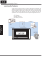
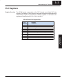
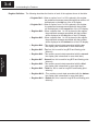
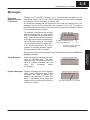
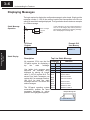
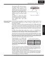
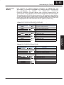
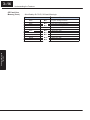
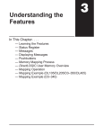
Understanding the
Features
In This Chapter. . . .
— Learning the Features
— PLC Registers
— Messages
— Displaying Messages
— Memory Mapping Process
— DirectLOGIC User Memory Overview
13
3–2
Understanding the Features
Learning the Features
In this section, the subject of how to use the OP–440 features is described. The
details for using messages are covered. We recommend that you study this chapter
before attempting to configure and use the OP-panel. As you proceed through this
chapter, relate the topics discussed with how your operator panel may be
implemented. The concepts discussed in this chapter are applicable to all PLCs.
SPLC Registers
SMessage Operations
SUser Memory Overview
OP–WINEDIT
Understanding the
Features
PLC
Process Data.....
Memory Requirements...
MACHINE
3–3
Understanding the Features
PLC Registers
Register Overview
The OP400 panels communicate to the PLC through user defined PLC data
registers. The starting or “Base” register is assigned during panel configuration and
automatically occupies 12 consecutive 16-bit data registers. In this manual the
registers are identified as M+0, M+1, M+2, thru M+11.
OP–440 Panel PLC Register Map
Top line message selection
Second line message selection
Third line message selection
Bottom line message selection
Top line data
Top line data 2 (for long BCD and floating point numbers)
Second line data
Second line data 2 (for long BCD and floating point numbers)
Third line data
Third line data 2 (for long BCD and floating point numbers)
Bottom line data
Bottom line data 2 (for long BCD and floating point numbers)
Understanding
the Features
M+0
M+1
M+2
M+3
M+4
M+5
M+6
M+7
M+8
M+9
M+10
M+11
Register
Function
Entering Programs
PLC
Register
3–4
Understanding the Features
Register Definition The following describes the function of each of the registers shown in the table.
S Register M+0 – When a number from 1 to 160 is placed in this register,
the predefined message associated with that number will
be displayed on the top line of the LCD display.
S Register M+1 – When a number from 1 to 160 is placed in this register,
the predefined message associated with that number
will be displayed on the second line of the LCD display.
S Register M+2 – When a number from 1 to 160 is placed in this register,
the predefined message associated with that number
will be displayed on the third line of the LCD display.
S Register M+3 – When a number from 1 to 160 is placed in this register,
the predefined message associated with that number
will be displayed on the bottom line of the LCD display.
S Register M+4 – This contains numeric data associated with the top
line display (this is described in more detail later).
S Register M+5 – Top line, this is used for long BCD and floating point
data only.
S Register M+6 – This contains numeric data associated with the second
Understanding the
Features
line display (this is described in more detail later).
S Register M+7 – Second line, this is used for long BCD and floating point
data only.
S Register M+8 – This contains numeric data associated with the third
line display (this is described in more detail later).
S Register M+9 – Third line, this is used for long BCD and floating point
data only.
S Register M+10 – This contains numeric data associated with the bottom
line display (this is described in more detail later).
S Register M+11 – Bottom line, this is used for long BCD and floating point
data only.
3–5
Understanding the Features
Messages
Displaying
Messages on the
LCD Screen
Through the OP–WINEDIT software, up to 160 predefined messages can be
entered and stored in the OP–440. These messages can be 20 characters long and
can include a field for the display of numeric data.
Any predefined message can be displayed on any of the four message lines. The
messages entered during configuration are numbered 1 thru 160. To display a
particular predefined message on the display, simply place that message’s number
in the message selection register.
Example Message:
Mary had a little
white fleeced lamb
To display message #16 here,
place 16 in register M+0.
To display message #22 here,
place 22 in register M+1.
Static Messages
Static messages are text displays which
have no embedded data. The static
messages may be displayed when an
event or condition becomes true. You
enter
the
messages
during
configuration.
Dynamic Messages Dynamic messages are text messages
which include embedded data. These
messages are used to present the
operator with important PLC data. This
data is information which helps the
operator closely monitor and control the
machine or process.
Example Static Message:
SYSTEM RUNNING
Example Dynamic Message:
Zone1 Temp. = ^^^^
Data Value update from PLC register
Understanding
the Features
There are two types of messages which may be displayed on this panel, Static and
Dynamic messages.
Entering Programs
For example, let’s assume that we have
defined message #16 as “Mary had a
little” and message #22 as “white fleeced
lamb”. If we wanted to put these two lines
on the top and second lines respectively,
we would simply need to put the number
16 in register M+0 and 22 in register M+1.
If any number other than 1 thru 160 is
placed in a message selection register,
the associated line will not change.
3–6
Understanding the Features
Displaying Messages
The logic required to display the configured message is quite simple. Simply put the
message number (1–160) in the memory location that corresponds to the line on
which you want the message displayed. The figure below demonstrates an example
of a Static message.
Static Message
Operation
X3
ON
LD
K3
Selects message#
for Top line
OUT
V2000
M+0
In this example, if the PLC’s input signal X3 is
ON, the 16 bit integer (K3) value is placed in
Word register V2000 (M+0), selecting message
#3 to be displayed on the top line.
OP-Panel
Register
Understanding the
Features
M+0
Example PLC
User Memory
V2000 = 3
Message # request
Static Display
ËËËËË
ËËËËË
ËËËËË
Top Line Static Message
Function
All supported CPUs use the first Register
Value
Description
OP-panel register for displaying a M+0
top
line
static
message. M+1
Your ladder logic program must
sequence the message being
displayed by placing an integer
value (1–160) in register M+0. For
second line static messages use
register M+1 for message selection.
Use M+2 for third line static
messages and M+3 for bottom line
static messages.
The OP-panel operating system
automatically updates the latest
messages according to values
placed in the highlighted registers.
M+2
M+3
M+4
M+5
M+6
M+7
M+8
M+9
M+10
M+11
3
Top line message selection
Second line message selection
Third line message selection
Bottom line message selection
Top line data
Top line data 2
Second line data
Second line data 2
Third line data
Third line data 2
Bottom line data
Bottom line data 2
Example Message #3
System Running
3–7
Understanding the Features
Dynamic Message
Operation
Example Message #36:
# widgets sold: 465
Place 36 in register M+3;
message is “# widgets sold: ^^^^”.
To display this, 465 must
be in register M+10.
Examples of dynamic messages. Notice the caret (^) symbols,
which is where data will be when the message is displayed.
Understanding
the Features
For example, let’s say message #36 is “#
widgets sold: ^^^”. Let’s also say that 465
widgets have been sold today. To display
the current number of widgets sold on the
bottom line of the display, you would
place 36 in register M+3 and 465 in
register M+10. The bottom line would
then display: “# widgets sold: 465”.
Entering Programs
You may program message numbers 1–160 to be used as dynamic messages. One
numeric field per line is allowed. Dynamic messages may be displayed on any of the
display lines. The maximum number of digits which may be displayed is five if binary
data format is used or eight if BCD is used when using a single 16–bit register. The
largest number that can be displayed is 99,999,999 when using 32–bit format, and
this must be done using BCD. The figure below shows an OP–WINEDIT screen for
programming dynamic messages.
Enter the message text and place the caret (^) symbol(s) depending on the number
of digits you would like to display. The value range which may be displayed is
0–65,535 integer or 0–99999999 BCD. Choose binary, BCD, or BCD double format
and fixed point decimal placement. When choosing the data format for DirectLogic
PLCs use BCD format, and with Allen-Bradley PLCs use binary.
For dynamic messages which require fixed decimal point placement within the
value, you must use the OP–WINEDIT to perform parameter placement type. For
fixed position decimal points you must enter the decimal directly into the message
text, such as Zone1 Temp = ^^.^^.
3–8
Understanding the Features
Dynamic Message
Top Line
In this example, if the PLC’s input signal X4 is
ON, the 16 bit integer (K5) value is placed in
Word register V2000 (M+0) selecting message
#5 to be displayed on the top line. The data value
in register V3000 (let’s say 1100) is moved into
V2004 (M+4), which is embedded in the top line
message. The top line data value will update as
long as X4 is enabled (ON).
X4
ON
LD
K5
Selects message#
for Top line
OUT
V2000
M+0
LD
V3000
Loads variable data
OUT
V2004
M+4
OP-Panel
Register
Example PLC
User Memory
M+0
M+4
V2000 =5
Message # requested
Top line message data
V2005 =1100
ËËËËË
ËËËËË
Understanding the
Features
Remember, your ladder logic Top Line Dynamic Message
program must select the message
Function
being displayed by placing an Register
Value
integer value between 1 and 160 M+0
Top line message selection
5
(message #) in register M+0. The M+1
Second line message selection
embedded data for the top line
Third line message selection
message is controlled by loading a M+2
Bottom line message selection
M+3
16 bit value into register M+4.
Example Message #5
Zone1 Temp. Sp=1100
The highlighted registers
M+0 and M+4 in this figure
result in displaying this
top-line dynamic message.
Dynamic Message
Third Line
M+4 1100
M+5
M+6
M+7
M+8
M+9
M+10
M+11
X5
ON
LD
K7
Selects message#
for third line
OUT
V2002
M+2
LD
V3001
Loads variable data
OUT
V2010
M+8
OP-Panel
Register
M+2
M+8
Top line data
Top line data 2
Second line data
Second line data 2
Third line data
Third line data 2
Bottom line data
Bottom line data 2
In this example, if the PLC’s X5 input signal is
ON, the 16 bit integer (K7) value is placed in
Word register V2002 (M+2) requesting message
#7 to be displayed on the third line. The data value in register V3001 (let’s say 1101) is moved
into V2010 (M+8), which is embedded in the third
line message. The third line data value will update as long as X5 is enabled (ON).
Example PLC
User Memory
Message # requested
Third line message data
V2002 =7
V2010 =1101
3–9
Understanding the Features
ËËËËË
ËËËËË
Third Line Dynamic Message
Register
Function
Remember, your ladder logic
program must select the third line
message being displayed by placing
an integer value between 1 and 160
(message #) in register M+2.
Example Message #7
The highlighted registers shown in
this figure results in displaying this
third-line dynamic message.
Displaying Data
With a Decimal
Point
Top line message selection
Second line message selection
Third line message selection
Bottom line message selection
Top line data
Top line data 2
Second line data
Second line data 2
Third line data
Third line data 2
Bottom line data
Bottom line data 2
Fixed point numbers are handled by
simply placing a decimal point or period
in
the
message
field
during
configuration. For example, let’s say you
want
to
display
the
message
“Temperature: 73.5” on the top line, and
the message is #47. Enter message #47
as
“Temperature:^^^.^”
during
configuration.
Example Message #47:
Temperature: 73.5
Place 47 in register M+0;
message is “Temperature: ^^^.^”
To display this, 735 must
be in register M+4.
Understanding
the Features
The OP–440 panel allows you to display fixed point numbers, which are numeric
values that have a known decimal point placement and are simply handled as
integer values within the PLC program. The only time you see an actual decimal
point is on the LCD display. An example of a fixed point number is a program that
uses temperature as a control variable, and within the program all temperatures are
scaled in tenths of a degree. The values are integer, so a temperature of 73.5
degrees would be 735 in a data register. For the convenience of the operator, you
would want the LCD display to include the decimal.
Entering Programs
Zone2 Temp. SP=1101
Value
M+0
M+1
M+2
7
M+3
M+4
M+5
M+6
M+7
M+8 1101
M+9
M+10
M+11
3–10
Understanding the Features
Displaying BCD
and Binary
Numbers
Normally, numeric values to be displayed are values contained in one 16-bit
register. One 16-bit register will handle values between 0 and 65535 in binary form,
or between 0 and 9999 in BCD form. For these type numbers, register M+4 is used
for the numeric value for the top line, M+6 for the second line, M+8 for the third line,
and M+10 is used for the bottom line.
ËËËËË
ËËËËË
BCD and Binary Numbers Display
Register
Function
Value
Understanding the
Features
M+0
M+1
M+2
M+3
M+4
M+5
M+6
M+7
M+8
M+9
M+10
M+11
Top line message selection
Second line message selection
Third line message selection
Bottom line message selection
Top line data
Top line data 2
Second line data
Second line data 2
Third line data
Third line data 2
Bottom line data
Bottom line data 2
Displaying BCD The OP–440 will handle large numeric numbers. If you select the option BCD
Double Numbers Double when the display message is being defined, your display can handle
numbers between 0 and 99,999,999. The panel will use data in the register pair M+4
and M+5 for the top line, M+6 and M+7 for the second line, M+8 and M+9 for the third
line, and use M+10 and M+11 for the bottom line. The data must be in BCD.
ËËËËË
ËËËËË
BCD Double Numbers Display
Register
Function
Value
M+0
M+1
M+2
M+3
M+4
M+5
M+6
M+7
M+8
M+9
M+10
M+11
Top line message selection
Second line message selection
Third line message selection
Bottom line message selection
Top line data
Top line data 2
Second line data
Second line data 2
Third line data
Third line data 2
Bottom line data
Bottom line data 2
3–11
Understanding the Features
Example: BCD Double
92345678
9234 must be in register M+5
5678 must be in register M+4.
The configuration of a floating point
number message is similar to any other
message. First, you select the message
number, then you type in the text using
nine caret symbols (^) as a place holder
for each of the nine floating point number
symbols. Next, select the Float option for
the data format.
Example: Floating Point Numbers
PLC Registers
OP–440 Display
12301.789
+123E+04
123.96783
+123E+02
Let’s say you wanted to configure message #58 to display a floating point number.
In the OP–WINEDIT software, select OP–440 as the module type, and then select
message #58 with the mouse. Type in the following message: “Float Pt ^^^^^^^^^”
and select floating point as the message format.
To display a number , simply move it into the desired display line data registers and
load the appropriate message number into the corresponding line message
selection register. For example, if you display the number 632.15 in message #58,
it will be displayed as “Float Pt # +632E+02”.
Understanding
the Features
Displaying Floating The OP–440 has the capability to display Floating Point (or Real) numbers if you
select the option Float when the display message is being defined in the
Point Numbers
OP–WINEDIT software.
Floating point numbers can only be used with the D2–250, D3–350, and D4–450
CPUs since they are the only compatible CPUs that support the IEEE 32-bit floating
point number format, which is where the floating point numbers are stored. They
always occupy two 16-bit register locations regardless of the size of the number. See
the PLC User Manual for more information on the IEEE 32-bit floating point number
format.
An IEEE 32-bit floating point number has a range of –3.402823E+38 to
+3.402823E+38. The OP–440 will be able to display any number within that range.
The panel always uses the format X.XXEXX to display the numbers.
The panel does not have the ability to display all the significant digits of a floating
point number, it only displays the first three significant digits. The OP–440 truncates
the remaining digits so you always see the true number. The two examples below
show the data contained in the PLC registers and the corresponding value displayed
on the panel in its format. Notice how the data is truncated.
Entering Programs
When placing a BCD double number in
the display registers, the first register
numerically in the sequence of two
registers (M+4, M+6, M+8 or M+10) will
contain the four least significant digits of
the number. The second register in the
sequence (M+5, M+7, M+9 or M+11)
contains the data for the four most
significant digits of the BCD double
number.
For example, to display the number
92345678 on the top line of the display,
the top line data registers, M+4 and M+5,
must
contain
5678
and
9234
respectively.
3–12
Understanding the Features
Memory Mapping Process
OP Base
Register Memory
Definition
Each OP–440 is assigned 192 bits of PLC user memory which will be used as the
OP-panel database. The ladder logic program must access this assigned OP-panel
memory. Let’s take a closer look at this user memory and how it relates to the
OP-panel features.
As discussed earlier, regardless of which PLC product you are using the base
registers address M+0 through M+11 are formatted the same. In this manual, when
the terms M+0 through M+11 are used, this identifies which base register(s) are
affected for the topic being covered.
Understanding the
Features
Base Address
Manual Reference
M+0
M+1
M+2
M+3
M+4
M+5
M+6
M+7
M+8
M+9
M+10
M+11
Operator Panel
Base Memory
=
=
=
=
=
=
=
=
=
=
=
=
Function Description
Top line message selection
Second line message selection
Third line message selection
Bottom line message selection
Top line data
Top line data 2
Second line data
Second line data 2
Third line data
Third line data 2
Bottom line data
Bottom line data 2
PLC user memory is assigned to each panel with the OP–WINEDIT configuration
software. For new OP-panels and add-on applications, the programmer must define
twelve 16 bit registers for PLC interface. Below is a figure showing memory layout for
DL05, DL105, DL205, D3–350, and DL405 PLC’s and uses V2000–V2013 for the
OP–440 panel. See the next page for other PLC product memory usage examples.
You must reserve 192 bits (twelve 16-bit
registers or twenty-four 8-bit registers)
which are used to process data between
the panel and your PLC. You must
configure the Base register for the
OP-panel. This base register address is
stored in the OP-panel program.
CPU User’s memory
V2000
V2001
V2002
V2003
V2004
V2005
V2006
V2007
V2010
V2011
V2012
V2013
OP–440 Panel
Data Base
16 bits
M+0
M+1
16 bits
M+2
16 bits
M+3
16 bits
M+4
Panel
No.1
16 bits
M+5
16 bits
M+6
16 bits
M+7
16 bits
M+10
16 bits
M+11 . 16 bits
Total:Panel
192
bits
M+12
No.1
16 bits
M+13
16 bits
Total: 192 bits
3–13
Understanding the Features
OP-Panel User
Memory
Let’s examine the different address conventions for DirectLOGIC and
Allen-Bradley. For example, the DirectLOGIC address references are octal, and
DirectLOGIC
DL05/DL105/
the
Allen-Bradley
is
decimal.
The
DL205/D3–350/DL405 OP-panel address uses V-memory registers which are
16-bit registers. The DL305 family uses reference assignments with 8-bit registers.
This means that the DL305 will require twenty-four 8 bit registers for data handling.
The Allen-Bradley memory is defined with a reference (Nx) which represents the
memory area and (:n) which defines the word within the memory area. Please refer
to the appropriate CPU User manual for the PLC product you are using.
DirectLOGIC DL05/DL105/DL205/D3–350/DL405
M+0
M+1
M+2
M+3
M+4
M+5
M+6
M+7
M+8
M+9
M+10
M+11
Top line message selection
Second line message selection
Third line message selection
Bottom line message selection
Top line data
Top line data 2
Second line data
Second line data 2
Third line data
Third line data 2
Bottom line data
Bottom line data 2
DirectLOGIC DL305 (DL330 and DL340)
Example Address
R400/R401
R402/R403
R404/R405
R406/R407
R410/R411
R412/R413
R414/R415
R416/R417
R420/R421
R422/R423
R424/R425
R426/R427
Function
M+0
M+1
M+2
M+3
M+4
M+5
M+6
M+7
M+8
M+9
M+10
M+11
Top line message selection
Second line message selection
Third line message selection
Bottom line message selection
Top line data
Top line data 2
Second line data
Second line data 2
Third line data
Third line data 2
Bottom line data
Bottom line data 2
Understanding
the Features
V2000
V2001
V2002
V2003
V2004
V2005
V2006
V2007
V2010
V2011
V2012
V2013
Function
Entering Programs
Example Address
3–14
Understanding the Features
OP Panel User
Memory (Cont.)
Allen-Bradley SLC 5/03, 5/04 and Micrologix
Example Address
Understanding the
Features
N7:0
N7:1
N7:2
N7:3
N7:4
N7:5
N7:6
N7:7
N7:8
N7:9
N7:10
N7:11
Function
M+0
M+1
M+2
M+3
M+4
M+5
M+6
M+7
M+8
M+9
M+10
M+11
Top line message selection
Second line message selection
Third line message selection
Bottom line message selection
Top line data
Top line data 2
Second line data
Second line data 2
Third line data
Third line data 2
Bottom line data
Bottom line data 2
3–15
Understanding the Features
DirectLOGIC User Memory Overview
D0–05
V-Memory
D1–130/D2–230
V-Memory
D2–240
V-Memory
D2–250
D3–350
D4–440
V-Memory
D4–430
V-Memory
D4–450
V-Memory
V1200
V1400
V2000
V2377
V1400
V7377
V7377
V10000
V10000
V2000
ÉÉÉÉ ÉÉÉÉ ÉÉÉÉ
V40600
V40637
V40600
V40617
V40600
V40617
D3–340
R-Memory
ÉÉÉÉ ÉÉÉÉ
ÉÉÉÉ
ÉÉÉÉ
R016
R037
R100
R106
R400
R400
R563
R563
R700
R767
Understanding
the Features
D3–330
R-Memory
V7377
ÉÉÉÉ
ÉÉÉÉ
V40600
V40635
V17777
ÉÉÉÉ
ÉÉÉÉ
V40600
V40677
V37777
ÉÉÉÉ
V40600
V40777
ÉÉÉ
ÉÉÉ
ÉÉÉ
User Data Space available for OP-panels
Internal Relay Memory
DirectLOGIC PLCs use octal addressing, as indicated by the shaded areas.
Entering Programs
V3777
V7377
R016
R037
V1400