1
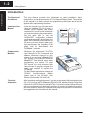
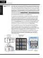
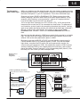
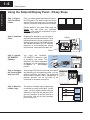
1
Getting Started
1
In This Chapter. . . .
— Introduction
— Using the Setpoint/Display Panel ... 5 Easy Steps
1–2
Getting Started
Getting Started
Introduction
The Purpose of
this Manual
This User Manual provides user information on panel installation, panel
configuration, and programming the OP1312 Setpoint/Display Panel. The purpose
of this manual is to teach concept and programming techniques which may be
applied while implementing the panel.
Contents of the
Manual
Inside this manual you will learn about
using the OptiMate OP–1312 panel. It
includes wiring diagrams and power
requirements, as well as the information
you need for selecting the proper cables.
We will show how to use the
OPWIN–EDIT configuration software
(purchased separately) to configure your
panel. And in the back of this manual, we
will show you some simple ladder logic
that demonstrates the versatility of the
panel, both for Allen-Bradley and
PLCDirectt products.
How to
Use the
OP-1312
OP-1312
The OPĆ1500 and OPĆ1510
Operator panels may be
reconfigured to exchange data
with
your
programmable
controller.
Supplemental
Manuals
Reference the appropriate PLC/CPU
User Manuals for the commands and
address references required for your
system. If you are using a DirectLOGIC
PLC product, you will want to keep the
DirectSOFT User Manual handy while
programming your system. For other
PLC brands you must reference their
User manuals to properly program the
ladder logic required to operate the
OP-panels.
For Multi-Panel applications utilizing the
OPĆ9001
Communications
Master
please refer to the OP–9001 User
Manual (Part Number OP–9001–M).
Technical
Assistance
After completely reading this manual, if you are not successful with implementing the
OP–1312, you may call PLCDirect at (800) 633-0405, Monday through Friday from
9:00 A.M. to 6:00 P.M. Eastern Standard Time. Our technical support group will work
with you in answering your application questions. If you have a comment or question
about our products, services, or manuals which we provide, please fill out and return
the suggestions card included with this manual.
Getting Started
Chapters
1–3
This table provides an overall description of the topics covered within this manual.
Getting Started
2
Installation and
Specifications
3
Configuring Your Panel
4
Applying Ladder Logic
Shows how to prepare for system installation, including specifications and
mounting instructions. Includes connecting cables part numbers and
specifications.
shows how to configure the panel. The OP–WINEDIT for windows
contains Help windows which will assist with configuring the panel.
Explain the memory map and how to program and operate the panel.
Getting Started
1
Introduces the physical and functional characteristics. Also provides
introduction to planning your system.
Getting Started
1–4
Getting Started
How the OP-1312
Works
You’ll notice the OP-1312 has three LED windows with four labels beneath each of
them. There are a total of twelve labels. Each of the labels refer to user-defined field
points. These field points are actually memory locations inside your PLC where data
is stored. During configuration with the OPEditor software, you define and link these
field points to your panel. You can make a field point a read only location–in which
case, we refer to it as display data. Or you can designate a field point to store
setpoint data–in which case, the field point is a read/write location. The three LED
windows allow you to either read the display data or read and write the setpoint data.
Each label has an LED beside it. When an LED is lit, it means you have connected
the corresponding field point (in the PLC) to the panel window immediately above
the corresponding label. Let’s look at an illustrated example.
The illustration at the bottom–right of the page, shows a display window with its
four labels. Notice that beneath each bank of four labels are arrow keys and a
<SELECT>key. Pressing any<SELECT> key successively moves you up and
down the labels immediately above the key; and as their corresponding LED
becomes lit, the window displays the data from the field point memory location
that is linked to the label. If you move to a label whose field point has been setup
by you to hold setpoint data, then you can use the UP or DOWN ARROWS to
change the value shown in the window. The UP or DOWN ARROWS have no
effect,however on field points that have been setup for display data.
Now look at the memory map in the illustration. We have used the OPEditor
during configuration to map each of the 12 field points and a forcing function to
consecutive memory areas inside the respective PLC. For the PLCDirect
product, it started at V2000. For the Allen-Bradley product it started at N7:0. The
memory map shown is merely an example. Your base address in the PLC for the
mapping can start at any available memory location, as long as you use
consecutive locations. The download precedure (explained later) will consume
224 consecutive bits of memory–devoted entirely to the OP-1312 operations.
Below we show this as 14 consecutive 16-bit registers. If you are using the
DL305 family, it would consume 28 consecutive 8-bit registers. We’ll give you
specific examples later.
CPU Memory
OP–1312 to CPU
Memory Map
PLCDirect
Display Locations
Allen-Bradley PLCDirect
–OR–
Allen-Bradley
N7:0
V2000
Location 1 data
N7:1
V2001
Location 2 data
N7:2
V2002
Location 3 data
N7:3
N7:4
V2003
V2004
Location 4 data
Location 5 data
Target Production
N7:5
V2005
Location 6 data
Current Production
N7:6
V2006
Location 7 data
N7:7
V2007
Location 8 data
N7:8
V2010
Location 9 data
N7:9
V2011
Location 10 data
N7:10
V2012
Location 11 data
N7:11
V2013
Location 12 data
N7:12
V2014
Force data info
N7:13
V2015
Data to be forced
Press Temperature
Air Pressure
Press to select location
to change or view
Press arrow
keys to change
setpoints
1–5
Getting Started
Numbers refer to
field point
designations
While we explained on the opposite page how the memory mapping process
between the panel and the PLC takes place, we haven’t yet explained how you use
the linked “field points” in your PLC operations. This is done with ladder logic.
Suppose you have a DL205 or DL405 family PLC. Below (center) shows the
memory mapping if we have used V2000 as our base register address. In this
example, we are tracking “current production” against our “target production”.
Look at the ladder logic on the left in the diagram.
X10 is an input from a photoeye to a PLC counter (CT0). X10 is the input that
increments the counter and X11 is connected to a reset button. For purposes of
our illustration, we don’t need to know anything else about the process. Looking
again at our labels and display window, be aware that the labels are numbered 1
through 12 left-to-right, top-to-bottom. So Location 1 refers to the Target
Production label. Location 2 refers to the Current Production label, and so
forth.
We are using the data placed in V2000 as our preset for the counter in our ladder
logic. You will notice at the upper right-hand side of the illustration that we have
entered 1243 as the data (setpoint) we place in V2000.
Because we are using a DL205 or DL405, we know that the current count for
Counter Number Zero (CT0) is always stored in V1000. Thus with the ladder
logic shown, everytime the X10 comes ON and increments the counter, the
current count gets copied into V2001. We wanted this copied to V2001 because
we have configured V2001 to be a display data point (read only), and we have
placed the words “Current Production” on its corresponding label (Label 2). See
how easy it is? We’ll show you other examples later.
Ladder Logic Example ( PLCDirect )
Target production is written to V2000 by the
OP-1312.
X10
X11
CNT
CT0
V2000
Current production count gets copied
into V2001, which is being read by
the setpoint unit. (V1000 holds the
current count for CT0.)
OP–1312 to CPU
Memory Map
Location 1
Setpoint
V2001
Location 2
Display
V2002
Location 3
V2003
V2004
Location 4
V2005
Location 6
V2006
Location 7
V2007
Location 8
V2010
Location 9
LD
V1000
V2011
Location 10
V2012
Location 11
OUT
V2001
V2013
Location 12
V2014
Force data
V2015
Data to force
X10
Display
V2000
Location 5
Target Production
Current Production
Press Temperature
Air Pressure
Target Production
Current Production
Press Temperature
Air Pressure
Use keys to
change setpoint
Press SELECT to move
to the next data location. Here we have
moved to Label 2 and
we are reading the current count out of
V2001.
Getting Started
The Interaction
with Ladder Logic
1–6
Getting Started
Getting Started
Using the Setpoint/Display Panel...5 Easy Steps
Step 1: Prepare
Your Field Point
Labels
First, you need to prepare the labels for each of
the field points. The labels insert into plastic
sleeves behind the main cover. To access the
sleeves, you merely snap loose the front bezel.
Decide ahead of time which field points are
display only and which are read/write
setpoints. You need this information for your
configuration process.
Step 2: Install the
Panel
Preparing for installation, you will want to
check the individual specifications. These
include dimensions, power requirements,
cabling requirements, and NEMA ratings.
We include information you will need for
mounting; i.e. cutout dimensions, cabling
requirements, components needed, etc.
Panel
Step 3: Load the
OP–WINEDIT
Software
You need the OptiMatet
OP–WINEDIT software in order
to configure your panel. This
software is the same regardless
of whether you are connecting to
PLCDirect or Allen-Bradley
product.
Step 4: Configure
the Panel to Work
with your CPU
After setting a DIP switch on the rear of the panel
and attaching the programming cable, you are
ready to configure your panel. The simple and
easy-to-follow screens make configuration a
painless process. You do not have to be
connected to the panel at this point.
Step 5: Write the
Ladder Logic
The amount of ladder logic programming
knowledge you need is very basic. In most
cases, you are already familiar with the
elements of logic that are required. We’ll
give you examples in the final section of
this manual, and you will see right away
just how easy it is.
Cables
External Power
Your PC
OptiMate
OptiMate Configuration
Editor Version 3.2 6/98
DIP
Switch
X10
X11
X10
CNT
CT0
V2000
LD
V1000
OUT
V2001