1
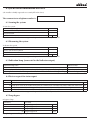
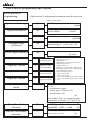
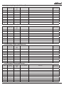
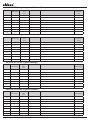
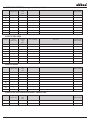
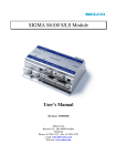
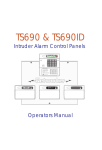
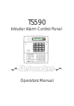
GSM AXEMAX
Installation and user’s manual
VERSION 5.0
1
2
Contents
1 INTRODUCTION
4
1.1Important notices
4
2. Features
4
3 Device installation
5
3.1 Checking the supply contents
5
3.2 Finding a location
5
3.3 Providing a power supply
5
3.4 Inserting the SIM card
5
3.5 Feeder connections and locations of system elements
6
Description and use of system elements
6
Description of terminals
6
3.6 Example input wiring diagrams for different applications and input mode descriptions 7
4 Description of functions and customized parameters
9
4.1 User code change (Y 1)
9
4.2 Test call – test message transmission
9
( Y 2, Y 3, Y 4, Y 76 (system parameter - careful))
9
4.3 Control SMS message for device status (Y 5)
9
4.4 System real time clock setting (Y 6)
9
4.5 Control SMS message for pre-paid SIM card credit (Y 8)
9
4.6 Output control setting and output status description (Y 11 - Y 18)
9
4.7 Control SMS message to set off alarm (Y 29)
10
4.8 Control SMS message to arm/disarm ( Y 32, Y 33)
10
4.9 Control SMS message to switch on/off listening in ( Y 37, Y 38)
10
4.10 Control SMS to bypass and unbypass loops ( Y 45, Y 46)
10
4.11 Parameter settings to control lighting by ring-through ( Y 47, Y 48, Y 49)
10
4.12 Telephone number definition for control by ring-through (Y 101 až Y 164)
10
5 Programming transmissions of system generated information
10
5.1 transmission item definition
10
6 Description of system functions and parameters
11
6.1 System code change ( Y 61)
11
6.2 Operative number (Y 62)
11
6.4 Unbypass of bypassed loops on disarm (Y 64)
11
6.5 Credit request number (Y 69)
11
6.6 Input 1 – 4 mode definition (Y 70 - Y 73)
11
6.7 Arm/diarm control mode (Y 74)
11
6.8 Test call method selection (Y 76)
11
6.9 SMS to ARC format selection (Y 77)
11
6.10 Outgoing delay (Y 78)
11
6.11 Incoming delay (Y 79)
12
6.12 Alarm output activity duration (Y 80)
12
6.13 Relay 1 and Relay 2 function definition ( Y 82, Y 83)
12
6.14 Pulse duration on Relay 2 by ring-through (Y 86)
12
6.15 Close Relay 1 in complementary function mode to Relay 2 (Y 87)
12
6.16 Alarm number restriction ( Y 93)
12
6.17 BELL transistor output (Y 94)
12
7 Description of the system LED and JUMPER for factory settings
12
7.1 LED
12
7.2 JUMPER for factory settings
12
8 System control information overview
13
8.1 Arming the system
13
8.2 Disarming the system
13
8.3 Indication lamp (connected to the Indicator output I)
13
8.4 Device request for status report
13
8.5 Loop bypass
13
8.6 Loop unbypass
14
8.7 Remote control
14
8.8 Listening-in microphone control
14
8.9 Lighting up garden lighting and opening garage door
14
9 Example wiring diagrams
14
9.1 Device application as the garage door primary control unit
14
10 GSM AXEMAX programming logic diagra
16
GSM AXEMAX programming logic diagram
18
11. Specifications
24
3
1 INTRODUCTION
The GSM AXEMAX security system is a multi-purpose, fully programmable system intended for the protection of private
houses, apartments, weekend houses which can also be successfully employed to secure moderately-sized office, warehouse
and production buildings. The principal advantage of the product is the integration of a fully-fledged security system with a
GSM communicator enabling the system to communicate all the necessary information (alarms, resets, faults, armed/disarmed status, etc). The system is also capable of using outputs from the device to remotely control domestic appliances (lighting, heating, pumps, watering, garage door, etc.). When operated by itself, the system can be used as a powerful device with
four inputs and two outputs. Information generated by the system can be sent via SMS text messages or voice messages to
pre-defined telephone numbers using GSM mobile networks.
The design of the device provides maximum safety of operation while the in-built monitoring of all operational states ensures a high reliability of the transmission of the desired information (in particular alarms).
The advantages of the GSM AXEMAX communication system and GSM technology are:
• mobility – the message is delivered regardless of the immediate position of the user – message receiver
• operability – the user can immediately respond to the message received – take action to stop the culprit, control the equipment or installation
• independence of the fixed line network (can be installed regardless of wired telephone connections).
• low operating costs – the system design ensures maximum utility at minimum operating cost. The operating costs depend
on the number and type of message sent.
The important device parameters are programmable. The parameter settings allow the user to customize the system to best
respond to his needs. The settings are stored in an EEPROM memory – cannot be erased by power supply failures.
1.1 Important notices
- The GSM AXEMAX communication module is supplied excluding the SIM card (activation). It is therefore necessary that
the SIM card of the operator of your choice is inserted into the device before the module is started. Instructions concerning
SIM card installation are below under 3.4.
- If the device is to be used to control garage doors, gates, etc., it absolutely necessary that the door is fitted with an
infrared detection zone or stop bars so that it cannot be lowered when there is an object present in the doorway. The door
can only be remotely controlled when it is visible and when there is clearly no object in the doorway.
- If you plan to use the device as a primary control unit for the garage door you must observe the rules concerning the wiring described under 9.0.
2. Features
-
built around the SIEMENS MC39I industrial module
4 balanced inputs with multiple functional modes
2 relay outputs – controlled by an SMS text message, or by a call from a pre-programmed number
optional relay output status change by a local push-button
2 transistor outputs -sounder, preliminary alarm, status indication
power supply 12-35V dc or 9-24V ac
integrated emergency power supply battery charging and its dynamic testing
simple security system mode with optional control by calling from a pre-programmed number
information transmission by SMS messages and voice calls up to 8 telephone numbers
transmission of SMS messages related to the device operation (power supply outage and restore, AKU fault)
fault messages – power supply outage and restore, emergency power supply battery fault
operation check calls, remote inquiry on the device status
listening-in to the monitored area
with an extension module for video capture transmission
remote and local programming by PC
remote programming by SMS
4
3 Device installation
3.1 Checking the supply contents
The standard GSM AXEMAX system supply contains the following:
- GSM AXEMAX device
- external antenna with GSC connector
- set of balancing resistors (4x10K, 4x2K)
- installation and user’s manual
3.2 Finding a location
- The system must be situated away from heat sources to prevent excessive heat gain.
- The module should be protected against direct sunlight to prevent its heating
- When installing the device in a damp environment (garage door control) be sure to install waterproof cable bushings and if
necessary use a suitable sealing compound.
- Fix the device in the housing by means of the enclosed distance pieces using either stick-on squares or drill holes in the
bottom of the housing. Mark the hole positions using the template appended at the end of the manual.
- The magnetic antenna should be placed at a sheet metal part, such as the control panel (CIE) case, etc.
3.3 Providing a power supply
The device can be powered both by direct and alternating current, for voltage levels see the specifications
The power supply must be designed for the current levels given in the specifications.
If the device is to be used as a security system or in applications requiring an emergency power supply battery the voltage must not be lower than 16V dc or 14V ac. If the application does not require an emergency battery (either not necessary
or the power supply source is already backed up), it need not be installed.
The sensors are supplied with power from the AUX 12V output designed for loads up to 300mA, if the conditions
above are to be met the output will be backed up.
The system monitors the main power supply level. Whenever it drops below 11.5V dc or is lost completely (when the
emergency AKU is being used) a pre-defined SMS message is automatically sent informing of the power outage. In a similar
way, a message is sent when the power supply is restored.. This applies to situations when the power outage or drop exceeds 10
minutes, the time interval is defined to eliminate oscillation around the monitored value of 11.5V.
The emergency battery is dynamically tested after every 24 hours. If the system detects an AKU fault, an SMS message
can be sent, when required.
3.4 Inserting the SIM card
- Before inserting the SIM card in the module, it must be set as follows
1) insert the SIM card intended for the device into another telephone outside the device
2) disable the prompt to enter the PIN code (consult your mobile phone manual), if the operator does not allow switching off
the PIN code (applies to some operators abroad) set the PIN code to 1234.
3) delete all the SMS messages on the SIM card, i.e. incoming, sent, to be sent … (to prevent any possible problems when starting the device)
4) check the SMS centre number setting – obtained by the operator
5) remove the SIM card from the telephone and insert it into the device (before removing the SIM card switch off the telephone in the standard manner, not by removing the battery!)
5
3.5 Feeder connections and locations of system elements
Antenna connector
situated at the GSM module
at the bottom of the device
Jumper for reset to factory settings
Image digitizer connector
Ac power supply
Dc power supply
Back-up battery connection
Listening-in microphone
connector
Description and use of system elements
- Antenna connector – to connect the antenna (part of the supply)
NOTE : when handling the GSC connector of the antenna cable never hold the cable, use an appropriate tool to grab the
connector body.
- PC connector – to link to a PC for configuration and system history downloads. Use a suitable linking cable such as the 1:1
extension cable (canon 9F/M) for the canon 9PIN serial cable (with 2,3,4,5 terminals wired).
- Jumper for reset to factory settings
Factory settings reset procedure: Switch off power and disconnect AKU, insert JUMPER, switch on the device, the LED is on,
once the factory settings reset is complete – the LED flashes switch off power, remove JUMPER and restore power supply.
Description of terminals
- RE1, RE2 - NO contacts of relay 1,2
NOTE: if you connect relays controlling mains voltage you must use good quality relays (such as FINDER 40.51 or
40.61) and fit the switching contacts with a good quality quenching capacitor for ac mains voltage with a capacity of
10nF. To control larger installations the relay should have a separate power supply - AUX – emergency output of 12V/300mA power supply voltage
- ~ - terminals to connect ac power supply
- +~ - terminal to connect the positive pole of dc power supply
- - terminal to connect the negative pole of dc power supply
- AKU – terminals to connect emergency battery 12V / 1.3 to 7Ah
- IN1 - IN4 – input terminals (example wiring diagrams shown below)
- BELL - transistor output (switching to earth) 200mA for the sounder or preliminary alarm indicator (to be used only against the AUX +12V terminal)
- Indicator – terminal to connect the system status LED indicator (disarmed - off, armed - on and the number of flashes
shows the number of the activated input – walk-through test.) (to be used only against the AUX +12V terminal)
6
3.6 Example input wiring diagrams for different applications and input mode
descriptions
Example wiring diagram for mode 1 – single balanced input
suitable for connecting the alarm CIE, fire-alarm system ...
Each outbalancing or balancing of the input causes a message to
be sent as programmed
outbalancing the input does not cause the alarm contact to close,
Example wiring diagram for mode 2,3,4,5 – double balanced input
this mode is used as a standard double balanced input for connecting sensors to TAMPER contact
- mode 2: alarm loop 24H not activating an alarm output, suitable
for panic buttons
- mode 3: alarm loop 24H activating an alarm output
- mode 4: alarm loop - immediate
- mode 5: alarm loop - delayed
sensor 1
sensor 2
sensor 3
Example wiring diagram for up to 3 sensors connected to a single loop
Example wiring diagram for mode 6 - external RELAY 2 control button of in flip flop mode
7
Example wiring diagram for mode 7 – input function inhibiting output response to a ring-through
the relay contact may stand for an infrared detection zone contact
guarding the garage doorway. Closed contact means doorway
clear.
Example wiring diagram for mode 8 – control pulse input
the contact represents a relay switching contact in the control
keyboards, in the remote control receiver or a hidden button
Example wiring diagram for mode 9 – switching control input
contact closed – system disarmed
contact open – system armed
Example wiring diagram for mode 10,11 – control button of remotely controlled relays
- mode 10: pressing the button causes RELAY 1 to transfer from
its current status
- mode 11: pressing the button causes RELAY 2 to transfer from
its current status
8
Example wiring diagram for mode 12, 13 – monitoring device
status for relay control
This mode is used to synchronize the status of the remotely controlled device and the GSM AXEMAX device for pulse control.
Closed contact of the remotely controlled device signals the device is on and vice versa. Closed contact signifies application on.
- mode 12: establishes RELAY 1 status
- mode 13: establishes RELAY 2 status
NOTE: Mode 12 or 13 can be assigned to a single input only.
This mode makes sense only when an output in the “free pulse control” mode is used to control a device. The status detected by
the input will be displayed in the status message for the given relay so that the displayed information on the device status will
always be valid, however it will not be the relay status but the device status. If you send a switch-on command to a device that is
already switched on no pulse will be generated which is desirable.
4 Description of functions and customized parameters
The device can be programmed by SMS messages (in the same way as GSM AM-MINI and GSM AM-COMPACT)
System parameters require that a user code is used.
Command Y 51 sent to the device with the syntax 4444 Y 51, (where 4444 is the factory user code, the separator – comma- is
required) will cause the device to return the parameter values separated by commas in the following order:
Y 2, Y 3, Y 4, Y 5, Y 8, Y 11, Y 12, Y 15, Y 16, Y 32, Y 33, Y 37, Y 38, Y 45, Y 46, Y 47, Y 48, Y 49
Brief description of customized parameters
An overview in the form of a diagram can be found under 8.0
4.1 Change user code (Y 1)
The user code is used for programming customized parameters
4.2 Test call – test message transmission
( Y 2, Y 3, Y 4, Y 76 (system parameter – careful))
Used to regularly check whether the function works correctly. Based on the parameter settings the device automatically sends
a message to pre-set users. The device can send the user a test call either in the form of an unanswered call (rings 1x or 2x) or
in the form of a direct call when after pick-up the user hears a pre-defined number of tone marks (blips). The device calls 3x, if
you pick up the call the cycle is terminated. The required settings are the test call interval in days (Y 2), parameter
Y 3 specifying in hours when the 1st call is made. Parameter Y 4 specifies the number of tone marks, if the value is set to 1, an
unanswered call will be made, if set to 0 the test call is not initiated at all. If parameter Y 76 is set to 1, there will be no test calls
but an SMS messages with device status information will be sent at pre-set intervals. Those alarm message receivers who are
and who are not to be sent the test message are specified in the transmission item definition, see under 5.x
4.3 Control SMS message for device status (Y 5)
The GSM AXEMAX device allows the user to enquire, at any time, about device status. The term device status incorporates the
status of inputs, outputs, power supply and signal. The device status is sent to the user at the number from which the control
SMS message was sent. The control message simultaneously functions as a password.
4.4 System real time clock setting (Y 6)
The system uses its own real time clock when storing the event history which needs to be set.
4.5 Control SMS message for pre-paid SIM card credit (Y 8)
After sending this command the device will return, at any moment, the amount of its pre-paid SIM card credit. It is necessary
that the parameter Y 69 setting is accurate.
9
4.6 Output control setting and output status description (Y 11 - Y 18)
These parameters specify a command to switch on/off relays and the way their description will be interpreted in the status
message.
4.7 Control SMS message to set off alarm (Y 29)
This parameter defines the command to set off the alarm over a pre-set period (see Y80)
4.8 Control SMS message to arm/disarm (Y 32, Y 33)
Commands to control the system
4.9 Control SMS message to switch on/off listening-in (Y 37, Y 38)
These commands permit or prohibit the system to pick up voice calls. If pick up is enabled, and listening in is switched on, the
device will pick up each voice call and link up the listening-in microphone.
4.10 Control SMS message to bypass and unbypass loops ( Y 45, Y 46)
As any CIE, the GSM AXEMAX system can be set to bypass any of the loops in use (when a sensor is faulty, etc.)
4.11 Parameter settings to control lighting by ring-through (Y 47, Y 48, Y 49)
Using this function is assumed in connection with garage door and gate control whereby the system makes it possible to
switch on garden lighting for a period given by parameter Y 49 simultaneously with opening the gate. To prevent the lighting from going on during daylight the user can set from (Y 47) and until when (Y 48) the lighting is to be switched on. If the
lighting is to go on always the same value parameters Y 47 and Y 48 must be set. The same conditions apply to lighting (tel.
number, etc.) as for opening the gate or system status changes. See below.
4.12 Telephone number definition for control by ring-through (Y 101 to Y 164)
These parameters can only be programmed using PC software. They specify the telephone numbers to which the device responds. A detailed description including time zones is available in the program (GSMAXEMAX.exe)
5 Programming transmissions of system generated information
5.1 transmission item definition
Each information item generated by a change of status (close - balance, open - unbalance) of any of the inputs can be assigned a transmission. These definitions are made using a separate programming block starting, apart from the user code, with
the control character X,
Under the standard definition method the complete programming block of transmission consists of the following items, separated by a comma.
Number of repetitions
- SMS message text to be sent when the given input is interfered with
- write TONx if information is to be sent by a voice message
tel. number, N= do not send a test call to this number
P= sending test messages to ARC according to parameter Y 77
required separator
sequence of the message assigned to the input
required separator
input specification
gap (required entry)
control character
access code
• X – control character
• - gap is a required character
• 1R – defines for which input the transmission is programmed (1R means input 1 outbalance). This item can take the following values: 1R, 1S, 2R, 2S, 3R, 3S, 4R, 4S, TR, TS, UV, UO, AR, DA, BA, RI
10
• 1 – message sequence for the given input, up to 8 messages can be entered for each input (only 2 for input RI)
• tel. number – entering the telephone number to which the SMS or voice call is to be delivered
If preceded by N, it is a command for the device not to forward test calls to that number, without the N character test calls
will be sent. When the P character is entered, test messages will be sent to this number, see parameter Y 77.
• message – specify text to be sent to the given number, maximum length of the text is 46 characters. The text is free without
any restrictions, except the comma character “ , “. If TONx is entered in the text item the transmission will take place as a call
with the voice message x=1 or x=2 (the voice messages are pre-recorded).
• repetition – if the transmission is to take place several times (up to 3x), enter the value 2 or 3. No entry is needed for the
value 1.
6 Description of system functions and parameters
The system code is required to work with system parameters.
Command Y 81 sent to the device with the syntax 4444 Y 81, (where 4444 is the factory system code, the separator – comma
– is a required character) will cause the device to return the parameter values separated by a comma in the following order:
Y 62, Y 63, Y 64, Y 69, Y 70, Y 71, Y 72, Y 73, Y 74, Y 76, Y 77, Y 78, Y 79, Y 80, Y 82, Y 83, Y 86, Y 87,
Y 93, Y 94, Y 99, firmware version, GSM signal intensity valued 0-31
6.1 System code change (Y 61)
The system is used for programming system parameters.
6.2 Operative number (Y 62)
This is an important telephone number with a high probability that the call will be picked up (e.g. the exact time). The device
calls this number when it has failed to establish a connection with any telephone number during a test call. It is used to fulfil
the requirement of the operator to make a call within a prescribed time limit for pre-paid SIM cards.
6.3 Redirect from number (Y 63)
The telephone number from which the operator sends information SMS messages, e.g. on the validity of pre-paid SIM cards.
Messages from this number will be redirected to all of the call receivers programmed at least 1x in alarm transmissions. The
number depends on the GSM operator used.
6.4 Unbypass of bypassed loops on disarm (Y 64)
This parameter specifies whether the bypassed loops will be unbypassed when the system is disarmed.
6.5 Credit request number (Y 69)
The number used to obtain credit for pre-paid SIM cards, depends on the operator.
6.6 Input mode definition 1-4 (Y 70 - Y 73)
Specify depending on the use of the given input, for a detailed description see the programming logic diagram.
Note: for mode 8 to function properly you must correctly set parameter Y 74.
6.7 Arm/disarm control mode (Y 74)
This parameter specifies the optimum variety of system control. Related to pulse control of one of the 4 inputs set to mode 8.
6.8 Test call method selection (Y 76)
As required, specify either a test call or a test SMS message. The test calls or messages will be initiated at an interval set in parameter Y2, Y3, Y4
6.9 SMS to CMS format selection (Y 77)
The system offers a facility for sending regular test messages to CMS. The messages are initiated at an interval specified in test
calls (see above) and can have the following format.
11
1, standard status message
2, string for CMS (max 15 characters) + standard status message
3, string for CMS (max 15 characters)
Note the format of the message is determined by the 1st character which takes on the value 1, 2 or 3.
6.10 Outgoing delay (Y 78)
Defines the outgoing message delay in seconds.
6.11 Incoming delay (Y 79)
Defines the incoming message delay in seconds.
6.12 Alarm output activity duration (Y 80)
Defines the alarm output activity duration in seconds
6.13 Relay 1 and Relay 2 function definition ( Y 82, Y 83)
Defined depending on the intended use of the relay, for a detailed description see logic diagram for programming.
6.14 Pulse duration on Relay 2 by ring-through (Y 86)
Defines the pulse duration on Relay 2 in seconds in the pulse by ring-through mode
6.15 Close Relay 1 in complementary function mode to Relay 2 (Y 87)
Defines the duration of closing Relay 1 in seconds in the complementary function mode to Relay 2 in the flip-flop mode. This
function is intended for controlling a garage door without its own control unit.
6.16 Alarm number restriction (Y 93)
This parameter defines the maximum number of alarms in one loop within a single armed cycle.
6.17 BELL transistor output (Y 94)
Defines using the BELL transistor output as an alarm output or preliminary alarm output.
7 Description of the system LED and JUMPER for factory settings
7.1 LED
LED status
off
0.2s on, 4.8s off
0.2s on, 3s off
0.2s on, 1s off
LED flashes on receiving SMS
1s on, 1.25s off
Indicated status
no power, fault
no signal (antenna disconnected, SIM card fault, no signal received)
weak signal but sufficient for proper operation
full signal
service function display
device accepted ring-through conditions
7.2 JUMPER for factory settings
To return to the factory settings, isolate the device from power supply and battery, insert JUMPER, restore power supply, LED
is on, when it starts flashing (approx. 30 s) disconnect from power supply and remove JUMPER.
12
8 System control information overview
(the installer is kindly requested to accurately fill in this sheet)
The communicator telephone number is:
8.1 Arming the system
To arm the system:
initiate a ring-through
enter a code on the keyboard
press the button
send an SMS :
Y 32
note: the command in the SMS message must be preceded and followed by an asterisk
8.2 Disarming the system
To disarm the system
initiate a ring-through
enter a code on the keyboard
press the button
send an SMS :
Y 33
note: the command in the SMS message must be preceded and followed by an asterisk
8.3 Indication lamp (connected to the Indicator output)
Indication lamp status
off
on, the number of flashes indicates the number of the disrupted loop (a walk-through test)
on arming flashes 4 times, the following number of flashes indicates the number of the bypassed loop
Indicated status
system armed
system disarmed
indicates the bypassed loop
8.4 Device request for status report
command execution:
sends device status to the number from which the command was sent
*k sends device status to the number from which the command was sent followed by another SMS with credit status
sends device status to the number appended to the command and terminated by an asterisk (example: *status*123456*)
sends credit status to the number from which the command was sent
note: the command in the SMS message must be preceded and followed by an asterisk
8.5 Loop bypass
to bypass a loop
command
execution
*1* loop 1 is bypassed
*2* loop 2 is bypassed
*3* loop 3 is bypassed
*4* loop 4 is bypassed
example: *bypass*1* will bypass loop 1
Y 45
Y 45
Y 45
Y 45
13
Y5
Y5
Y5
Y8
8.6 Loop unbypass
to unbypass loops do the following
command
execution
*1* loop 1 is unbypassed
*2* loop 2 is unbypassed
*3* loop 3 is unbypassed
*4* loop 4 is unbypassed
example: *unbypass*1* will unbypass loop 1
Y 46
Y 46
Y 46
Y 46
8.7 Remote control
command
execution appliance
on
Y 11
off
Y 12
on
Y 15
off
Y 16
note: the command in the SMS message must be preceded and followed by an asterisk
8.8 Listening-in microphone control
command
execution
enables voice call pick up
Y 37
disables voice call pick up
Y 38
note: the command in the SMS message must be preceded and followed by an asterisk
8.9 Lighting up garden lighting and opening garage door
requirement
light up garden lighting
open/close garage door
ring the device
ring the device
9 Example wiring diagrams
9.1 Device application as the garage door primary control unit
This application absolutely requires that the door is equipped with infrared detection zones or stop bars so that the
door cannot be lowered when there is an object in the doorway. The door can only be remotely controlled when it is visible and when there is clearly no object in the doorway.
14
Example wiring diagram to control a garage door or roller shutter without its own control unit.
Control button
contact open doorway blocked
infrared detection
zone or stop bar
circuit
open
close
Dimming
switches
capacitor: 10nF/ 250V AC
diodes: 1N4007...
relay: FINDER 4051, 4061
as required by the infrared detection zones
IMPORTANT: the device can only be installed by a person with appropriate technical
competence. The wiring cannot be simplified
by leaving out relay 1 (it would compromise
safe operation after power outage and restore.)
Important parameter setting:
Y 70, 7,
Y 73, 6,
Y 82, 4,
Y 83, 4,
parameter Y 87 to be set depending on door
closing duration
Given that some components are not supplied by the manufacturer (infrared detection zones, drive, etc.), the manufacturer
assumes no liability for the safe operation of the device.
15
10. Programming by PC
The device configuration is facilitated by the AXEMAXSET.EXE program and history download by the AXEMAXHISTORY.
EXE program. The software is available for download at www.bestgsm.cz (go to download).
The device can be configured locally, using a Canon 9F/M cable connected to the serial port of the PC, or remotely by any
GSM modem connected to the PC.
Program settings
In the program, select the COM to which the device is connected or to which the modem for remote programming is connected (if you have a modem linked to a virtual COM x, choose the virtual COM in the program). Do not forget to enter the
proper user and system code and the telephone number of the communicator. Entering only one of the codes will result in the
programming of parameters for the entered code only.
Note: If the device is currently reporting an alarm or making test calls it cannot be configured.
16
11. Frequently asked questions
- The device receives no signal:
You may have forgotten to switch off PIN?
Have you deleted all the SMS on the SIM card?
Are you sure you have connected the antenna?
Is the area covered by signal from your GSM operator?
- The device does not respond to command Y 51, or Y 81,
Do you use the proper code? (user code for Y 51, system code for Y 81)
Is the command syntax correct? (capital Y, a single gap between Y and 51 (81), a comma after 51)
- The device does not respond to status requests, does not control the relay
Is the command sent preceded and terminated by an asterisk? (see Chapter 8)
Is the command sent in the pre-programmed format? (no extra gaps, observing small and capital letters)
Is the command sent to the correct telephone number?
Are the output relay type settings correct? (see parameter Y 82, Y83 or Y 70, Y71, Y 72, Y73)
17
12 GSM AXEMAX programming logic diagram
Customized
parameter settings
Gap between Y and parameter number must be observed
SMS message syntax
User access
code change
1
4444Y 1, user acces code 4-8 character
@4444
Test message
transmission interval
2
4444Y 2,x, numerically time indays for
transimition of a message 1-80days@80
1st transmission of test
message after …
3
Test call code
4
4444Y 4,x, test call code 0-9
SMS request
for device status
5
4444Y 5,command to send the unit
status immediately max 16char @not
Internal clock
set command
6
4444Y 6,YY/DD/MM HH:MM,
SMS request for credit
8
4444Y 8,definition of command for
getting credit max 16 char
@not
relay 1 on by SMS
11
4444Y 11,command to switch output
No.1 on max 16 char.
@not
relay 1 off by SMS
12
4444Y 12,command to switch output
No.1 off max 16 char.
@not
Description
of relay 1 on
13
4444Y 13,Chain in a statue SMS describing
@RELAY
switching the output No.1 on
Description
of relay 1 off
14
4444Y 14,Chain in a statue SMS describing
@RELAY
switching the output No.1 off
relay 2 on by SMS
15
4444Y 15,command to switch output
No.2 on max 16 char.
relay 2 off by SMS
16
4444Y 16,command to switch output
No.2 off max 16 char.
@not
Description
of relay 2 on
17
4444Y 17,Chain in a statue SMS describing
@RELAY
switching the output No.2 on
Description
of relay 2 off
18
4444Y 18,Chain in a statue SMS describing
switching the output No.2 off
@RELAY
4444Y 3,x, number of hours 1 - 255
@random
@1
18
Intruder system armed
by SMS
32
4444Y 32,command to switch the security
system arming on max 16char.
@not
Intruder system armed
by SMS
33
4444Y 33,command to switch the security
@not
system arming off max 16char.
Microphone on
by SMS
37
4444Y 37,command to switch microphone on max 16 char.
@not
Microphone off
by SMS
38
4444Y 38,command to switch microphone off max 16 char.
@not
Loop bypass
45
4444Y 45,command to omit some zones
from arming max 16 char.
@not
Loop unbypass
46
4444Y 46,command to cancel omiting some
zones from arming max 16 char.
@not
Lights on from
47
4444Y 47,x, enter hour fro with light
up 0-23
@0
Lights on to
48
4444Y 48,x, enter hour till to light up
0-23
@0
Lights on duration
49
4444Y 49,x, enter time in minutes for
how long to light up 1-30
@5
@ indicates factory settings
4444 indicates the factory user password
19
GSM AXEMAX programming logic diagram
System parameter
programming
Gap between Y and parameter number must be observed.
SMS message syntax
System code change
61
4444Y 61,system access code 4-8 char,
@4444
Operative number
62
4444Y 62,operation number for a test
call ma 16char
@14112
Redirect from number
63
4444Y 63,up to 16-digit tel. number,
@999280
Unbypass loops
on disarm
64
4444Y 64,x, omited zones retun at the
end of arming (1 - yes, 0 - no) @1
Credit request number
69
4444Y 69,number for a requst credit
@*101#
Input no. 1 mode
70
4444Y 70,x, select
Input no. 2 mode
71
44444Y 71,x, select
inputmode No1@1
inputmode No2@1
Input no. 3 mode
72
4444Y 72,x, select
Input no. 4 mode
73
4444Y 73,x, select
Arm/disarm control
mode
inputmode No3@1
inputmode No4@1
74
x=
1 – single balanced output
2 – 24H alarm loop
3 – 24H alarm loop activating alarm output
4 – immediate alarm loop
5 – delayed alarm loop
6 - EXT relay 2 control in FLIP – FLOP mode
7 – inhibiting output response to ring-through
8 – pulse arm/disarm control
9 – switch arm/disarm control
10 – relay 1 status switch
11 – relay 2 status switch
12 – device status monitoring for relay 1 control
13 – device status monitoring for relay 2 control
14 – N/S
4444Y 74,x, select method of arming status control
(1 - N/S
2 - arm/disarm by input
3 - arm by input / disarm by call
4 - arm/disarm by call
@1
note: mode 2 and 3 is relevant for pulse
control only see mode 8 ( Y 70 to Y 73)
Test call method
selection
76
4444Y 76,x, defines the test call
@0
method(0 - call, 1 - send)
SMS to CMS format
selection
77
4444Y 77,x, selection of SMS form for CMS
max 16 char.(x see text)
20
@1
Outgoing delay
78
4444Y 78,x, exit delay in range
(x= 1 - 255s)
@50
Incoming delay
79
4444Y 79,x, entry delay range
@25
(x= 1 - 255s)
Alarm output activity
duration
80
4444Y 80,x, time of alarm
output activity (x= 1 - 255s)
Relay 1 function
definition
82
4444Y 82,x,whether output No 1 @3
x=
1 – free control
2 – free pulse control
3 - sounder
4 – complementary function to relay 2
FLIP FLOP mode
Relay 2 function
definition
83
Pulse duration on
relay 2 by ring-through
86
4444Y 86,x, time of pulse duration on
relay 2 (x= 1 - 60s)
@1
Close relay 1 in complementary function
mode to relay 2
87
4444Y 87,x, time of the relay 1 close in mode
of optional function for relay 2 sec. (x= 1 s)
Alarm number
restriction
93
4444Y 93,x,number i the range (x= 0 - 99, 0=unlimited)
BELL transistor alarm
94
4444Y 94,x, defines wheter the bell
(x= 1 sounder, 2 preliminary alarm)
Language selection
99
4444Y 99,x, select language (x= 0 Czech, 1
4444Y 83,x,wheter output No 2@3
x=
1 – free control
2 – free pulse control
3 – pulse by ring-through
4 - FLIP FLOP mode
5 – lighting after ring-through
6 – pulse during GSM breakdown
English)
@ indicates factory settings
4444 indicates the factory user password
21
@0
Assign entry 1 open (outbalanced)
INPUT
ASSIGNMENT SEQ.
1R
1
1R
2
1R
3
1R
4
1R
5
1R
6
1R
7
1R
8
ENABLE
TEST
CALL
TEL. NUMBER
MESSAGE
NUMBER OF
REPETITIONS
MESSAGE
NUMBER OF
REPETITIONS
MESSAGE
NUMBER OF
REPETITIONS
MESSAGE
NUMBER OF
REPETITIONS
Assign entry 1 closed (balanced)
INPUT
ASSIGNMENT SEQ.
1S
1
1S
2
1S
3
1S
4
1S
5
1S
6
1S
7
1S
8
ENABLE
TEST
CALL
TEL. NUMBER
Assign entry 2 open (outbalanced)
INPUT
ASSIGNMENT SEQ.
2R
1
2R
2
2R
3
2R
4
2R
5
2R
6
2R
7
2R
8
ENABLE
TEST
CALL
TEL. NUMBER
Assign entry 2 closed (balanced)
INPUT
ASSIGNMENT SEQ.
2S
1
2S
2
2S
3
2S
4
2S
5
2S
6
2S
7
2S
8
ENABLE
TEST
CALL
TEL. NUMBER
22
Assign entry 3 open (outbalanced)
INPUT
ASSIGNMENT SEQ.
3R
1
3R
2
3R
3
3R
4
3R
5
3R
6
3R
7
3R
8
ENABLE
TEST
CALL
TEL. NUMBER
MESSAGE
NUMBER OF
REPETITIONS
MESSAGE
NUMBER OF
REPETITIONS
MESSAGE
NUMBER OF
REPETITIONS
MESSAGE
NUMBER OF
REPETITIONS
Assign entry 3 closed (balanced)
INPUT
ASSIGNMENT SEQ.
3S
1
3S
2
3S
3
3S
4
3S
5
3S
6
3S
7
3S
8
ENABLE
TEST
CALL
TEL. NUMBER
Assign entry 4 open (outbalanced)
INPUT
ASSIGNMENT SEQ.
4R
1
4R
2
4R
3
4R
4
4R
5
4R
6
4R
7
4R
8
ENABLE
TEST
CALL
TEL. NUMBER
Assign entry 4 closed (balanced)
INPUT
ASSIGNMENT SEQ.
4S
1
4S
2
4S
3
4S
4
4S
5
4S
6
4S
7
4S
8
ENABLE
TEST
CALL
TEL. NUMBER
23
ASSIGN TR (tamper open, outbalanced)
INPUT
ASSIGNMENT SEQ.
TR
1
TR
2
TR
3
TR
4
TR
5
TR
6
TR
7
TR
8
ENABLE
TEST
CALL
TEL. NUMBER
MESSAGE
NUMBER OF
REPETITIONS
MESSAGE
NUMBER
OF REPETITIONS
ASSIGN TS (tamper closed, balanced)
INPUT
ASSIGNMENT SEQ.
TS
1
TS
2
TS
3
TS
4
TS
5
TS
6
TS
7
TS
8
ENABLE
TEST
CALL
TEL. NUMBER
ASSIGN UV INPUT (power outage)
INPUT
ASSIGNMENT SEQ.
UV
1
UV
2
UV
3
UV
4
UV
5
UV
6
UV
7
UV
8
ENABLE
TEST
CALL
TEL. NUMBER
MESSAGE
NUMBER OF
REPETITIONS
MESSAGE
NUMBER OF
REPETITIONS
ASSIGN UO INPUT (power restore)
INPUT
ASSIGNMENT SEQ.
UO
1
UO
2
UO
3
UO
4
UO
5
UO
6
UO
7
UO
8
ENABLE
TEST
CALL
TEL. NUMBER
24
ASSIGN BA INPUT (emergency battery fault)
INPUT
ASSIGNMENT SEQ.
BA
1
BA
2
BA
3
BA
4
BA
5
BA
6
BA
7
BA
8
TEL. NUMBER
MESSAGE
NUMBER OF
REPETITIONS
ENABLE
TEST
CALL
TEL. NUMBER
MESSAGE
NUMBER OF
REPETITIONS
ENABLE
TEST
CALL
TEL. NUMBER
MESSAGE
NUMBER OF
REPETITIONS
MESSAGE
NUMBER OF
REPETITIONS
ENABLE
TEST
CALL
ASSIGN DISARM
INPUT
ASSIGNMENT SEQ.
DA
1
DA
2
DA
3
DA
4
DA
5
DA
6
DA
7
DA
8
ASSIGN ARM
INPUT
ASSIGNMENT SEQ.
AR
1
AR
2
AR
3
AR
4
AR
5
AR
6
AR
7
AR
8
ASSIGN ACTIVATION BY RING-THROUGH
INPUT
ASSIGNMENT SEQ.
RI
1
RI
2
ENABLE
TEST
CALL
TEL. NUMBER
25
13. Specifications
Power supply
Voltage
Current demand at rest
Max. current demand during transmission and battery recharging
12 - 35V dc, 9 - 24V ac
20 -40 mA (depending on voltage)
400 mA
Inputs
4 double balanced loops
2 virtual inputs (power supply and battery check)
Outputs
2 relays (rating 2A/24V)
1 transistor for indication ( max 20mA)
1 transistor for alarm ( max 180mA)
Indication elements
1 LED for GSM signal indication
System history
PC-based, up to 4096 items clearly organized
with date and time
Environment
operating temperature
storage temperature
-20 to +60 °C
-30 to +70 °C
26
27
28
29
www.bestgsm.cz
30