1
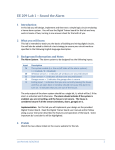
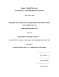
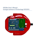
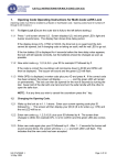
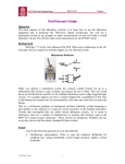
Final Design Project ECE2031 Summer 2011 Final project You have now built an entire computer within the DE2 board Now, we will Put it on a robot, Develop a custom peripheral, and Demonstrate it AmigoBots A commercially-available robot for education Usually used with high-level programming tools For most users (not us), an external PC interfaces through a serial port (usually with wireless adapter) We will discuss three versions 1. The manufactured “original” version 2. The first “AlteraBot,” used for several years in DDL 3. The newest version, where you will be among the first developers The ORIGINAL AmigoBot Features differential-drive 2 drive wheels and motors, rear caster 8 rangefinding sonars (“proximity sensors”) twin 500-tick motor encoders (wheel rotation sensors Hitachi H8S microcontroller dual serial ports 1Mb onboard RAM speaker rechargeable battery Figures from AmigoBot User Manual History of 2031 robot usage Simple robots, similar to textbook chapter 13 (preCollins) AmigoBot purchase, with UP2 boards added as onboard FPGA controller (AlteraBot: 2002) Used for about 15 projects over 20 semesters (2003 – 2009) Now being redesigned in a series of new projects (2010 – 2011+) Why the upgrade? Obvious – better FPGA, more features Less obvious – better system architecture Serial robot-to-FPGA interface was always limiting FPGA did not control robot directly Instructor provided code that implemented a “fake” register-based interface Students wrote SCOMP programs that performed INs and OUTs with I/O registers “Hidden” code took care of details of sending/receiving serial data streams with onboard Hitachi microcontroller Old AlteraBot Architecture • All robot comms went through serial channel • Was not an effective embedded architecture • Robot needed higher communication bandwidth System on (Programmable) Chip Design SOC or SOPC design is the ultimate embedded computing approach A customized computer and customized peripherals all reside on a chip Read textbook (Hamblen et al.) Chapter 15 The old AlteraBot design was a compromise with existing hardware, not a good SOPC design Remaining “base” AmigoBot Features differential-drive 2 drive wheels and motors, rear caster 8 rangefinding sonars (“proximity sensors”) twin 500-tick motor encoders (wheel rotation sensors Hitachi H8S microcontroller dual serial ports 1Mb onboard RAM speaker rechargeable battery Figures from AmigoBot User Manual New AlteraBot Architecture • FPGA (through daughterboard) directly interacts with robot H/W • Very effective embedded architecture • Many potential DDL projects The Fall 2010 project – DONE! • Students focused on measuring wheel rotation (angular position and velocity) • One of the best solutions has now been incorporated into the distribution for future projects The Spring 2011 project – DONE! • Students added the ability to use pulse-width modulation (varying duty cycle) to control motor speed • Again, best student design will be available for future distribution The Summer 2011 project – Sonar • You will add the ability to measure distance to obstacles using sonar • As with last two semesters, the end product is an I/O peripheral for SCOMP Sonar transducers in the Amigobot These sonar transducers are similar to those used in the first Polaroid autofocusing cameras (1970’s) They emit a ping (a “chirp” at 50 kHz, actually) when a high voltage square wave is input across their two terminals This is ultrasonic, but you will hear a click as a side-effect “Ultrasonic ranging” and “sonar ranging” are often used synonomously Transducers produce a small signal when an echo is detected One of 8 transducers How sonar works in the Amigobot The DE2 produces (and receives) only digital signals Internal electronics handle the voltage generation and detection Time delay prior to echo indicates distance to reflecting object Figure shows a generic implementation (our signals described next) T Must ignore this (later) 𝑑 =𝑇 2𝑐 , where d = distance c = speed of sound and T = round-trip delay (c ≈ 340 m/s) Idealized usage of multiple sonars There are 8 transducers, so they have to take turns The echo from one is indistinguishable from another So, before pinging again, wait for the longest possible detectable echo, at least 6 meters: 𝑇𝑚𝑎𝑥 = 2×6 m 340 m/s = 35 ms Example below shows a conservative 50 ms between pings, which you should emulate ECHO0 indicates an object at distance 𝑑 = 0.015 s 2 × 340 m/s = 2.55 m Pings and echoes in Amigobot are actually NOT short pulses like this. Multiplexed implementation of sonar in the Amigobot There is only one “PING” signal for all 8 sonar transducers There is only one “ECHO” signal It is called SONAR_INIT Drive it high to start a ping Keep it high for about 40 ms (and wait 10 ms before next ping) It is called SONAR_ECHO It goes high when an echo is sensed It stays high until SONAR_INIT (above) is lowered The interface electronics use a three-bit signal to control which transducer is “connected” It is called SONAR_SEL[2..0] One more sonar signal… It is necessary to wait before listening for the echo There is an additional signal called SONAR_LISTEN The high energy of a ping creates immediate echo-like noise This is common with sonars (and radars) It dissipates in about 1.2 ms Assert it (drive it high) 1.2 ms after SONAR_INIT De-assert (lower) it simultaneously with SONAR_INIT The 1.2 ms period is also called a blanking interval And the SONAR_LISTEN signal could be called a blanking signal Sonar signal usage Outputs from DE2 Select a sonar transducer with SONAR_SEL (here, changes from 111 to 000) Wait about 5 ms, then assert SONAR_INIT Wait 1.2 ms (blanking interval), then assert SONAR_LISTEN Wait for SONAR_ECHO to be asserted (timing it) After SONAR_INIT has been asserted for 40 ms, de-assert it and SONAR_LISTEN simultaneously Repeat for next sonar Project requirements – I/O Peripheral Create a peripheral for SCOMP that provides sonar data Manage all 8 sonar transducers Drive the SONAR_INIT and SONAR_LISTEN signals Drive the SONAR_SEL[2..0] signals Causing valid pings and listening for echoes Choosing which sonar transducer to use (sequencing between them) Measure time until echoes are returned for each sensor Retain most recent echo data for each sensor Provide data to SCOMP Use I/O address & data buses Respond to requests for latest echo data for each sensor Provide data in known units (time, distance) Project requirements – SCOMP Manage the region of the I/O address space occupied by the sonar device Use a base address 0xA0 and use as many adjacent locations as needed (0xA1, 0xA2,…) Write an SCOMP program that demonstrates your device Display readable sonar readings Interact by moving objects in front of one or more sonar transducers A demo “arena” will be defined that makes it convenient to move objects to known locations Project starting point Start with SCOMP that is provided to you, which includes the following it implements all instructions it has an additional DE2 I/O device working (LCD) it implements an 8-level subroutine call stack it has a minimal (but functional) sonar peripheral Modify as needed, but as a minimum… design your sonar peripheral interface your sonar peripheral to SCOMP develop your demo program Top-level BDF of project files provided Improved I/O Address decoding SCOMP Basic LCD Sonar Sonar region of previous BDF Project development time is short Historically, creating a basic I/O device seems to be a hurdle for students This Sonar device helps by providing basic functionality Pings one transducer & can report echo in ms Basic structure of SONAR.VHD Library, USE, Entity w/ PORT, Declarations, etc. LIBRARY … USE … ENTITY SONAR IS … END SONAR; ARCHITECTURE behavior OF SONAR IS … BEGIN IO_BUS: lpm_bustri … IO_IN <= (CS AND NOT(IO_WRITE)); LATCH <= CS AND IO_WRITE; SONAR_NUM <= "000"; PINGER: PROCESS (CLOCK, RESETN) … INPUT_HANDLER: PROCESS (RESETN, LATCH)… … END behavior; Four main concurrent regions: 1) A fairly familiar tri-state driver 2) Combinational logic 3) This process issues a ping after a PING_START signal and times the return 4) This process could be used to allow host to write values to the device (Note that PROCESS statements can have labels) Schematic interpretation of same 4) This process could be used to allow host to write values to the device 2) Combinational logic 3) This process issues a ping after a PING_START signal and times the return 1) A fairly familiar tri-state driver This schematic does NOT exist in the design, and is provided just to aid in interpretation of the SONAR.VHD Sample waveforms Actual signals from robot shown below Top is DE2-generated INIT (ping starts at rising edge) Bottom is echo Delay is 7.89 ms Project “Decision Space” You can choose how to use I/O locations You can choose how to record echoes (ms, cm, mm) What would a user want? How much accuracy is usable? You can enhance the LCD and 7-segment outputs, as well as use LEDs One 16-bit register? As many as 16 16-bit registers? Some read/write, some read-only, some write-only? Do not consider video output, audio, or other complex DE2 features – you will run out of time You can include special features of your own design (programmability, scaling, etc.) Robot operational details Robots will be permanently located at selected workstations (instead of CADETs) Power switch is on bottom (directly beneath speaker) Red LED is power indicator Please do not move them If it is on, robot is on and it is NOT charging Turn robot off, and make sure charger is plugged in, when not in use Green LED indicates that motor is enabled (more on this later) Yellow LED is not used at this time Black and red pushbuttons are not used at this time When robot has power, DE2 has power, too (you might have to turn on the DE2, using its red button) Project phases and key dates Introductory exercises (July 13-14, in your regular lab section) Investigate project starting point provided for you Brainstorm your approach and turn in proposal on July 18-19 Complete your design Final demonstration – July 27-28 Make a PowerPoint presentation, explaining what worked & what didn’t. Demonstrate your solution. Points for your demo run will factor into your grade. Turn in formal report the following Monday, August 1! (To Instructor Bourgeois by noon!) Project Demo Separate from your oral (PowerPoint) presentation Stand at workstation in defined test arena, showing ease of user interface sonar readings changing as a result of moving objects Project Schedule Sunday Monday Tuesday Wednesday Thursday Friday Saturday July 7 8 Project background in lecture 9 LAB CLOSED You are here 10 LAB CLOSED 11 Finish Lab 8 12 Finish Lab 8 13 Pre-project Exercises & Brainstorming 14 Pre-project Exercises & Brainstorming 15 Presentation and communication tips 16 LAB CLOSED 17 LAB CLOSED 18 Project work 19 Project work 20 Project work 21 Project work 22 Written exam in lecture 23 LAB CLOSED 24 LAB CLOSED 25 Project work 26 Project work 27 Project Demos and presentations 28 Project Demos and presentations 29 Design Report Tips REPORTS DUE MONDAY NOON! 31 LAB CLOSED August 1 Open hours 2 3 4 5 6 Brainstorming / proposal next week Get with your project team (groups of four or five) Use collaborative process described in the “Design Logbook” and other information provided on the UPCP Review these slides and come up with a technical approach and management plan Write proposal in the format described on the UPCP and in the workbook Your proposal will be graded like any other report for style, formatting, content, etc. Your proposal should be detailed! Your proposal should explicitly describe how you plan to implement your sonar device Should describe how it interfaces with SCOMP registers, functions, programmability Again, include relevant figures Should describe your demo SCOMP program Include some figures, such as a state diagram, block diagrams input, output features Again, include a figure such as a flowchart Should describe any unique or advanced features Experiment before proposing! During your first project day in the lab, conduct these activities Investigate the design file template provided Drill down into the details of the devices I/O decoder SCOMP (with 8-level stack, all commands) SONAR (Starting point for your device) Observe sonar waveforms on scope and logic analyzer All of these could be the basis of an exam problem! Thoughts for proposal It is never too early to prototype some ideas for your approach What might be too hard? Assign task responsibilities as you decide what is most interesting to each team member Sonar measurement device Sonar I/O interface SCOMP programming Other unique features Prelab activities (for last Prelab Quiz) Read Chapter 15 of textbook, as noted earlier Study these slides carefully Watch for a posting on the project download page regarding lab activities for first day of project Clarifications You are not responsible for inherent inaccuracies of sonar transducers Your measurements will be compared only to those of other students, demonstrating in the same arena Additional clarifications will be posted on the web site, or as direct answers to email When a general question is asked, everyone gets copied on the response