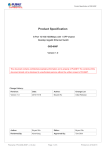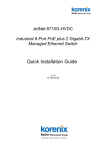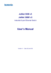
1
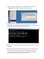
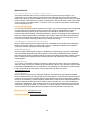
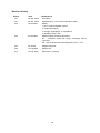
JetCon 2502 Ethernet over VDSL Extender User’s Manual Version: 1.0 Date: 18-Aug, 2009 1 Korenix JetCon 2502 Ethernet over VDSL Extender User’s Manual Copyright Notice Copyright © 2009 Korenix Technology Co., Ltd. All rights reserved. Reproduction in any form or by any means without permission is prohibited. 2 Declaration of CE This product has passed the CE certification for environmental specifications. Test conditions for passing included the equipment being operated within an industrial enclosure. In order to protect the product from being damaged by ESD (Electrostatic Discharge) and EMI leakage, we strongly recommend the use of CE-compliant industrial enclosure products. Federal Communications Commission (FCC) Statement This equipment has been tested and found to comply with the limits for a Class A digital device, pursuant to Part 15 of the FCC Rules. These limits are designed to provide reasonable protection against harmful interference when the equipment is operated in a commercial environment. This equipment generates, uses, and can radiate radio frequency energy and, if not installed and used in accordance with the instruction manual, may cause harmful interference to radio communications. Operation of this equipment in a residential area is likely to cause harmful interference in which case the user will be required to correct the interference at his expense. The user is cautioned that changes and modifications made to the equipment without approval of the manufacturer could void the user's authority to operate this equipment. 3 Key word VDSL: Very High Speed Digital Subscriber Loop VDSL 2: Very High Speed Digital Subscriber Loop version 2 DMT: Discrete Multi-tone modulation STM: Synchronous Transfer mode ASTM : Asynchronous Transfer mode CO : Central office CPE : Customer Premise Equipment QoS: Quality of Service SNR: Signal Noise Ratio INP: Impulse Noise Protection POTS : Plain Old Telephone System AFE : Analog Front End HDTV : High Definition Television FTTC : Fiber to the Corner / cabinet FTTH: Fiber to the Home FTTB: Fiber to the Building 4 Index 1. Introduction..................................................... 1 1-1. Features............................................................ 3 1-2. Package Checklist ............................................ 3 2. Hardware Description..................................... 4 2-1. Dimensions ....................................................... 4 2-2. Hardware Appearance ...................................... 5 2-3. Wiring the DC Power Inputs.............................. 7 2-4. LED Indicators .................................................. 8 3. Mounting Installation ...................................... 9 3-1. DIN-Rail Mounting............................................. 9 3-2. Wall Mounting ................................................. 10 4. System installation and configuration........... 11 4-1. Install and Wiring ............................................ 11 4-2. Dip switch configuration .................................. 12 4-3. VDSL2 Technology ......................................... 13 4-4. Transmission distance and forwarding rate .... 15 4-5. Line impedance of region Telecom Company 16 5. System testing and trouble shooting ............ 20 5-1 .System testing ................................................ 20 5-2. Troubles shooting ........................................... 22 6. Technical Specifications............................... 23 5 1. Introduction This document describes the how to use the Korenix JetCon 2502 Ethernet over VDSL extender, including installation and specifications. Following this user manual, you will be well learned about how to help you construct Network infrastructure with JetCon 2502. The followings are brief introduction of JetCon 2502. Ideal Ethernet /Voice Extender JetCon 2502 is an Ethernet/POTS to VDSL2 (Very High-Rate Digital Subscribe Loop -2) extender and is compliant with ITU-T G.993.2 standard. It allows the VDSL2 carriers to deliver Ethernet data & voice up to 100Mbps in both upstream and downstream over existing twisted copper. The JetCon 2502 Ethernet over VDSL converter features Discrete Multi-Tone modulator/ de-modulator and VDSL Analog Front End (AFE) technology; it is an ideal solution to carry POTS signal (Voice) and Ethernet Data stream to 3000 feet to extend local LAN and voices over the same line. Economical and Simple Connection To deploy VDSL2 access with the telephone network, the VDSL2 converter should follow the line impedance of telephone network. Therefore, each region will adopt different line splitter to provide best communication quality. Therefore, users need additional wiring and splitter, but mostly make a jumble at home or office. The JetCon 2502 has implement splitter for each region to save your installation time. Central and Discrete Internet Access For the network infrastructural, JetCon 2502 is the best choice to plan centralized internet access through the existing POTS wiring system for hotels, dormitories or where need extend LAN over 100m over a single pair of copper wires. Triple Play – HDTV, Data Access, Video conference JetCon 2502 allows users to compete with wireless and satellite providers by offering outstanding service, such as Video conference, HDTV or Video chatting over a existing telephone copper cable without any configuration; just plug and play to enlarge infrastructure for your applications. 1 Internet last mile access The VDSL2 technology also deployed at the last mile of internet access; the ISP uses the fiber cable as backbone uplink to the basement of building (FTTB) or corner of streets (FTTC) and uses the exist 1 pair twisted cable of POTS system to carry voices and Ethernet data stream for user via VDSL2 signal. Intelligent Traffic System application In the Intelligent Traffic system (ITS), the VDSL2 technology could be applied in the long distance data transmission for traffic signal control or traffic information signboard. JetCon 2502 can save the deployment cost of fiber by using the twisted cable up to 3000 feet at DS/US data rate 35Mbps / 8Mbps for low speed data transmission over the Ethernet link distance. Subway & Railway System application JetCon 2502 can also be applied in the subway and railway system to offer long distance transmission with low data traffic; for example, the Fire Alarm System (FAS) and Passenger Information Direction System (PIDS) use the VDSL2 technology to communicate between outdoor device and Control Room to replace the fiber cable and save the cost of deployment 2 1-1. Features IEEE 802.3u 100Base-TX Fast Ethernet Extender IEEE 802.3x flow control & Back-pressure ITU-T G.993.2 VDSL2 standard 2 x RJ-11 connectors for POTS/ISDN and VDSL One RJ-45 10/100Mbps Fast Ethernet Port Build-in POTS/ISDN Splitter Extend Voice and Ethernet to 2KM far Transport 1792 bytes packet size over VDSL2 Broadcast Packet filtering Power input by DC jack & terminal block -25~70℃ Hazardous environment application 1-2. Package Checklist JetCon 2502 package includes the following items: JetCon 2502 x1 DIN-Rail clip x2 CD user manual or Quick installation guide JetCon 2502 User’s Manual CD-ROM Quick Installation Guide Contact your sales representative if any item is missing or damaged. 3 2. Hardware Description 2-1. Dimensions The dimension of JetCon 2502 is 29.6 mm(H) x 88mm (W) x114.8 mm (D) 4 2-2. Hardware Appearance The top view of the JetCon 2502 DIP Switch and power connector show in the following picture, figure 2-2-1. Figure 2-2-1 DIP Switch: For operating mode selection; for the detailed functions please refer chapter 4-2. DC Power Input and Case Grounding Two power inputs with power redundancy with the standard removable terminal block or DC Jack. Power Input Voltage: DC 24V, input range from DC 12 to 48V. Terminal block connector: Center pin: case ground, connects to earth ground for better electric magnetic and static immunity. Right side pin: V+ input. Left side pin: V- input DC Jack: Ø 2mm Center Pin. Center pin is positive voltage. Make sure to use the CE and UL certified AC to DC power adapter or AC to DC switching power supply as a power source. On the other side, there are 1 Fast Ethernet RJ-45 connector and 2 RJ-11 connectors for Line/ISDN and VDSL2. See the following picture, figure 2-2-2. Figure 2-2-2 5 10/100Mbps Fast Ethernet port The fast Ethernet port supports 10/100Mbps link speed with auto-negotiation and auto MDI/MDI-X functions. It integrates 2 LED indicators for Speed and Link/Activity. The meanings of LED explain as below: Speed (Yellow color): Yellow on (100 Mbps link up), Yellow off (no link or 10 Mbps link) Link/Activity (Green color): Green on (link up), Green off (No link), Green blinking (Data is transmitting and receiving) For clear LED indicators of Ethernet port, please refer to the following table. Yellow On (Speed/100Mbps) Yellow Off (Speed/10Mbps) 100 Mbps Link up 10 Mbps Link up. Green blinking 100 Mbps Link up 10 Mbps Link up Green On (Link) (Activity) Green off Data is on Transmitting and Data is on Transmitting and Receiving Receiving Not Available No link Line port (RJ-11): for the PSTN /ISDN line from telecom service center VDSL port (RJ-11): for VDSL 2 communication line. VDSL (Green): indicates the connection status of VDSL. Master (Green): JetCon 2502 operating mode. Power (Green): system power status. 6 2-3. Wiring the DC Power Inputs Follow the steps below to wire JetCon 2502 DC power inputs. [Note] Make sure the Switch Power module or AC/DC power adapter is UL certified. 1. Insert the positive and negative wires into the V+ and V- contacts respectively of the terminal block connector 2. Tighten the wire-clamp screws to prevent the DC wires from being loosened. 3. The terminal block input and DC jack input supports power redundancy. 4. The Chassis Earth Ground must well connect with Earth Ground to provide good electrical magnetic immunity. 7 2-4. LED Indicators There are 2 LEDs on the JetCon 2502 for the Fast Ethernet port, system power and VDSL indications as discussed in the 2-2 Hardware Appearance. More detailed information can be found in the following table. LED Status Description Fast Ethernet Speed (RJ-45) Yellow on Link on 100Mbps Off Link on 10Mbps or no link. Green on The port is link on 10 or 100Mbps Blinking The port is on transmitting/receiving data. Off There is no device attached. Fast Ethernet Link/Activity (RJ-45) Green Fast No VDSL device attached. Blinking VDSL Master Green Slow Blinking On negotiate with other VDSL device Green On VDSL communication is ready Green on Ethernet/VDSL Extender is working on Master mode. Green off Ethernet/VDSL Extender is working on Slave mode. (Default setting) Green on The power is applied. Blinking No power. Power 8 3. Mounting Installation 3-1. DIN-Rail Mounting The DIN-Rail clip is attached in the box; there are 2 clips with 4 screws. The clip supports EN 50022 rail; screw on the clips to the wall mount ears before installing JetCon 2502 to the rail. Refer to the diagram 3-1- 1. After screwing on the clip, follow the steps below to mount the JetCon 2502 Figure 3-1-1 to the standard DIN-Rail. . 1. Insert the upper end of the DIN-Rail clip into the back of the DIN-Rail track from its upper side 2. Slightly press the bottom of the DIN-Rail clip into the track. 3. Check if the DIN-Rail clip is tightly attached to the track. 4. To remove JetCon 2502 from the track, use a flat screw driver to loosen the clip from rail track. See the diagram 3-1-2. Figure 3-1-2 9 3-2. Wall Mounting JetCon 2502 can be wall mounted through the wall mount hole. Please refer to the figure- 3-2-1. Figure 3-2-1 10 4. System installation and configuration This session will introduce how to install and configure JetCon 2502 Ethernet over VDSL Extender and also introduce VDSL2 technology according to the following sequences. 4-1. Install and wire 4-2. DIP Switch configuration 4-3. VDSL2 Technology 4-4. Available transmission distance and rate 4-5. Line impedance of region Telecom Company 4-1. Install and Wiring JetCon 2502 is an Ethernet over VDSL Extender which adopted 2 RJ-11 connectors for the connection of Line and VDSL communication; the Ethernet supports RJ-45 for 10/100Mbps. About the connectors, please refer to figure 2-2-2 in chapter 2.2. In figure 4-1-1, the architecture uses traditional 1 pair twisted cable between central office (CO site) and remote (CPE site) to achieve data and voice communication over VDSL 2 technology without wire reconstruction. Figure 4-1-1 11 Connecting the communication port CO (Central office) site: The RJ-11 port (Line) on the CO site should connect to voice network – (PSTN); JetCon 2502 will modulate voice and Ethernet signal into VDSL-2 signal and forward to CPE site by paired twisted cable through RJ-11 (VDSL-2 ) connector. During the communication, the LED will activate as different operating status. Please refer to chapter 2-2 for LED description. CPE (Customer premise equipment) site: the remote CPE site is the same as CO site; the line port is connected to a POTS Phone and provides voice communication. 4-2. Dip switch configuration JetCon 2502 provides 4 DIP switches for system configuration; each DIP switch has independent function. Please refer to the following description. DIP Switch -1: Mode selection. Master mode (On): Acts as Central office (master). Slave mode (Off): Acts as remote office (slave). Each JetCon 2502’s mode should correspond to central (master) or remote (slave) installation. The default setting is slave mode (off) DIP Switch-2: Impulse Protection. The impulse protection can deliver better communication quality under 250ms duration of noise when configuring this function; the stream will have longer forwarding latency. On: Interleave mode with six ms forwarding latency time. Off: Fast mode with one ms forwarding latency time. DIP Switch-3: Symmetric. Symmetric mode (Off): Upstream and downstream with same data forwarding rate. The default setting is “Off”. Asymmetric mode (On): Upstream and downstream with different data forwarding rate. DIP Switch-4: SNR (Signal to Noise Ratio) SNR (On): Better channel noise protection with SNR up to 9 dB. SNR (Off): Original channel noise protection with 6 dB SNR. (Default setting) Activate these functions when JetCon 2502 is allocated or installed in environments with huge electric static or electric magnetic interferences. 12 4-3. VDSL2 Technology The VDSL (Very High Bit-rate Digital Subscriber Line) is a DSL technology providing faster data transmission over a single flat untwisted or twisted pair of copper wires. These fast speeds mean that VDSL is capable of supporting high bandwidth applications such as HDTV, as well as telephone services (Voice over IP) and general Internet access, over a single connection. VDSL is deployed over existing wiring used for POTS (Plain Old Telephone Service) and lower-speed DSL connections. This VDSL standard ITU G.993.1 was approved and released in November 2001. The VDSL2 is second generation of VDSL and standardized as ITU-T G.993.2 in Feb, 2006. It is an access technology that exploits the existing infrastructure of copper wiring network originally deployed for POTS services. It can be deployed from central offices, from fiber-end cabinets that located near the customer premises, or within buildings for the last mile access of FTTB (Fiber to the building), FTTH (Fiber to the home) or FTTC (Fiber to the corner, cabinet). The VDSL 2 technology is the newest and advanced technology that deploys on the copper wires to support triple play services, such as voice, data, high definition television (HDTV) and interactive games. The VDSL 2 has defined 3 band planes- Annex A for North-American, Annex B for Europe and Annex C for Japan. Band plan is defined as the following frequency spectrum diagram. Annex A, North American Annex B, Europe, 997 symmetric band plan 13 Annex B, Europe, 998 asymmetric band plan Annex C, Japan The VDSL2 standard ITU-T G.993.2 also specify eight types of transmission profile for each band plan. Characteristics VDSL 2 Profile 8a 8b 8c 8d 12a 12b 17a 30a Bandwidth (MHz) 8.832 8.832 8.5 8.832 12 12 17.664 30 Carrier bandwidth (KHz) 4.3125 4.3125 4.3125 4.3125 4.3125 4.3125 4.3125 8.625 US0 channel support Yes Yes Yes Yes Yes No DS power (dBm) (min) +17.5 +20.5 +11.5 +14.5 +14.5 +14.5 50 50 50 50 68 68 Maximum Throughput (Mbit/s) No +14.5 +14.5 100 The JetCon 2502 supports 17a profile with 100Mbits forwarding rate in 997 symmetric band plan; the following figure shows the bandwidth utilization of JetCon 2502. 14 No 200 4-4. Transmission distance and forwarding rate With the un-shielding twisted cable, JetCon 2502 extends the distance of voice and Ethernet Data to 8,000 feet. For relevant distance and rate, please refer to the following table. JetCon 2502, Fast mode, without noise, SNR 6dB 26AWG Twisted pair cable Cable Length Feet Meter 0 0 Line Rate (Kb) US DS 99,104 90,144 Data Rate (Kb) US DS 89,088 81,024 1,000 303 72,736 77,760 65,344 69,888 2,000 606 31,904 41,728 28,608 37,440 3,000 909 14,784 24,576 13,184 22,016 4,000 1,212 6,016 18,240 5,312 16,320 5,000 1,515 1,120 17,696 896 15,808 6,000 1,818 896 11,584 704 10,304 7,000 2,121 768 6,528 576 5,760 8,000 2,424 608 4,544 448 3,968 US: Up Stream DS:Down Stream 15 4-5. Line impedance of region Telecom Company To deploy voice into communication system, JetCon 2502 has adopted a line splitter to correspond to the line impedance of subscriber provider. Therefore, JetCon 2502 adopted suitable splitter for different region. Therefore, customers do not need to install extra line splitter for simple wiring; just plug and play. The following table indicates the line impedance by country for your reference. . Territory/Country CPE/ Microfilter Application Line impedance Argentina Microfilter POTS Zcomplex-270 Argentina Microfilter POTS Zcomplex-270 Australia Microfilter POTS 600 ohms Australia CPE POTS Zcomplex-270/Option A Austria Microfilter POTS 600 ohms Belgium Microfilter POTS 600 ohms Belgium Microfilter POTS 600 ohms Brazil Microfilter POTS 600 ohms Brazil CPE POTS 600 ohms Bulgaria CPE POTS Zcomplex-220 Chile Microfilter POTS 600 ohms Chile Microfilter POTS 600 ohms China CPE POTS 600 ohms Colombia Microfilter POTS 600 ohms Colombia CPE POTS 600 ohms Costa Rica Microfilter POTS 600 ohms Costa Rica CPE POTS 600 ohms Croatia CPE VDSL/ISDN & POTS Cyprus CPE POTS Czech CPE VDSL/ISDN & POTS Denmark CPE POTS Zcomplex-270/OPTION A Denmark CPE POTS Zcomplex-270/OPTION A Denmark CPE 2B1Q/4B3T/POTS 600 ohms 2B1Q/4B3T/POTS VDSL/ISDN & POTS 2B1Q/4B3T/POTS Egypt Microfilter POTS 600 ohms Egypt CPE POTS 600 ohms Microfilter POTS 600 ohms Estonia 16 Estonia CPE POTS 600 ohms Finland Microfilter POTS 600 ohms Finland CPE POTS Zcomplex-270/Option A France Microfilter POTS Zcomplex-270 Germany CPE VDSL/POTS Zcomplex-220 Germany CPE VDSL/ISDN & POTS 2B1Q/4B3T/220 Greece Microfilter POTS 600 ohms Greece CPE POTS 600 ohms Greece CPE ISDN & POTS 2B1Q/4B3T/POTS Hungary CPE ISDN & POTS 2B1Q/4B3T/POTS Iceland( CPE POTS Zcomplex-270/OPTION A India( Microfilter POTS 600 ohms India CPE POTS 600 ohms Ireland Microfilter POTS 600 ohms Ireland CPE POTS Zcomplex-270/OPTION A Israel Microfilter POTS 600 ohms Israel Microfilter POTS 600 ohms Italy Microfilter POTS 600 ohms Italy Microfilter POTS Zcomplex-270 Italy( CPE POTS Zcomplex-270/OPTION A Latin America Microfilter POTS 600 ohms Latin America CPE POTS 600 ohms Latvia CPE POTS Zcomplex-270/OPTION A Lebanon Microfilter POTS 600 ohms Lebanon CPE POTS Zcomplex-270/OPTION A Lithuania Microfilter POTS 600 ohms Lithuania CPE POTS 600 ohms Luxembourg Microfilter POTS 600 ohms Luxembourg CPE POTS 600 ohms Malaysia Microfilter POTS 600 ohms Malaysia CPE POTS 600 ohms Malta Microfilter POTS 600 ohms Malta CPE POTS 600 ohms Netherland CPE ISDN & POTS Netherland CPE POTS 17 2B1Q/4B3T/POTS Zcomplex-270/OPTION A New Zealand CPE POTS Zcomplex-370 Nicaragua Microfilter POTS 600 ohms Nicaragua CPE POTS 600 ohms North America CPE POTS 600 ohms Norway CPE ISDN & POTS Pakistan Microfilter POTS 600 ohms Peru Microfilter POTS 600 ohms Peru Microfilter POTS 600 ohms Philippines Microfilter POTS 600 ohms Philippines CPE POTS 600 ohms Poland Microfilter POTS 600 ohms Poland CPE POTS 600 ohms Portugal Microfilter POTS 600 ohms Portugal Microfilter POTS 600 ohms Portugal CPE ISDN & POTS Romania Microfilter POTS Zcomplex-270 Romania CPE POTS Zcomplex-270/OPTION B Romania CPE ISDN Russia Microfilter POTS Russia CPE ISDN & POTS Russia CPE POTS 600 ohms Singapore Microfilter POTS 600 ohms Singapore CPE POTS 600 ohms Slovakia Microfilter POTS 600 ohms Slovakia CPE ISDN & POTS Slovakia CPE POTS 600 ohms Souther Africa CPE POTS Zcomplex-270/OPTION A Spain Microfilter POTS 600 ohms Spain CPE POTS 600 ohms Sweden CPE POTS Zcomplex-270 Switzerland CPE ISDN & POTS Switzerland Microfilter POTS Zcomplex-270 Switzerland CPE POTS Zcomplex-270/OPTION A/B Switzerland CPE POTS Zcomplex-270/OPTION A Taiwan Microfilter POTS 600 ohms Taiwan CPE POTS 600 ohms Microfilter POTS 600 ohms Thailand 18 2B1Q/4B3T/POTS 2B1Q/4B3T/POTS 2B1Q/4B3T/POTS 600 ohms 2B1Q/4B3T/POTS 2B1Q/4B3T/POTS 2B1Q/4B3T/270 Thailand CPE POTS 600 ohms Turkey Microfilter POTS 600 ohms Turkey CPE POTS 600 ohms United Kingdom Microfilter POTS Zcomplex-320 United Kingdom Microfilter POTS Zcomplex-320 United Kingdom Microfilter POTS 600 ohms United Kingdom CPE POTS Zcomplex-320 Uruguay Microfilter POTS 600 ohms Uruguay CPE POTS 600 ohms Venezuela Microfilter POTS 600 ohms Vietnam Microfilter POTS 600 ohms Vietnam CPE POTS 600 ohms Make sure that the line impedance model of JetCon 2502 is compliant with your region’s subscriber provider. If the line impedance is not matched, it may cause poor communication quality. Otherwise the application is only for the Ethernet port extension without voice communication. 19 5. System testing and trouble shooting 5-1 .System testing 1. Take out two JetCon 2502 from the package box; one emulate CO site (local), and the other one is CPE site (remote). 2. Apply the power into JetCon 2502 and check the power LED status to make sure JetCon 2502 is ready. 3. Set the mode selection dip switch to “on” to enable master function on JetCon 2502 in the local site; the JetCon 2502 in the remote site should be off. 4. Connect PC to the 10/100Mbps RJ-45 connector of both JetCon 2502 with standardized Ethernet cable. 5. Plug in RJ-11 connector of phone line into Line port of JetCon 2502 in the local site. 6. Connect the VDSL2 ports of two JetCon 2502 by one pair UTP cable and check the VDSL LED status to make sure the VDSL connection is ready. Please refer to the chapter 2-4 LED. 7. Connect a POTS phone to the line port of JetCon 2502 in the remote site. 8. Check the LED Ethernet port of both sites are ready. For wiring architecture, please refer to the diagram below. 20 9. Enable “Command Line mode” of PC, click Run in the Start menu, type Command, and click OK to continue as the picture indicates. 10. Type ping 192.168.1.1 command to check the connection. Here we use IP address 192.168.1.1 as an example. Before testing, be sure your two PC hosts in the local site and remote site are in the same IP subnet. 11. Repeat step 10 to make sure the Ethernet connection of both sites is successfully established. 12. Pick up the remote-site POTS phone and check the dial tone is heard from the phone receiver to ensure the Public Switched Telephone Networks has recognized that a phone has gone off-hook; and the switching equipment is prepared to receive the dialed digital tone or DTMF code. 21 13. Try to dial a phone number to establish a voice connection to make sure the voices are clear. 14. If the data or voice communication cannot establish, please contact Korenix local dealer or distributor for further assistance. 5-2. Troubles shooting Make sure you use the correct DC power suppliers (DC12~ 48 V) or power adapters. Select Ethernet cables with specifications suitable for your applications to set up your systems. Ethernet cables are categorized into unshielded twisted-pair (UTP) and shielded twisted-pair (STP) cables. Category 3 Ethernet cables are suitable for systems with 10 Mbps transmission speed. For systems with 100Mbps transmission speed, Category 4, 5 Ethernet cables are the only suitable specifications for this environment. Also make sure that the distance between each node cannot be longer than 100 meters (328 feet). If the power LEDs goes off as the power cord plugged in, a power failure might occur. Check the power output connection to see if there is any error at the power source. If you still cannot solve the problem, contact your local dealer for assistance 22 6. Technical Specifications Technology Standard IEEE 802.3 10Base-T IEEE 802.3u 100Base-T IEEE 802.1p Class of Service IEEE 802.1Q Quality of Service ITU-T G.993.2 VDSL2 Performance Forwarding Technology Store and Forward technology with 64 ~1792 bytes packet forwarding ability. Switch Packet buffer 384Kbits MAC Table 2K with 300 Sec agent time Class of Service 4 Packet forwarding queues with 1 (Lowest):4 (Low):8 (High):15 (Highest) WRR (weighted round robin) forwarding schematics Quality of Service VLAN tag priority, IPv4 packet precedence and IPv6 ToS. Broadcast filtering Fast Ethernet: 200 packet / per sec. @ 100Mbps; 20 packet / per sec. @ 10Mbps Interface Number of Ports 1 x 10/100Mbps Fast Ethernet port with Auto MDI/MDI-X function, Auto-Negotiation 1 x Line for ISDN/POTS 1 x VDSL2 port Connectors Cables Configuration DIP Switch Diagnostic LED 10/100 Base-TX: RJ-45 with auto MDI/MDI-X, Auto negotiation ISDN/POTS: RJ-11 VDSL 2: RJ-11 RJ-45 Fast Ethernet port: Cat. 4,5 2 pairs UTP cable, up to 100 meters VDSL2: 1 pairs of UTP cable, up to 3000 feet. Line: Integrated ISDN/POTS. DIP-1(Mode selection): On (Master)/Off (Slave) DIP-2(Impulse protection): On (Interleave)/ Off (Fast); Interleave mode with less than 250ms forwarding latency, Fast mode is less than 2 ms forwarding latency. DIP-3(Rate Control): On (Non-Symmetric)/Off (Symmetric) DIP-4(SNR Control): On (6dB) /Off (9dB) System Power: Power on (Green On) Fast Ethernet port: Speed (100Mbps: Yellow On), Link/ Activity (Green) (On: 10 or 100Mbps Link up, Blinking: packet is on transmitting) Master (Green on): Device operating under Master Mode. VDSL Link/Negotiation (Green): On/ Link, Blinking/Negotiation Power Requirements System Power Power Consumption DC jack: 12~48V, 3-Pin, Ø 2mm Center Pin Terminal block: DC 12~48V, 3-Pin terminal block with earth ground. Power input with polarity reverse protection. 5 Watts @ DC 24V(Maximum) 23 Mechanical Installation Wall mount or DIN Rail mount Case Aluminum metal case Dimension 29mm(H) x 88mm (W) x114 mm (D) Weight g with package g without package Environmental Operating Temperature -40℃ ~70℃ Operating Humidity 0% ~ 95% non-condensing Storage Temperature -40℃ ~ 80 ℃ Storage Humidity 0%~ 95% non-condensing Regulatory Approvals Hi-Pot AC 1.5KV for Ethernet port to power, port to case. EMI FCC class A, CE/EN55022 class A EMC immunity interface Shock IEC61000-4-2 , IEC61000-4-3, IEC61000-4-4, IEC61000-4-5, IEC61000-4-6, IEC61000-4-8 IEC60068-2-27 Vibration IEC60068-2-6 Free Fall IEC60068-2-32 MTBF , MIL-HDBK-217F 24 About Korenix Less Time At Work! Fewer Budget on applications! The Korenix business idea is to let you spend less time at work and fewer budget on your applications. Do you really want to go through all the troubles but still end up with low quality products and lousy services? Definitely not! This is why you need Korenix. Korenix offers complete product selection that fulfills all your needs for applications. We provide easier, faster, tailor-made services, and more reliable solutions. In Korenix, there is no need to compromise. Korenix takes care of everything for you! Fusion of Outstandings You can end your searching here. Korenix Technology is your one-stop supply center for industrial communications and networking products. Korenix Technology is established by a group of professionals with more than 10 year experience in the arenas of industrial control, data communications and industrial networking applications. Korenix Technology is well-positioned to fulfill your needs and demands by providing a great variety of tailor-made products and services. Korenix’s industrial-grade products also come with quality services. No more searching, and no more worries. Korenix Technology stands by you all the way through. Core Strength---Competitive Price and Quality With our work experience and in-depth know-how of industrial communications and networking, Korenix Technology is able to combine Asia’s research / development ability with competitive production cost and with quality service and support. Global Sales Strategy Korenix’s global sales strategy focuses on establishing and developing trustworthy relationships with value added distributors and channel partners, and assisting OEM distributors to promote their own brands. Korenix supplies products to match local market requirements of design, quality, sales, marketing and customer services, allowing Korenix and distributors to create and enjoy profits together. Quality Services KoreCARE--- KoreCARE is Korenix Technology’s global service center, where our professional staffs are ready to solve your problems at any time and in real-time. All of Korenix’s products have passed ISO-9000/EMI/CE/FCC/UL certifications, fully satisfying your demands for product quality under critical industrial environments. Korenix global service center’s e-mail is [email protected] 5 Years Warranty Each of Korenix’s product line is designed, produced, and tested with high industrial standard. Korenix warrants that the Product(s) shall be free from defects in materials and workmanship for a period of five (5) years from the date of delivery provided that the Product was properly installed and used. This warranty is voided if defects, malfunctions or failures of the warranted Product are caused by damage resulting from force measure (such as floods, fire, etc.), environmental and atmospheric disturbances, other external forces such as power line disturbances, host computer malfunction, plugging the board in under power, or incorrect cabling; or the warranted Product is misused, abused, or operated, altered and repaired in an unauthorized or improper way Business service : [email protected] Customer service: [email protected] 25 Revision History Edition Date Modifications V0.1 25, Mar, 2009 first edition V0.1 30, Mar, 2009 Modify territory / country line impendence table. V0.2 16-Apr,2009 Modify 1.ITU-T G.993.2 standard number. 2. Product description. 3. Change “impendence” to “impedance”. 4. Operating Temp: -40C V0.3 23-Apr,2009 Modify impulse protection description On – interleave mode with longer forwarding latency time-6ms. Off – fast mode with fast forwarding latency time – 1ms. V0.4 29-Jun-09 English read proof V0.5 14-Aug,2009 Modify LED. V1.0 18-Aug, 2009 Approved by I-Testing. 26