1
User Manual
HFS 9000
Stimulus System
070-8365-03
Please check for change information
at the rear of this manual.
Copyright Tektronix, Inc. 1994. All rights reserved.
Tektronix products are covered by U.S. and foreign patents, issued and pending. Information in this publication supercedes
that in all previously published material. Specifications and price change privileges reserved.
Printed in the U.S.A.
Tektronix, Inc., P.O. Box 1000, Wilsonville, OR 97070–1000
TEKTRONIX and TEK are registered trademarks of Tektronix, Inc.
WARRANTY
Tektronix warrants that this product will be free from defects in materials and workmanship for a period of one (1)
year from the date of shipment. If any such product proves defective during this warranty period, Tektronix, at its
option, either will repair the defective product without charge for parts and labor, or will provide a replacement in
exchange for the defective product.
In order to obtain service under this warranty, Customer must notify Tektronix of the defect before the expiration
of the warranty period and make suitable arrangements for the performance of service. Customer shall be
responsible for packaging and shipping the defective product to the service center designated by Tektronix, with
shipping charges prepaid. Tektronix shall pay for the return of the product to Customer if the shipment is to a
location within the country in which the Tektronix service center is located. Customer shall be responsible for
paying all shipping charges, duties, taxes, and any other charges for products returned to any other locations.
This warranty shall not apply to any defect, failure or damage caused by improper use or improper or inadequate
maintenance and care. Tektronix shall not be obligated to furnish service under this warranty a) to repair damage
resulting from attempts by personnel other than Tektronix representatives to install, repair or service the product;
b) to repair damage resulting from improper use or connection to incompatible equipment; or c) to service a
product that has been modified or integrated with other products when the effect of such modification or
integration increases the time or difficulty of servicing the product.
THIS WARRANTY IS GIVEN BY TEKTRONIX WITH RESPECT TO THIS PRODUCT IN LIEU OF
ANY OTHER WARRANTIES, EXPRESSED OR IMPLIED. TEKTRONIX AND ITS VENDORS
DISCLAIM ANY IMPLIED WARRANTIES OF MERCHANTABILITY OR FITNESS FOR A
PARTICULAR PURPOSE. TEKTRONIX’ RESPONSIBILITY TO REPAIR OR REPLACE DEFECTIVE
PRODUCTS IS THE SOLE AND EXCLUSIVE REMEDY PROVIDED TO THE CUSTOMER FOR
BREACH OF THIS WARRANTY. TEKTRONIX AND ITS VENDORS WILL NOT BE LIABLE FOR ANY
INDIRECT, SPECIAL, INCIDENTAL, OR CONSEQUENTIAL DAMAGES IRRESPECTIVE OF
WHETHER TEKTRONIX OR THE VENDOR HAS ADVANCE NOTICE OF THE POSSIBILITY OF
SUCH DAMAGES.
Table of Contents
General Safety Summary . . . . . . . . . . . . . . . . . . . . . . . . . . . . . . . . . . . .
Preface . . . . . . . . . . . . . . . . . . . . . . . . . . . . . . . . . . . . . . . . . . . . . . . . . . .
xi
xv
Getting Started
Product Description . . . . . . . . . . . . . . . . . . . . . . . . . . . . . . . . . . . . . . . . . . . . . . .
A Brief Tour . . . . . . . . . . . . . . . . . . . . . . . . . . . . . . . . . . . . . . . . . . . . . . . . . . . . .
Part 1: Reset the HFS 9000 . . . . . . . . . . . . . . . . . . . . . . . . . . . . . . . . . . . . . .
Part 2: Set the Time Base . . . . . . . . . . . . . . . . . . . . . . . . . . . . . . . . . . . . . . .
Part 3: Turn On Pulse Output . . . . . . . . . . . . . . . . . . . . . . . . . . . . . . . . . . . .
Part 4: Setting Up a Data Time Generator . . . . . . . . . . . . . . . . . . . . . . . . . .
1–1
1–2
1–2
1–6
1–10
1–11
An Operator Overview . . . . . . . . . . . . . . . . . . . . . . . . . . . . . . . . . . . . . .
Calibration . . . . . . . . . . . . . . . . . . . . . . . . . . . . . . . . . . . . . . . . . . . . . . . .
Channels . . . . . . . . . . . . . . . . . . . . . . . . . . . . . . . . . . . . . . . . . . . . . . . . . .
Data Time Generators . . . . . . . . . . . . . . . . . . . . . . . . . . . . . . . . . . . . . . .
Deskew . . . . . . . . . . . . . . . . . . . . . . . . . . . . . . . . . . . . . . . . . . . . . . . . . . .
GPIB . . . . . . . . . . . . . . . . . . . . . . . . . . . . . . . . . . . . . . . . . . . . . . . . . . . . .
Levels . . . . . . . . . . . . . . . . . . . . . . . . . . . . . . . . . . . . . . . . . . . . . . . . . . . .
Phase Lock . . . . . . . . . . . . . . . . . . . . . . . . . . . . . . . . . . . . . . . . . . . . . . . .
Power On . . . . . . . . . . . . . . . . . . . . . . . . . . . . . . . . . . . . . . . . . . . . . . . . .
Pulse Generators . . . . . . . . . . . . . . . . . . . . . . . . . . . . . . . . . . . . . . . . . . .
Reset . . . . . . . . . . . . . . . . . . . . . . . . . . . . . . . . . . . . . . . . . . . . . . . . . . . . .
RS-232-C . . . . . . . . . . . . . . . . . . . . . . . . . . . . . . . . . . . . . . . . . . . . . . . . .
Saved Settings . . . . . . . . . . . . . . . . . . . . . . . . . . . . . . . . . . . . . . . . . . . . .
Self Test . . . . . . . . . . . . . . . . . . . . . . . . . . . . . . . . . . . . . . . . . . . . . . . . . . .
Time Base . . . . . . . . . . . . . . . . . . . . . . . . . . . . . . . . . . . . . . . . . . . . . . . . .
Trigger . . . . . . . . . . . . . . . . . . . . . . . . . . . . . . . . . . . . . . . . . . . . . . . . . . .
2–1
2–7
2–9
2–13
2–25
2–29
2–35
2–39
2–43
2–45
2–51
2–53
2–57
2–59
2–61
2–67
Setting Up the Instrument . . . . . . . . . . . . . . . . . . . . . . . . . . . . . . . . . . .
3–1
Controllers . . . . . . . . . . . . . . . . . . . . . . . . . . . . . . . . . . . . . . . . . . . . . . . . . . . . . .
Using the GPIB Interface . . . . . . . . . . . . . . . . . . . . . . . . . . . . . . . . . . . . . . . . . . .
3–1
3–1
Command Syntax . . . . . . . . . . . . . . . . . . . . . . . . . . . . . . . . . . . . . . . . . .
3–9
Clearing the HFS 9000 . . . . . . . . . . . . . . . . . . . . . . . . . . . . . . . . . . . . . . . . . . . . .
Command and Query Structure . . . . . . . . . . . . . . . . . . . . . . . . . . . . . . . . . . . . . .
Command Entry . . . . . . . . . . . . . . . . . . . . . . . . . . . . . . . . . . . . . . . . . . . . . . . . . .
Argument Types . . . . . . . . . . . . . . . . . . . . . . . . . . . . . . . . . . . . . . . . . . . . . . . . . .
Data Formats . . . . . . . . . . . . . . . . . . . . . . . . . . . . . . . . . . . . . . . . . . . . . . . . . . . .
3–9
3–9
3–11
3–13
3–19
Operating Basics
Reference
HFS 9000 User Manual
i
Table of Contents
Syntax Diagrams . . . . . . . . . . . . . . . . . . . . . . . . . . . . . . . . . . . . . . . . . . . . . . . . .
3–20
Commands . . . . . . . . . . . . . . . . . . . . . . . . . . . . . . . . . . . . . . . . . . . . . . . .
Status and Events . . . . . . . . . . . . . . . . . . . . . . . . . . . . . . . . . . . . . . . . . .
3–21
3–129
Registers . . . . . . . . . . . . . . . . . . . . . . . . . . . . . . . . . . . . . . . . . . . . . . . . . . . . . . . .
Queues . . . . . . . . . . . . . . . . . . . . . . . . . . . . . . . . . . . . . . . . . . . . . . . . . . . . . . . . .
Event Handling Sequence . . . . . . . . . . . . . . . . . . . . . . . . . . . . . . . . . . . . . . . . . .
Conflicts . . . . . . . . . . . . . . . . . . . . . . . . . . . . . . . . . . . . . . . . . . . . . . . . . . . . . . . .
Messages . . . . . . . . . . . . . . . . . . . . . . . . . . . . . . . . . . . . . . . . . . . . . . . . . . . . . . .
3–129
3–133
3–133
3–134
3–135
Programming Examples . . . . . . . . . . . . . . . . . . . . . . . . . . . . . . . . . . . . .
3–139
Example 1: Setting Up a Pulse Channel . . . . . . . . . . . . . . . . . . . . . . . . . . . . . . .
Example 2: Command/Query Usage with Error Handling . . . . . . . . . . . . . . . . .
Example 3: Interacting With a User . . . . . . . . . . . . . . . . . . . . . . . . . . . . . . . . . . .
3–139
3–141
3–144
Appendix A: Accessories . . . . . . . . . . . . . . . . . . . . . . . . . . . . . . . . . . . . .
A–1
Standard Accessories . . . . . . . . . . . . . . . . . . . . . . . . . . . . . . . . . . . . . . . . . . . . . .
Optional Accessories . . . . . . . . . . . . . . . . . . . . . . . . . . . . . . . . . . . . . . . . . . . . . .
Power Cord Options . . . . . . . . . . . . . . . . . . . . . . . . . . . . . . . . . . . . . . . . . . . . . . .
A–1
A–2
A–2
Appendix B: Specifications . . . . . . . . . . . . . . . . . . . . . . . . . . . . . . . . . . .
B–1
Nominal Traits . . . . . . . . . . . . . . . . . . . . . . . . . . . . . . . . . . . . . . . . . . . . . . . . . . .
Warranted Characteristics . . . . . . . . . . . . . . . . . . . . . . . . . . . . . . . . . . . . . . . . . .
Typical Characteristics . . . . . . . . . . . . . . . . . . . . . . . . . . . . . . . . . . . . . . . . . . . . .
B–1
B–8
B–11
Appendix C: Interface Specifications . . . . . . . . . . . . . . . . . . . . . . . . . .
C–1
Interface Messages . . . . . . . . . . . . . . . . . . . . . . . . . . . . . . . . . . . . . . . . . . . . . . . .
Character Set (ASCII Chart) . . . . . . . . . . . . . . . . . . . . . . . . . . . . . . . . . . . . . . . .
Reserved Words . . . . . . . . . . . . . . . . . . . . . . . . . . . . . . . . . . . . . . . . . . . . . . . . . .
Using Debug Mode . . . . . . . . . . . . . . . . . . . . . . . . . . . . . . . . . . . . . . . . . . . . . . .
GPIB Function Subsets . . . . . . . . . . . . . . . . . . . . . . . . . . . . . . . . . . . . . . . . . . . .
Wiring for Alternate RS-232-C Configurations . . . . . . . . . . . . . . . . . . . . . . . . . .
C–1
C–2
C–3
C–4
C–5
C–6
Appendix D: Error Messages . . . . . . . . . . . . . . . . . . . . . . . . . . . . . . . . .
Appendix E: Packing for Shipment . . . . . . . . . . . . . . . . . . . . . . . . . . . .
Appendix F: Performance Verification . . . . . . . . . . . . . . . . . . . . . . . . .
D–1
E–1
F–1
Required Test Equipment . . . . . . . . . . . . . . . . . . . . . . . . . . . . . . . . . . . . . . . . . . .
Test Record . . . . . . . . . . . . . . . . . . . . . . . . . . . . . . . . . . . . . . . . . . . . . . . . . . . . . .
Verification Sequence . . . . . . . . . . . . . . . . . . . . . . . . . . . . . . . . . . . . . . . . . . . . . .
Self Test . . . . . . . . . . . . . . . . . . . . . . . . . . . . . . . . . . . . . . . . . . . . . . . . . . . .
Calibration . . . . . . . . . . . . . . . . . . . . . . . . . . . . . . . . . . . . . . . . . . . . . . . . . . .
Check Procedures . . . . . . . . . . . . . . . . . . . . . . . . . . . . . . . . . . . . . . . . . . . . . . . . .
F–1
F–2
F–11
F–11
F–12
F–13
Appendices
ii
HFS 9000 User Manual
Table of Contents
Instrument Setup . . . . . . . . . . . . . . . . . . . . . . . . . . . . . . . . . . . . . . . . . . . . . .
Output Level Checks (HFS 9DG1 Card Only) . . . . . . . . . . . . . . . . . . . . . . .
Output Level Checks (HFS 9DG2 and HFS 9PG2 Cards Only) . . . . . . . . .
Output Level Checks (HFS 9PG1 Card Only) . . . . . . . . . . . . . . . . . . . . . . .
Trigger Output Level . . . . . . . . . . . . . . . . . . . . . . . . . . . . . . . . . . . . . . . . . .
Rise Time and Fall Time Checks (HFS 9PG1 and HFS 9DG1 Cards Only)
Rise Time and Fall Time Checks (HFS 9PG2 and HFS 9DG2 Cards Only)
Edge Placement Checks . . . . . . . . . . . . . . . . . . . . . . . . . . . . . . . . . . . . . . . .
Frequency Accuracy Check . . . . . . . . . . . . . . . . . . . . . . . . . . . . . . . . . . . . .
Phase Lock Check . . . . . . . . . . . . . . . . . . . . . . . . . . . . . . . . . . . . . . . . . . . . .
F–13
F–13
F–16
F–19
F–21
F–22
F–25
F–27
F–31
F–34
Glossary
Index
HFS 9000 User Manual
iii
Table of Contents
List of Figures
iv
Figure 1–1: MAIN MENU Button Location . . . . . . . . . . . . . . . . . . . . .
Figure 1–2: Main Menu Display . . . . . . . . . . . . . . . . . . . . . . . . . . . . . .
Figure 1–3: The SELECT and Arrow Buttons . . . . . . . . . . . . . . . . . . .
Figure 1–4: The Save/Recall Menu . . . . . . . . . . . . . . . . . . . . . . . . . . . .
Figure 1–5: The Reset Verification Dialog . . . . . . . . . . . . . . . . . . . . . .
Figure 1–6: The Time Base Menu . . . . . . . . . . . . . . . . . . . . . . . . . . . . .
Figure 1–7: Time Base Relationships . . . . . . . . . . . . . . . . . . . . . . . . . . .
Figure 1–8: Mode Set to Auto-Burst . . . . . . . . . . . . . . . . . . . . . . . . . . .
Figure 1–9: The Time Base Menu After Adjustment . . . . . . . . . . . . . .
Figure 1–10: Pulse Generator, Data Time Generator, and Time Base
Controls and Connectors . . . . . . . . . . . . . . . . . . . . . . . . . . . . . . . . .
Figure 1–11: Setting the Signal Type . . . . . . . . . . . . . . . . . . . . . . . . . . .
Figure 1–12: Viewing Channel Data . . . . . . . . . . . . . . . . . . . . . . . . . . .
1–2
1–3
1–3
1–5
1–5
1–6
1–6
1–7
1–8
1–10
1–12
1–13
Figure 2–1: The Cal/Deskew Menu . . . . . . . . . . . . . . . . . . . . . . . . . . . .
Figure 2–2: Channel Locations . . . . . . . . . . . . . . . . . . . . . . . . . . . . . . .
Figure 2–3: Channel Controls on an HFS 9PG2 Card . . . . . . . . . . . .
Figure 2–4: Channel Controls on an HFS 9DG1 Card . . . . . . . . . . . .
Figure 2–5: Channel Controls on an HFS 9DG2 Card . . . . . . . . . . . .
Figure 2–6: Pulse Menu, Showing Channel Selection . . . . . . . . . . . . .
Figure 2–7: Levels Menu, Showing Channel Selection . . . . . . . . . . . .
Figure 2–8: Signal Menu, Showing Channel Selection . . . . . . . . . . . .
Figure 2–9: The Pulse Menu . . . . . . . . . . . . . . . . . . . . . . . . . . . . . . . . . .
Figure 2–10: The Signal Menu . . . . . . . . . . . . . . . . . . . . . . . . . . . . . . . .
Figure 2–11: The Signal Name Dialog Box . . . . . . . . . . . . . . . . . . . . . .
Figure 2–12: Signal Menu After Entering Signal Name . . . . . . . . . . .
Figure 2–13: Naming a Bus . . . . . . . . . . . . . . . . . . . . . . . . . . . . . . . . . .
Figure 2–14: Viewing a Bus by Group . . . . . . . . . . . . . . . . . . . . . . . . . .
Figure 2–15: Assigning Signal Type . . . . . . . . . . . . . . . . . . . . . . . . . . . .
Figure 2–16: Changing the Display Order . . . . . . . . . . . . . . . . . . . . . .
Figure 2–17: The Data Edit Menu . . . . . . . . . . . . . . . . . . . . . . . . . . . . .
Figure 2–18: The Vector Menu . . . . . . . . . . . . . . . . . . . . . . . . . . . . . . . .
Figure 2–19: The Data Fill Menu . . . . . . . . . . . . . . . . . . . . . . . . . . . . . .
Figure 2–20: A Block Filled with Fill Scale Set to 1 . . . . . . . . . . . . . . .
Figure 2–21: A Block Filled with Fill Scale Set to 3 . . . . . . . . . . . . . . .
2–7
2–9
2–10
2–10
2–10
2–11
2–12
2–12
2–13
2–14
2–15
2–15
2–16
2–16
2–17
2–17
2–18
2–19
2–21
2–22
2–23
HFS 9000 User Manual
Table of Contents
HFS 9000 User Manual
Figure 2–22: The Data Copy Menu . . . . . . . . . . . . . . . . . . . . . . . . . . . .
Figure 2–23: The Cal/Deskew Menu . . . . . . . . . . . . . . . . . . . . . . . . . . .
Figure 2–24: Deskewing Channels . . . . . . . . . . . . . . . . . . . . . . . . . . . . .
Figure 2–25: GPIB Connector Location . . . . . . . . . . . . . . . . . . . . . . . .
Figure 2–26: SRQ Button and REMOTE Light Locations . . . . . . . . .
Figure 2–27: The GPIB Menu . . . . . . . . . . . . . . . . . . . . . . . . . . . . . . . .
Figure 2–28: The Pulse Menu . . . . . . . . . . . . . . . . . . . . . . . . . . . . . . . . .
Figure 2–29: The Levels Menu and Associated Display . . . . . . . . . . .
Figure 2–30: The Time Base Card Connectors . . . . . . . . . . . . . . . . . . .
Figure 2–31: The Time Base Menu with the PhaseLockIn Menu
Item . . . . . . . . . . . . . . . . . . . . . . . . . . . . . . . . . . . . . . . . . . . . . . . . . . .
Figure 2–32: Phase Lock In and Frame Sync In Timing
Relationships . . . . . . . . . . . . . . . . . . . . . . . . . . . . . . . . . . . . . . . . . . .
Figure 2–33: The Cal/Deskew Menu . . . . . . . . . . . . . . . . . . . . . . . . . . .
Figure 2–34: A Typical Configuration Display . . . . . . . . . . . . . . . . . . .
Figure 2–35: The Pulse Menu . . . . . . . . . . . . . . . . . . . . . . . . . . . . . . . . .
Figure 2–36: The Save/Recall Menu with Reset and Factory Items . .
Figure 2–37: SERIAL PORT Connector Location . . . . . . . . . . . . . . .
Figure 2–38: The RS-232 Menu . . . . . . . . . . . . . . . . . . . . . . . . . . . . . . .
Figure 2–39: The Save/Recall Menu . . . . . . . . . . . . . . . . . . . . . . . . . . .
Figure 2–40: The Cal/Deskew Menu . . . . . . . . . . . . . . . . . . . . . . . . . . .
Figure 2–41: The Time Base and Cal/Deskew Menus . . . . . . . . . . . . .
Figure 2–42: The Timing Diagram, Illustrating the Count
Parameter . . . . . . . . . . . . . . . . . . . . . . . . . . . . . . . . . . . . . . . . . . . . .
Figure 2–43: The Time Base and Cal/Deskew Menus . . . . . . . . . . . . .
2–24
2–25
2–26
2–30
2–32
2–33
2–36
2–37
2–40
Figure 3–1: GPIB Connector Location . . . . . . . . . . . . . . . . . . . . . . . . .
Figure 3–2: How to Stack GPIB Connectors . . . . . . . . . . . . . . . . . . . .
Figure 3–3: Typical GPIB Network Configurations . . . . . . . . . . . . . .
Figure 3–4: The GPIB Menu . . . . . . . . . . . . . . . . . . . . . . . . . . . . . . . . .
Figure 3–5: Command Message Elements . . . . . . . . . . . . . . . . . . . . . .
Figure 3–6: Block Argument Example . . . . . . . . . . . . . . . . . . . . . . . . .
Figure 3–7: Typical Syntax Diagrams . . . . . . . . . . . . . . . . . . . . . . . . . .
Figure 3–8: Reading Binary Encoded Data into a Channel . . . . . . . .
Figure 3–9: Reading Binary Encoded Data into Vectors . . . . . . . . . . .
Figure 3–10: Reading ASCII Data into a Vector . . . . . . . . . . . . . . . . .
Figure 3–11: The Standard Event Status Register (SESR) . . . . . . . . .
Figure 3–12: The Status Byte Register (SBR) . . . . . . . . . . . . . . . . . . . .
Figure 3–13: The Device Event Status Enable Register (DESER) . . .
3–2
3–3
3–4
3–4
3–10
3–15
3–20
3–62
3–120
3–123
3–130
3–130
3–131
2–40
2–41
2–43
2–43
2–45
2–51
2–54
2–55
2–57
2–59
2–61
2–62
2–67
v
Table of Contents
vi
Figure 3–14: The Event Status Enable Register (ESER) . . . . . . . . . . .
Figure 3–15: The Service Request Enable Register (SRER) . . . . . . . .
Figure 3–16: Status and Event Handling Process . . . . . . . . . . . . . . . .
3–132
3–132
3–134
Figure C-1: The Debug Window . . . . . . . . . . . . . . . . . . . . . . . . . . . . . .
C–4
HFS 9000 User Manual
Table of Contents
List of Tables
HFS 9000 User Manual
Table 2–1: Output Voltage Limits . . . . . . . . . . . . . . . . . . . . . . . . . . . . .
Table 2–2: Logic State of Outputs When Time Base Stopped . . . . . .
2–35
2–63
Table 3–1: BNF Symbols and Meanings . . . . . . . . . . . . . . . . . . . . . . . .
Table 3–2: Command Message Elements . . . . . . . . . . . . . . . . . . . . . . .
Table 3–3: Comparison of Header On and Off Responses . . . . . . . . .
Table 3–4: Commands Common to All GPIB Devices . . . . . . . . . . . .
Table 3–5: HFS 9000 Device Commands and Parameters . . . . . . . . .
Table 3–6: FACTORY Front Panel Settings . . . . . . . . . . . . . . . . . . . .
Table 3–7: FACTORY Time Base Settings . . . . . . . . . . . . . . . . . . . . . .
Table 3–8: FACTORY Pulse and Data Time Generator Settings . . .
Table 3–9: FPAN:KEY Front Panel Key Equivalents . . . . . . . . . . . .
Table 3–10: Results from *TST? . . . . . . . . . . . . . . . . . . . . . . . . . . . . . .
Table 3–11: SESR Bit Functions . . . . . . . . . . . . . . . . . . . . . . . . . . . . . .
Table 3–12: SBR Bit Functions . . . . . . . . . . . . . . . . . . . . . . . . . . . . . . .
Table 3–13: No Event Messages . . . . . . . . . . . . . . . . . . . . . . . . . . . . . .
Table 3–14: Command Error Messages — CME Bit 5 . . . . . . . . . . . .
Table 3–15: Execution Error Messages — EXE Bit 4 . . . . . . . . . . . . .
Table 3–16: Device Error Messages — DDE Bit 3 . . . . . . . . . . . . . . .
Table 3–17: System Event Messages — QYE Bit 2 . . . . . . . . . . . . . . .
Table 3–18: Execution Warning Messages — EXE Bit 4 . . . . . . . . . .
3–9
3–10
3–11
3–21
3–22
3–36
3–37
3–37
3–50
3–117
3–130
3–131
3–135
3–135
3–137
3–137
3–138
3–138
Table B–1: Nominal Traits — HFS 9PG1 Output Performance . . . .
Table B–2: Nominal Traits — HFS 9PG2 Output Performance . . . .
Table B–3: Nominal Traits — HFS 9DG1 Output Performance . . . .
Table B–4: Nominal Traits — HFS 9DG2 Output Performance . . . .
Table B–5: Nominal Traits — Time Base . . . . . . . . . . . . . . . . . . . . . . .
Table B–6: Nominal Traits — Performance to External Frequency
Reference . . . . . . . . . . . . . . . . . . . . . . . . . . . . . . . . . . . . . . . . . . . . .
Table B–7: Nominal Traits — Output Edge Placement Performance
Table B–8: Nominal Traits — Transducer In Performance . . . . . . . .
Table B–9: Nominal Traits — Skew Cal In Performance . . . . . . . . . .
Table B–10: Nominal Traits — Trigger In Performance . . . . . . . . . .
Table B–11: Nominal Traits — Trigger Out Performance . . . . . . . . .
Table B–12: Nominal Traits — Power Requirements . . . . . . . . . . . . .
Table B–13: Nominal Traits — System Memory Performance . . . . .
B–1
B–2
B–3
B–3
B–4
B–4
B–5
B–5
B–5
B–6
B–6
B–6
B–6
vii
Table of Contents
viii
Table B–14: Nominal Traits — HFS 9003 Mechanical . . . . . . . . . . .
Table B–15: Nominal Traits — HFS 9009 Mechanical . . . . . . . . . . .
Table B–16: Warranted Characteristics — HFS 9PG1 Output
Performance . . . . . . . . . . . . . . . . . . . . . . . . . . . . . . . . . . . . . . . . . . .
Table B–17: Warranted Characteristics — HFS 9PG2 Output
Performance . . . . . . . . . . . . . . . . . . . . . . . . . . . . . . . . . . . . . . . . . . .
Table B–18: Warranted Characteristics — HFS 9DG1 Output
Performance . . . . . . . . . . . . . . . . . . . . . . . . . . . . . . . . . . . . . . . . . . .
Table B–19: Warranted Characteristics — HFS 9DG2 Output
Performance . . . . . . . . . . . . . . . . . . . . . . . . . . . . . . . . . . . . . . . . . . .
Table B–20: Warranted Characteristics — Time Base . . . . . . . . . . . .
Table B–21: Warranted Characteristic — Performance to External
Frequency Reference . . . . . . . . . . . . . . . . . . . . . . . . . . . . . . . . . . . .
Table B–22: Warranted Characteristics — Output Edge Placement
Performance . . . . . . . . . . . . . . . . . . . . . . . . . . . . . . . . . . . . . . . . . . .
Table B–23: Warranted Characteristics — Trigger Out
Performance . . . . . . . . . . . . . . . . . . . . . . . . . . . . . . . . . . . . . . . . . . .
Table B–24: Warranted Characteristics — Power Requirements . . .
Table B–25: Warranted Characteristics — Environmental and
Safety . . . . . . . . . . . . . . . . . . . . . . . . . . . . . . . . . . . . . . . . . . . . . . . . .
Table B–26: Typical Characteristics — Time Base . . . . . . . . . . . . . . .
Table B–27: Typical Characteristics — HFS 9PG1 Output
Performance . . . . . . . . . . . . . . . . . . . . . . . . . . . . . . . . . . . . . . . . . . .
Table B–28: Typical Characteristics — HFS 9PG2 Output
Performance . . . . . . . . . . . . . . . . . . . . . . . . . . . . . . . . . . . . . . . . . . .
Table B–29: Typical Characteristics — HFS 9DG1 Output
Performance . . . . . . . . . . . . . . . . . . . . . . . . . . . . . . . . . . . . . . . . . . .
Table B–30: Typical Characteristics — HFS 9DG2 Output
Performance . . . . . . . . . . . . . . . . . . . . . . . . . . . . . . . . . . . . . . . . . . .
Table B–31: Typical Characteristics — Performance to External
Frequency Reference . . . . . . . . . . . . . . . . . . . . . . . . . . . . . . . . . . . .
Table B–32: Typical Characteristics — Transducer In Performance
Table B–33: Typical Characteristics — Trigger In Performance . . .
Table B–34: Typical Characteristics — Trigger Out Performance . .
Table B–35: Typical Characteristics — Power Requirements . . . . . .
B–7
B–7
B–13
B–13
B–13
B–14
B–14
Table C–1: HFS 9000 Standard Interface Messages . . . . . . . . . . . . . .
Table C–2: The ASCII Character Set . . . . . . . . . . . . . . . . . . . . . . . . . .
Table C–3: Serial Port DB-9 Pin Assignments . . . . . . . . . . . . . . . . . . .
Table C–4: Standard Accessory Cable Connections . . . . . . . . . . . . . .
Table C–5: Converter Wiring for 25-pin PCs . . . . . . . . . . . . . . . . . . .
C–1
C–2
C–6
C–7
C–7
B–8
B–8
B–8
B–9
B–9
B–9
B–9
B–10
B–10
B–10
B–11
B–11
B–12
B–12
B–12
HFS 9000 User Manual
Table of Contents
HFS 9000 User Manual
Table C–6: Converter Cable for 9-pin PCs1 . . . . . . . . . . . . . . . . . . . .
Table D–1: Displayed Error Messages . . . . . . . . . . . . . . . . . . . . . . . . .
C–8
D–1
Table F–1: Required Test Equipment . . . . . . . . . . . . . . . . . . . . . . . . . .
Table F–2: Trigger Output Level and Phase Lock Test . . . . . . . . . . .
Table F–3: Test Record for HFS 9DG1 Card . . . . . . . . . . . . . . . . . . . .
Table F–4: Test Record for HFS 9DG2 Card . . . . . . . . . . . . . . . . . . . .
Table F–5: Test Record for HFS 9PG1 Card . . . . . . . . . . . . . . . . . . . .
Table F–6: Test Record for HFS 9PG2 Card . . . . . . . . . . . . . . . . . . . .
Table F–7: HFS 9DG1 Output Level Checks, First Settings . . . . . . .
Table F–8: HFS 9DG1 Output Level Checks, Second Settings . . . . .
Table F–9: HFS 9DG1 Output Level Checks, Third Settings . . . . . .
Table F–10: HFS 9DG1 Output Level Checks, Fourth Settings . . . .
Table F–11: HFS 9DG2 and HFS 9PG2 Output Level Checks, First
Settings . . . . . . . . . . . . . . . . . . . . . . . . . . . . . . . . . . . . . . . . . . . . . . .
Table F–12: HFS 9DG2 and HFS 9PG2 Output Level Checks, Second
Settings . . . . . . . . . . . . . . . . . . . . . . . . . . . . . . . . . . . . . . . . . . . . . . .
Table F–13: HFS 9PG2 Output Level Checks, Third Settings . . . . . .
Table F–14: HFS 9PG2 Output Level Checks, Fourth Settings . . . . .
Table F–15: HFS 9PG1 Output Level Checks, First Settings . . . . . .
Table F–16: HFS 9PG1 Output Level Checks, Second Settings . . . .
Table F–17: HFS 9PG1 Output Level Checks, Third Settings . . . . . .
Table F–18: HFS 9PG1 Output Level Checks, Fourth Settings . . . . .
Table F–19: Settings for Trigger Output Check . . . . . . . . . . . . . . . . .
Table F–20: Settings for Rise Time and Fall Time Checks . . . . . . . . .
Table F–21: DSO Settings for Rise/Fall Time Checks . . . . . . . . . . . .
Table F–22: Settings for Rise Time and Fall Time Checks . . . . . . . . .
Table F–23: DSO Settings for Rise/Fall Time Checks . . . . . . . . . . . .
Table F–24: Settings for Edge Placement Checks . . . . . . . . . . . . . . . .
Table F–25: Lead Delay Limits for HFS 9PG1 and HFS 9PG2 . . . . .
Table F–26: Lead Delay Limits for HFS 9DG1 and HFS 9DG2 . . . .
Table F–27: Width Variance Limits for HFS 9PG1 . . . . . . . . . . . . . .
Table F–28: Width Variance Limits for HFS 9DG1 . . . . . . . . . . . . . .
Table F–29: Width Limits for HFS 9PG1 and HFS 9PG2 . . . . . . . . .
Table F–30: Width Limits for HFS 9DG1 . . . . . . . . . . . . . . . . . . . . . .
Table F–31: Width Limits for HFS 9DG2 . . . . . . . . . . . . . . . . . . . . . .
Table F–32: Frequency Limits (HFS 9PG1 & HFS 9DG1) . . . . . . . .
Table F–33: Frequency Limits (HFS 9PG2) . . . . . . . . . . . . . . . . . . . .
Table F–34: Frequency Limits (HFS 9G2) . . . . . . . . . . . . . . . . . . . . . .
F–1
F–3
F–4
F–6
F–7
F–9
F–14
F–14
F–15
F–15
F–17
F–17
F–18
F–18
F–19
F–20
F–20
F–21
F–22
F–23
F–24
F–25
F–26
F–27
F–28
F–29
F–29
F–30
F–30
F–30
F–31
F–32
F–32
F–33
ix
Table of Contents
x
HFS 9000 User Manual
General Safety Summary
Review the following safety precautions to avoid injury and prevent damage to
this product or any products connected to it.
Only qualified personnel should perform service procedures.
Injury Precautions
Use Proper Power Cord
To avoid fire hazard, use only the power cord specified for this product.
Avoid Electric Overload
To avoid electric shock or fire hazard, do not apply a voltage to a terminal that is
outside the range specified for that terminal.
Ground the Product
This product is grounded through the grounding conductor of the power cord. To
avoid electric shock, the grounding conductor must be connected to earth
ground. Before making connections to the input or output terminals of the
product, ensure that the product is properly grounded.
Do Not Operate Without
Covers
To avoid electric shock or fire hazard, do not operate this product with covers or
panels removed.
Use Proper Fuse
To avoid fire hazard, use only the fuse type and rating specified for this product.
Do Not Operate in
Wet/Damp Conditions
Do Not Operate in
Explosive Atmosphere
To avoid electric shock, do not operate this product in wet or damp conditions.
To avoid injury or fire hazard, do not operate this product in an explosive
atmosphere.
Product Damage Precautions
Use Proper Power Source
Do not operate this product from a power source that applies more than the
voltage specified.
Provide Proper Ventilation
To prevent product overheating, provide proper ventilation.
HFS 9000 User Manual
xi
General Safety Summary
Do Not Operate With
Suspected Failures
If you suspect there is damage to this product, have it inspected by qualified
service personnel.
Safety Terms and Symbols
Terms in This Manual
These terms may appear in this manual:
WARNING. Warning statements identify conditions or practices that could result
in injury or loss of life.
CAUTION. Caution statements identify conditions or practices that could result in
damage to this product or other property.
Terms on the Product
These terms may appear on the product:
DANGER indicates an injury hazard immediately accessible as you read the
marking.
WARNING indicates an injury hazard not immediately accessible as you read the
marking.
CAUTION indicates a hazard to property including the product.
Symbols on the Product
The following symbols may appear on the product:
DANGER
High Voltage
xii
Protective Ground
(Earth) Terminal
ATTENTION
Refer to
Manual
Double
Insulated
HFS 9000 User Manual
General Safety Summary
Certifications and Compliances
CSA Certified Power
Cords
Compliances
HFS 9000 User Manual
CSA Certification includes the products and power cords appropriate for use in
the North America power network. All other power cords supplied are approved
for the country of use.
Consult the product specifications for IEC Installation Category, Pollution
Degree, and Safety Class.
xiii
General Safety Summary
xiv
HFS 9000 User Manual
Preface
The HFS 9000 User Manual contains operating and programming information
for the HFS 9003 and HFS 9009 Stimulus Systems. This manual contains the
following sections:
H
Getting Started provides a product description along with a brief tour of the
HFS 9000.
H
Operating Basics contains a graphical overview of the HFS 9000 followed
by an alphabetical arrangement of topics. Each topic covers an essential
aspect of operating the HFS 9000.
H
Reference explains how to use the HFS 9000 over the General Purpose
Interface Bus (GPIB) and describes the programming commands and the
status and event reporting system. This section also includes programming
examples of how to control the HFS 9000 over the GPIB.
H
Appendices includes a list of product accessories, product specifications,
interface specifications, and error messages. The final appendix is a complete
performance verification procedure with forms that may be photocopied and
used for recording test results.
Related Manuals
The following manuals contain additional user, service, or reference information
for the HFS 9000 products:
HFS 9000 User Manual
H
HFS 9003 Service Manual (070-8564-00)
H
HFS 9009 Service Manual (070-8366-01)
H
BitWriter User Manual (070-8859-00)
xv
Preface
xvi
HFS 9000 User Manual
Getting Started
This section presents a product description followed by a brief tour of the
HFS 9000 Stimulus System. The brief tour illustrates how easy it is to use the
HFS 9000.
Product Description
The HFS 9000 Stimulus System combines the capabilities of a complete data
generator, pulse generator, and switch matrix in a single instrument. Together
with a high-speed digitizing oscilloscope, the HFS 9000 provides a complete
device characterization and test solution with unsurpassed accuracy and
repeatability. Some of the outstanding characteristics of the HFS 9000 are as
follows:
HFS 9000 User Manual
H
Multi-channel stimulus — The HFS 9000 can be configured with up to 36
channels of output in one mainframe, and up to 640 channels across multiple
phase-locked systems.
H
Independent edge placement — This feature can be applied to all channels
and is especially useful in characterizing synchronous components.
H
Up to 1 ps timing resolution — The timing resolution is an order of
magnitude greater than typical ECL gate delays. Combined with the
multi-channel capability, this allows for setup and hold time margin testing
by providing clock, data, set, and reset signals to the device under test.
H
Advanced trigger features — The triggering is designed specifically to help
in device characterization. Phase lock lets you synchronize the HFS 9000 to
other signal sources. Trigger out deskew eliminates the timing delays
introduced by cabling.
H
Mixed logic family testing — The HFS 9000 can be configured to combine
different kinds of pulse output in the same mainframe for characterizing
mixed-logic components.
H
Exceptionally flexible formatting — A high-speed card can provide data at a
rate of up to 630 MB/sec, with a transition time of less than 250 ps. A
variable rate card has a variable transition time between 800 ps to 6 ns.
H
Fully programmable digital architecture — The HFS 9000 is a digital
instrument throughout. This means that the HFS 9000 can be fully programmed through either the GPIB or RS-232-C interface. Programmed
control is essential for automated, repeatable tests. In addition, the program
capability of the HFS 9000 means that it will fit easily into your automated
test system. A complete automated test facility can be configured from an
1–1
Getting Started
HFS 9000, a controller such as a PC, and a high-speed acquisition system
such as the Tektronix 11801B Digital Sampling Oscilloscope.
H
Graphic display — Sample waveforms show how the controls are set, and
indicate visually the parameter that a particular control governs.
H
BitWriter Software — (Optional) This software package provides a
Microsoft Windows environment in which to program the HFS 9000 using
an IBM-PC compatible computer. (The PC must include at least an 80386
processor with 640 kbytes minimum , a color monitor, a high-density
5.25-inch or 3.5-inch disk drive, a GPIB card, and a mouse.)
A Brief Tour
You may choose to go through this tour very carefully, or you may elect to skip
the tour and investigate the HFS 9000 on your own. If you do not take the tour,
use the Operating Basics section that follows to answer any questions you
encounter. The Operating Basics section also describes details and features not
covered in the Getting Started section.
Part 1: Reset the
HFS 9000
Resetting the HFS 9000 to a known, factory-default state is useful when you
begin a new task and need to “start fresh” with known default settings. Without
resetting, the HFS 9000 could be left with one or more parameters set to values
that interfere with the job you are trying to accomplish.
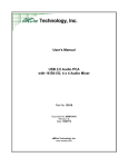
Screen Menus. The HFS 9000 implements controls as menus that are displayed
on the front-panel screen. Figure 1–1 shows the location of the MAIN MENU
button, which displays the top-level menu.
MAIN MENU Button
Figure 1–1: MAIN MENU Button Location
1–2
HFS 9000 User Manual
Getting Started
1. Press the MAIN MENU button.
Figure 1–2 shows the appearance of the Main menu. Each item in this menu
leads to a second-level menu. The menu you see may have a different menu
item highlighted, that is, black type on an amber background.
Figure 1–2: Main Menu Display
All menus have a name bar across the top and several rectangular menu
items beneath. Some menus have a prompt line between the name bar and
the menu items.
At all times, one and only one of the menu items is highlighted. The
SELECT button (Figure 1–3) will operate on this highlighted item. The
arrow keys surrounding the SELECT button let you change which item is
highlighted; each arrow button moves the highlighting to the next item in the
direction indicated.
SELECT and Arrow Buttons
Figure 1–3: The SELECT and Arrow Buttons
HFS 9000 User Manual
1–3
Getting Started
The Main menu gives you access to the twelve second-level menus:
H
The Pulse menu controls the pulse generator parameters such as pulse
timing and voltage levels.
H
The Time Base menu controls timing and triggering of the HFS 9000.
H
The Levels menu sets voltage levels and limits for the pulse generators.
H
The Signal menu controls channel display order, signal types, signal
names, and channel view.
H
The Vector menu controls vector parameters.
H
The Data Edit menu lets you edit the data streams produced by data time
generators.
H
The Data Fill menu lets you fill data time generator channel memory.
H
The Data Copy menu lets you copy blocks of data between data time
generator channels.
H
The Save/Recall menu lets you save and recall Stimulus System settings.
This menu also has the reset control.
H
The GPIB menu controls the GPIB parameters for remote programming.
H
The RS-232 menu controls the serial port parameters for remote
programming.
H
The Cal/Deskew menu provides calibration, self-test, instrument
identification, and pulse channel deskew functions.
The goal of this first part is to reset the HFS 9000. Since the reset control is
in the Save/Recall menu, you need to display this menu next.
2. Use the arrow buttons surrounding the SELECT button to move the menu
item highlight to the Save/Recall Menu item.
3. Press the SELECT button.
The Save/Recall menu, as shown in Figure 1–4, is displayed.
1–4
HFS 9000 User Manual
Getting Started
Figure 1–4: The Save/Recall Menu
Once in the Save/Recall menu, you can reset the HFS 9000 by selecting the
Reset menu item.
4. Use the arrow buttons to move the menu item highlight to the Reset menu
item.
5. Press the SELECT button.
Accidentally resetting the instrument can be inconvenient, especially if you
have spent some time getting the perfect setup. For your protection, the
HFS 9000 asks you to verify that you really want to reset.
To perform the verification, the HFS 9000 displays a temporary screen
dialog, as shown in Figure 1–5.
Figure 1–5: The Reset Verification Dialog
You can select from the options in the dialog by using either the up and
down Arrow keys, or by turning the knob. Once you have the proper
selection, press SELECT to perform the verified action.
6. Make certain that the Yes choice in the dialog is highlighted, and then press
the SELECT button to verify the reset request.
After the HFS 9000 resets, it displays the Main menu.
HFS 9000 User Manual
1–5
Getting Started
Part 2: Set the Time Base
The HFS 9000 provides several pulse or data time generation channels, but they
are all governed by a single time base. The next several steps set up the time
base to trigger itself repeatedly, and to have the time base specify a predetermined number of pulses from the pulse or data time generators.
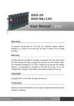
The controls for the time base are found in the Time Base menu, shown in
Figure 1–6.
1. Use the arrow buttons to highlight the Time Base menu, then press the
SELECT button to display the Time Base menu.
Figure 1–6: The Time Base Menu
The highlighted menu item is Mode, which you need to set for this example.
The time base normally waits for a trigger event, then specifies Count
number of pulses to be generated. After that, the time base pauses for a
re-arm time and then waits for the next trigger event. The display screen
above the Time Base menu graphically depicts this sequence. (see Figure 1–7).
Figure 1–7: Time Base Relationships
1–6
HFS 9000 User Manual
Getting Started
The Mode control has four possible settings:
H
Burst mode produces a burst of pulses whenever a trigger event is
detected.
H
Auto-Burst mode does not wait for a trigger before generating a burst of
pulses.
H
Auto mode generates a continuous stream of pulses without waiting for
a trigger or delaying for re-arm time.
H
Trig-Auto mode works like Auto mode except it does not begin until it
receives a trigger event.
To keep this example simple, we will use Auto Burst mode.
Set the mode control with the SELECT button. The prompt line, just below
the menu title, shows you the current mode setting with an arrow ( ). Each
time you press SELECT, the arrow moves to a different setting and the text
in the Mode item changes.
2. Press the SELECT button twice. When you are done, the prompt line should
appear as in Figure 1–8.
Figure 1–8: Mode Set to Auto-Burst
Two other items in the top line of the Time Base menu, Period and Count,
control the generated pulses. When either of these items is highlighted, the
waveform display above the menu is augmented to more clearly illustrate the
parameter being adjusted with that item.
H
Period controls the timing of the individual pulses produced by the pulse
generators. This can also be changed to be a Frequency control, as will be
demonstrated later in this tour.
H
Count determines the number of pulses generated after the startup delay.
Both of these items can be adjusted with the knob or each can be entered using
the keypad. When using the knob, the FINE button above the knob can give you
more control through finer resolution.
3. Use the arrow keys to highlight the Period item.
HFS 9000 User Manual
1–7
Getting Started
4. Use the knob to adjust the period to 6.25 ns. This will require that you use
the fine control.
First, use the knob to set the Period to 6.2 ns. Then, press the FINE button
to make the knob increments smaller. Note that the FINE light turns on.
Finally, use the knob to set it to 6.25 ns.
Numeric values can also be entered through the keypad. Type in the number,
and, if needed, press a key to specify the unit prefix (p, n, , m, k, M, or G).
Indicate that you are finished by pressing the ENTER key. You never need
to enter the units, such as seconds or Volts. If you make a mistake, the
BACKSPACE key will back up character by character.
5. Use the arrow keys to highlight the Count item.
6. Enter the value 5 by pressing 5 and ENTER.
As mentioned above, the Period item can be changed to specify Frequency
instead. Period and frequency are two ways of specifying the same parameter.
When you use the SELECT button to change modes of this item, the readout
shows you the setting in that mode.
7. Use the arrow keys to highlight the Period item. Observe that the period
setting is 6.25 ns.
8. Press the SELECT button. Observe that the item changes to Frequency and
that the frequency setting is 160 MHz, the reciprocal of 6.25 ns.
9. Use the knob or the keypad to set the frequency to 150 MHz. If you left the
Fine knob control on from Step 4, turn it off to set the frequency quickly.
You have now set up the HFS 9000 to enable the output of pulses. You will see
the results in the next part, but first check to make sure your Time Base menu
appears as shown in Figure 1–9.
Figure 1–9: The Time Base Menu After Adjustment
1–8
HFS 9000 User Manual
Getting Started
The other settings do not require adjustment for this tutorial example. Since the
HFS 9000 is in Auto-Burst mode, no input trigger is needed to generate pulses.
The UNDO Button. Whenever you change a setting, the HFS 9000 remembers the
old setting as well. Should you then change your mind, you can press the UNDO
button. The UNDO button is located to the right of the display panel. Pressing
the UNDO button twice cancels the undo.
10. Press the UNDO button. Note that the original frequency setting of 160 MHz
is restored.
11. Press the UNDO button again. Note that your changed value, 150 MHz, is
returned.
HFS 9000 User Manual
1–9
Getting Started
Part 3: Turn On Pulse
Output
The pulse and data time generators are all synchronized by the time base, but
currently none of the pulse or data time generator channels are switched on. You
can turn on any channel from the Pulse menu, but it is easiest to turn on a
channel from the front panel.
Depending on the configuration of your HFS 9000, you have from one to nine
pulse generator cards, with up to four channels each. The controls for each card
appear as in Figure 1–10.
SMA Connector
OUTPUT Button
TIME BASE
HFS 9PG2
HFS 9DG1
HFS 9DG2
Light
Figure 1–10: Pulse Generator, Data Time Generator, and Time Base Controls and
Connectors
1–10
HFS 9000 User Manual
Getting Started
1. Select any channel to use for output, and press the OUTPUT button for that
channel. Observe that the associated light turns on.
The HFS 9000 is now creating pulse trains. It puts out 5 pulses of 150 MHz
frequency. When that is done, it automatically starts over after the re-arm
time. If you have an oscilloscope, you can view the pulses that are being
generated.
2. Connect a cable from the associated OUTPUT connector to the signal input
connector of your oscilloscope.
3. Adjust your oscilloscope for a stable display of the pulses. If necessary, you
can also connect a cable from the Time Base card TRIGGER OUT
connector to the external trigger connector of your oscilloscope.
You may also observe the normal Burst mode operation of the HFS 9000.
4. Use the arrow keys on the HFS 9000 to highlight the Mode item of the Time
Base menu. Use the SELECT button to select Burst mode.
5. Observe that the oscilloscope is no longer triggered and displaying a signal.
6. Press the MANUAL TRIGGER button (to the right of the display panel).
Observe that each time you press this button, the oscilloscope shows one and
only one burst of output from the HFS 9000.
Part 4: Setting Up a Data
Time Generator
If a Data Time generator is installed in your HFS 9000, it can produce data
streams for device testing in addition to generating pulses. You can perform the
following steps only if your HFS 9000 has an HFS 9DG1 or HFS 9DG2 card
installed.
1. Perform all steps in “Reset the HFS 9000” of Getting Started, to reset all
HFS 9000 parameters to the factory defaults.
2. Use the arrow keys to highlight the Pulse menu, then press the SELECT
button to display the Pulse menu.
3. Using the Channel menu item, select a channel located on a data time
generator card.
For a channel to generate a data stream, the signal type of the channel must be
set appropriately. The available signal types are: NRZ-Non-Return to Zero; RZ,
Return-to-Zero; and R1, Return-to-One. A data time generator channel can also
be set to DC (direct current).
4. Highlight the Signal Type menu item in the Pulse menu. (Figure 1–11).
Turn the knob to change the signal type.
HFS 9000 User Manual
1–11
Getting Started
Figure 1–11: Setting the Signal Type
5. Observe how the illustration at the top of the display changes with the signal
type. Set the signal type to NRZ.
6. Press the MAIN MENU button.
7. Use the arrow keys to highlight the Data Fill menu and press the SELECT
button.
A channel is initially filled with zeros. You can change the data in the
channel using the Data Fill menu or by editing the data in the channel one bit
at a time in the Data Edit menu. The Data Fill menu is the quickest method
for placing data in a channel using the front panel.
The commands in the Data Fill menu work on a “Block” of vectors. A Block
is defined by a start vector and an end vector. Initially the block start and end
vectors are set to 0.
8. Highlight the Block End menu item. On the numeric keypad, press 1, 5, and
ENTER. This sets the block end vector to 15.
Blocks are filled using the Fill Block with Method menu item. The three
parameters for this menu item are Constant, Method, and Fill Scale. Constant
provides the value used to fill a block or the starting value for the Count Up,
Count Down and Random fill methods. Method specifies how a channel is
filled with data; the options are Constant, Invert, Count Up, Count Down, and
Random. Fill Scale is the number of vectors that are filled with a value before
generating a new fill value.
1–12
HFS 9000 User Manual
Getting Started
9. To set the fill method, use the arrow keys to highlight the Method menu
item.
10. Turn the knob to select each of the different fill methods. Observe the
descriptions that appear above the menu.
11. Select the Constant method.
12. Use the arrow keys to highlight the Fill Block with Method menu item.
Press the SELECT key.
13. A menu will appear informing you that the operation cannot be undone.
Press the SELECT key to allow the operation to proceed.
To view the results of the fill operation, you can view the channel data in the
Data Edit menu.
14. Press the MAIN MENU button. Highlight the Data Edit Menu item and
press SELECT.
When the Data Edit menu appears, you will see the selected channel and the
data that has filled it.
Figure 1–12: Viewing Channel Data
You can edit each of the bits in the channel from the front panel. Select a bit
by turning the knob and enter a new value from the numeric keypad.
HFS 9000 User Manual
1–13
Getting Started
15. Turn the knob to highlight vector 7.
16. Press 0 on the numeric keypad.
Observe that the 1 in vector address 7 is replaced by a 0 and the cursor
moves down to the next vector.
This completes your brief tour of the HFS 9000 Stimulus System. Refer to the
Operating Basics and Reference sections in this manual for more details on
operating your HFS 9000.
1–14
HFS 9000 User Manual
An Operator Overview
The Operating Basics section is arranged as an alphabetic list of topics. Each
topic covers one aspect of the operation of the HFS 9000. The topics that follow
this operator overview are:
Calibration
Channels
Data Time Generators
Deskew
GPIB
Levels
Phase Lock
Power On
Pulse Generators
Reset
RS-232-C
Saved Settings
Self Test
Time Base
Trigger
Timing and Pulses (Burst and Auto-Burst Modes)
Trigger Event
The Frequency or Period setting
determines the frequency or
duration of the pulse windows.
See page 2–62.
Trigger In
The Count setting determines the
number of pulse windows in a
burst — see page 2–62. Pulses
may occur at any time and be any
width within the pulse window.
Each channel may independently
set such pulse parameters as
width, phase, lead delay, and
trailing delay. See page 2–45.
Channel
Outputs
The Out Period setting determines
which pulse window the output
trigger is associated with; in this
case it is the third pulse window.
See page 2–62.
HFS 9000 User Manual
Startup Delay
(fixed at ~130 ns)
Time Zero
Reference
Pulse Windows
Trigger Out
2–1
An Operator Overview
The HFS 9003 Front Panel
NEXT CHANNEL and PREVIOUS
CHANNEL buttons let you select a
channel in menus that have channel
parameters. This convenience avoids a
lot of menu navigation. See page 2–11.
The Generator cards have connectors for normal
OUTPUT and inverted OUTPUT, along with
buttons to turn the outputs on and off and lights to
The UNDO button restores the
HFS 9000 to the state it was in before indicate whether those outputs are on. The
TRANSDUCER IN connector (PG cards only)
your last change. When you change
lets you apply a logic signal to directly drive a
menus, you can no longer undo the
channel. See pages 2–13 and 2–45.
previous operation.
REMOTE light and SRQ button —
used for operator interaction when the
HFS 9000 is controlled from a
computer or controller. See page 2–31.
RUN/STOP lets you start and stop the
time base as necessary. The RUNNING
light indicates whether or not the time
base is running.
Numeric keypad lets you type a
number for any selected menu
item having a numeric value. End
your number by pressing the
ENTER button. See page 1–8.
2–2
The MANUAL TRIGGER button
simulates a trigger event that normally
occurs as a signal at the TRIGGER IN
connector. See page 2–68.
The knob and FINE button let you adjust the
value of any selected menu item that has a
numeric value. The FINE button gives you finer
knob control. The FINE light tells you when the
knob is in fine granularity mode. See page 1–7.
SELECT, arrow, and MAIN MENU buttons
navigate through the menus. MAIN MENU
displays the main menu. The arrow buttons
change which menu item is selected — see
page 2–4. In the main menu, SELECT
displays the selected menu. In other menus,
SELECT may perform an action or change
the way an item works — see page 1–7.
The Time Base card has
connectors for timing input and
output, including the TRIGGER
IN, TRIGGER OUT connectors
(see page 2–65), the PHASE
LOCK IN and FRAME SYNC IN
connectors (see page 2–41), and
the SKEW CAL IN connector (see
page 2–7).
ON/STANDBY switch turns on the HFS 9000
or turns it off (standby). Even when on
standby, some circuits have line power
applied. To remove all power, disconnect the
power cord from the HFS 9000.
The CPU card has connectors for
the SERIAL PORT (see page
2–53) and for the GPIB bus (see
page 2–29).
HFS 9000 User Manual
An Operator Overview
The HFS 9009 Front Panel
SELECT, arrow, and MAIN MENU buttons
navigate through the menus. MAIN MENU
displays the main menu. The arrow buttons
change which menu item is selected — see
page 2–4. In the main menu, SELECT
displays the selected menu. In other menus,
SELECT may perform an action or change the
way an item works — see page 1–7.
ON/STANDBY switch turns on the
HFS 9000 or turns it off (standby).
Even when on standby, some circuits
have line power applied. To remove all
power, disconnect the power cord from
the HFS 9000.
The REMOTE light and SRQ button
are used for operator interaction when
the HFS 9000 is controlled from a
computer or controller. See page 2–31.
The knob and FINE button
let you adjust the value of
any selected menu item
that has a numeric value.
The FINE button gives you
finer knob control. The
FINE light tells you when
the knob is in fine
granularity mode. See
page 1–7.
The UNDO button restores the
HFS 9000 to the state it was in before
your last change. When you change
menus, you can no longer undo the
previous operation.
The MANUAL TRIGGER button
simulates a trigger event that
normally occurs as a signal at the
TRIGGER IN connector. See
page 2–68.
RUN/STOP lets you start and stop
the time base as necessary. The
RUNNING light indicates whether
the time base is running or not.
Numeric keypad lets you
type a number for any
selected menu item having
a numeric value. End your
number by pressing the
ENTER button. See
page 1–8.
The Time Base card has connectors for
The Pulse Generator cards have connectors
timing input and output, including the
for normal OUTPUT and inverted OUTPUT,
TRIGGER IN and TRIGGER OUT
along with buttons to turn the outputs on and
connectors (see page 2–65), the PHASE
off and lights to indicate whether those outputs
LOCK IN and FRAME SYNC IN connectors
are on. The TRANSDUCER IN connector lets
(see page 2–41), and the SKEW CAL IN
you apply a logic signal to directly drive a
connector (see page 2–7).
channel. See pages 2–13 and 2–45.
NEXT CHANNEL and PREVIOUS
The CPU card has connectors for the
CHANNEL buttons let you select a
SERIAL PORT (see page 2–53) and for
channel in menus that have channel
the GPIB bus (see page 2–29).
parameters. This convenience avoids a
lot of menu navigation. See page 2–11.
HFS 9000 User Manual
2–3
An Operator Overview
Menu Navigation
1. Press the MAIN MENU button to display the top-level menu.
2. Use the arrow buttons to move to the menu you want to display.
3. Press the SELECT button to display that menu.
2–4
HFS 9000 User Manual
An Operator Overview
Menu Map
HFS 9000 User Manual
2–5
An Operator Overview
Menu Map (Cont.)
2–6
HFS 9000 User Manual
Calibration
The HFS 9000 is shipped in a calibrated state, with the outputs deskewed to the
front panel. Calibration settings are saved in a special non-volatile memory
which is separate from any other memory in the instrument. Calibration adjusts
the instrument to its internal voltage and timing references.
Calibrating the HFS 9000
It is important to calibrate the HFS 9000 after the instrument has been repaired
or after the instrument has been reconfigured by adding or changing cards. It is
also necessary to calibrate the HFS 9000 if you operate the instrument in an
environment where the ambient temperature differs by more than 5_ C from the
temperature of the last calibration. As a matter of routine, you should calibrate
the HFS 9000 every six months.
To calibrate the HFS 9000, use the Calibrate item in the Cal/Deskew menu.
Figure 2–1 shows this menu.
Figure 2–1: The Cal/Deskew Menu
Run the calibration procedure only when the HFS 9000 has been powered on for
20 minutes in the temperature environment you expect it to be used. You will
need a 20 inch SMA cable; the cable supplied as a standard accessory is
acceptable. The calibration process will take approximately one minute for every
channel installed in the HFS 9000.
When you select the Calibrate item in the Cal/Deskew menu, a dialog box asks
you for verification. If you proceed, the HFS 9000 will prompt you to attach the
SMA cable from the front panel SKEW CAL IN connector first to the TRIGGER OUT connector, and then to each channel OUTPUT connector in turn.
During the time that the channels are connected, calibration is performed
automatically.
HFS 9000 User Manual
2–7
Calibration
Diagnostic Failure of Calibration Memory
Whenever you power on the HFS 9000, diagnostics check the integrity of the
calibration memory. If the test fails, the instrument may require service. When
this happens, nominal values are put into calibration memory, and the instrument
will be uncalibrated. However, the HFS 9000 will let you continue to operate the
instrument after the initial warning that calibration memory has been reset.
Check out the instrument to be certain it is running correctly and run the
calibration procedure before operating the instrument.
If the instrument configuration has been changed since last power on (for
example, boards have been changed or firmware memory has been updated), the
power-on diagnostics will detect this as a failure of calibration memory integrity.
Run the calibration procedure before operating the instrument.
NOTE. Some features will not function if the HFS 9000 is in an uncalibrated
state.
2–8
HFS 9000 User Manual
Channels
You have from 2 to 36 channels of output, depending on the type and number of
cards you have installed in your HFS 9000 system. The HFS 9PG1 and
HFS 9PG2 pulse generator cards provide two output channels, while the
HFS 9DG1 and HFS 9DG2 data time generator cards provide four output
channels.
Channel Names
Each pulse generator card is assigned the letter designation A, B, C, D, E, F, G,
H, or I depending on its physical position in the Stimulus System mainframe.
The channels on HFS 9PG1 and HFS 9PG2 cards are numbered 1 and 2. The
channels on HFS 9DG1 and HFS 9DG2 cards are numbered 1, 2, 3, and 4. The
full designation for a channel is a letter and a number; for example A1, C2, H4,
etc. Figure 2–2 shows the locations of the channels in a typical instrument.
Channel C2 Channel C4
Channel C1 Channel C3
Channel B1 Channel A1
Channel B2
Channel A2
Channel B4
Channel B3
Figure 2–2: Channel Locations
HFS 9000 User Manual
2–9
Channels
Channel Controls
HFS 9PG2
On HFS 9PG1, HFS 9PG2, and HFS 9DG1 cards, each channel has both normal
OUTPUT and inverted OUTPUT connectors. The HFS 9DG2 card has only one
connector per channel, OUTPUT. Each output connector of each channel has a
button to turn on or off that output, and a light telling whether or not that output
is on. In addition, each channel on HFS 9PG1 and HFS 9PG2 cards have a
TRANSDUCER IN connector. (For more information on the Transducer mode,
see page 2–49.) Figures 2–3, 2–4, and 2–5 show the layout of controls for the
different pulse and data time generator cards.
HFS 9DG1
Figure 2–3: Channel Controls on an HFS 9PG2 Card
HFS 9DG2
Figure 2–4: Channel Controls on an HFS 9DG1 Card
Figure 2–5: Channel Controls on an HFS 9DG2 Card
You can also turn off normal and inverted output for any channel with the Pulse
menu items Output and ~Output. When an output is off, the channel is
internally tri-state. Off does not drive an output to ground.
2–10
HFS 9000 User Manual
Channels
Selecting Channels
Several menus provide controls that apply to individual channels. In these
menus, the upper left menu item lets you set which channel the other menu items
control. You use the SELECT button or the knob to select the desired channel.
Once you have set the desired channel, you can use the other menu items to
control the parameters for that channel.
An alternate method of selecting channels is to use the NEXT CHANNEL and
PREVIOUS CHANNEL buttons at the left of the display.
The Pulse menu, the Levels menu, and the Signal menu have associated channel
displays above the menu. In these displays, each channel is labeled with its
channel name (A1, C2, etc.). The name of the channel that is selected to be
controlled by the other menu items is highlighted, that is, displayed in black
lettering on an amber background. Figures 2–6, 2–7, and 2–8 show these three
menus and indicate the highlighting on the associated displays.
Selected
Channel
Figure 2–6: Pulse Menu, Showing Channel Selection
HFS 9000 User Manual
2–11
Channels
Selected
Channel
Figure 2–7: Levels Menu, Showing Channel Selection
Selected
Channel
Figure 2–8: Signal Menu, Showing Channel Selection
2–12
HFS 9000 User Manual
Data Time Generators
The HFS 9DG1 and HFS 9DG2 Data Time Generators combine the capabilities
of a data time generator, pulse generator, and switch matrix in a single instrument. As part of the HFS 9000 Stimulus System, the data time generator can
deliver complete data and timing signals to the circuit under test. Within the data
time generator, every output is capable of producing any type of data and
formatting — not just data and pulses. Complete control over rise and fall times,
widths, and voltage levels on all data is provided. Because of their unique digital
architecture, the data time generators can place an edge anywhere, even delaying
waveforms across cycle boundaries.
Controls for the data time generators are accessed in several menus. Controls that
affect the pulse parameters of the data time generators are in the Pulse menu, as
shown in Figure 2–9. For more information on pulse parameter controls, see
page 2–45.
Figure 2–9: The Pulse Menu
Menus that control data generation parameters are the Signal menu, the Data Fill
menu, the Data Copy menu, and the Data Edit menu.
HFS 9000 User Manual
2–13
Data Time Generators
Turning Channels On and Off
The HFS 9DG1 provides two output connectors for each channel. Channels are
identified by number; they are labeled CH 1 through CH 4. Each channel
provides both normal and logically inverted output and are labeled OUTPUT
and OUTPUT. The HFS 9DG2 provides one output connector for each channel,
labeled CH 1 through CH 4.
Each output connector has a button to turn that output on or off, and a light
showing whether or not that output is on. You can also turn on or off the normal
or inverted output of any channel using the Pulse menu items Output and
~Output.
Naming a Channel
Generally, a channel is referred to by its slot and channel number; for example,
you would refer to channel 1 of the card in slot A as channel A1. Additionally,
you can identify a channel with a name. This would enable you to identify the
signal going to the Write Enable pin of the DUT (device under test) as “WE”
rather than A1. Any channel on any card can be given a name; this feature is not
limited to the data time generator cards.
Assigning a name to a channel is performed by the Signal Name item in the
Signal menu (see Figure 2–10).
Figure 2–10: The Signal Menu
To assign a name to a channel, select the channel using the Channel menu item.
Select the Signal Name menu item and press SELECT. The dialog box appears
as in Figure 2–11.
2–14
HFS 9000 User Manual
Data Time Generators
Figure 2–11: The Signal Name Dialog Box
To enter a name, choose a character by turning the knob or pressing the arrow
keys. When the character is highlighted, press SELECT to signify your selection
and enable selection of the next character. A signal name can be up to six
characters long. When you are finished selecting characters, press ENTER. The
dialog box will disappear and the new signal name will appear in the Signal
Name and Channel menu items (see Figure 2–12).
Figure 2–12: Signal Menu After Entering Signal Name
HFS 9000 User Manual
2–15
Data Time Generators
You can also name buses. To do this, assign the same name to two or more
channels, but use different numbers as the last character in the name. You could
create an bus named “ADDRx”, where x represents the number of each line of
the bus (see Figure 2–13).
Figure 2–13: Naming a Bus
If you create a bus, you can choose to view the bus by individual channel or as a
single entity that represents the whole group. You change the view of channels
with the View item. You can choose to view channels as a Channel or as a
Group. In this manual, we will use “Signal” to refer to a channel that has been
named. Figure 2–14 below is the same display as above except that the View is
set to Group.
Figure 2–14: Viewing a Bus by Group
Signal Type
A Signal on an HFS 9DG1 or HFS 9DG2 can be of five different types: Pulse,
NRZ (Non-Return to Zero), RZ (Return to Zero), R1 (Return to One), and DC.
The signal type is assigned with the Signal Type menu item (see Figure 2–15).
2–16
HFS 9000 User Manual
Data Time Generators
Figure 2–15: Assigning Signal Type
To set the signal type, select the channel using the Channel menu item. Select the
Signal Type menu item. Turn the knob to select the correct signal type (the
Transducer signal type appears in the menu but it cannot be assigned to data
time generator channels).
Changing Display Order
You can change the order in which signals are displayed using the Move
Up/Down and Reset Order menu items in the Signal menu. To change the
display order of signals, select the channel you want to move with the Channel
menu item. After selecting the channel you want to move, select the Move Up/
Down menu item (see Figure 2–16). To move the channel to a different position
in the display order, turn the knob.
Figure 2–16: Changing the Display Order
If you wish to return the display order to the default order (A1, A2, A3, A4, B1,
B2, etc.), select the Reset Order menu item and press SELECT. A dialog box
HFS 9000 User Manual
2–17
Data Time Generators
will appear asking you to confirm that you wish to reset the channel order. The
default answer is Yes. To select Cancel, use either the knob or the up/down
arrow keys to change the selection. When the correct response is highlighted,
press SELECT.
Entering Vector Data
Data can be entered in three ways. One way is to enter data one bit at a time
using the Data Edit menu. Another way is to use the Data Fill and Data Copy
menus. The third method is used if you have generated test vectors with a CAD
system or Tektronix BitWriter Software. With this method, you transfer your
vector data into the HFS 9000 via the programming interface. For more
information on entering data via the programming interface, please refer to
page 3–121.
Editing Vectors
You view and edit the contents of vectors from the Data Edit menu. There are no
menu items in the Data Edit menu. To display the Data Edit menu, select Data
Edit Menu from the main menu (see Figure 2–17).
Signals
Start Vector Indicator
Cursor
This line indicates the direction the cursor
will move when the knob is turned.
Vectors
These represent the data stream for
each Signal. Each number can
represent one, two, or four bits of data
depending on the Data Radix.
Loop Vector Indicator
End Vector Indicator
Figure 2–17: The Data Edit Menu
2–18
HFS 9000 User Manual
Data Time Generators
To edit the contents of a vector, move the cursor using the knob or the arrow
keys. When the appropriate datum is highlighted, type the change using the
keypad. When you type the change, the highlighted datum is changed and the
cursor moves to the next datum. Note that the number of bits each datum
represents depends on the Data Radix setting.
Vector Parameters
There are several parameters related to vectors; these parameters are accessed
from the Vector menu. From the Vector menu, you can set the Start, Loop, and
End addresses. The vector radix, data radix, and time base mode are also set in
this menu (see Figure 2–18).
Figure 2–18: The Vector Menu
To set vector parameters, select the channel whose parameters you wish to set
using the Channel menu item. Next, select the parameter you wish to set and use
the knob (or numeric keypad as appropriate) to change the value.
H
Start sets the vector of the first data bit output.
H
Loop sets the start vector of all cycles except the first. The Loop value is
used only in Auto and Trig Auto modes; it is ignored in Burst and Auto
Burst modes. Loop is useful if you need to send setup information with the
first cycle of data, but don’t want it to be sent out on subsequent cycles. Of
course, Loop can be set to the same vector as Start.
There are some constraints on Loop size (defined as: End – Loop + 1). If
vector consumption (defined as: End – Start +1) is:
HFS 9000 User Manual
2–19
Data Time Generators
≤8192, there are no constraints on Loop size
> 8192, then Loop size must be divisible by 2
>16384, then Loop size must be divisible by 4
>32768, then Loop size must be divisible by 8
H
End sets the vector of the last data bit output.
NOTE. Start, Loop, End, Mode, and Vec Radix are global values. If you change
these settings for any channel, the change applies to all channels.
H
The Mode menu item determines how data is output from the data time
generator. It is the same as the Mode menu item in the Time Base Menu.
In Burst mode, the HFS 9000 waits for a trigger event at the TRIGGER IN
connector, a remote *TRG command, or a press of the MANUAL TRIGGER button. When a trigger event is detected, the HFS 9000 waits for
approximately 130 ns (the startup delay) before outputting data. Data output
begins with the Start vector and stops with the End vector. The HFS 9000
then awaits the next trigger event.
In Auto-Burst mode, output is similar to Burst, except that the HFS 9000
creates it own trigger events. There is a delay of approximately 15 s
between bursts.
H
In Auto mode, data is output continuously without waiting for trigger events
and without any startup events. Data output begins with the Start vector.
Once End is reached, the output begins again at Start (or Loop if it is
different from Start) and continues until stopped by a knob turn or ASCII
interface command (RS-232-C or GPIB).
In Trig-Auto, the output is the same as with Auto mode, but output does not
begin until a trigger event is received. The HFS 9000 waits for a trigger
event at the TRIGGER IN connector, a remote *TRG command, or a press
of the MANUAL TRIGGER button.
If data output is stopped when Mode is set to Auto or Trig Auto, note that all
channels may not stop on the same vector. Additionally, if a signal is set to
NRZ and filled with “1”s as data, the channel may stop in a “0” state.
Filling Vectors with Data
2–20
H
Vec Radix specifies how vectors are displayed.
H
Data Radix specifies how data is displayed in the Vector Edit menu. Data
Radix applies only to the selected channel.
To quickly fill vectors with data, use the Data Fill menu (see Figure 2–19). The
underlying concept used in the Data Fill menu is the idea of a Block. A Block is
HFS 9000 User Manual
Data Time Generators
a group of vectors. You specify a Block using a starting vector and either an
ending vector or a block size. Once a Block is appropriately specified, you either
fill the block with data or clear the block of data.
A Block is filled using the Fill Block with Method menu item. The three
parameters for Fill Block with Method are Constant, Method, and Fill Scale.
Figure 2–19: The Data Fill Menu
H
Channel selects the Signal (named channel) or bus on which the Fill Block
with Method and Clear Block commands operate.
H
Block Start sets the vector where fill or clear operations begin. Turn the
knob or use the numeric keypad to change the Block Start vector.
H
Block End sets the last vector in the Block. Turn the knob or use the
numeric keypad to change the Block End vector. Pressing SELECT while
Block End is highlighted changes the menu item to Block Size.
Block Size provides a second method of defining a block. Block Size sets
the size of the block, regardless of the Block Start vector.
HFS 9000 User Manual
H
Clear Block sets all the bits in the Block to zero. Note that if View is set to
channel, only the selected channel is cleared. If View is set to Group, all
channels in the specified bus are cleared.
H
Constant is a number used by the Method menu item. Depending on the fill
method selected, the constant is the number used to fill a Block or a
2–21
Data Time Generators
parameter used when filling a block. Note that valid numbers for Constant
depend on the Data Radix setting. To change the constant, turn the knob or
use the numeric keypad.
H
Method specifies the algorithm used to fill a Block with data.
Constant fills the Block with the value in the Constant menu item.
Invert logically inverts the value of all the data in the Block.
Count Up fills each vector in the Block with an incrementally larger value.
Count Up starts with the value specified by the Constant menu item.
Count Down fills each vector in the Block with an incrementally smaller
value. Count Down starts with the value specified by the Constant menu
item.
Random fills vectors in the Block with a pseudo-random data pattern. The
pattern generated is based on the value of Constant.
H
Fill Scale is a multiplier. It sets the number of vectors that receive each fill
pattern. For example, if the fill method is set to Count Up and Constant is set
to 0, then the Start vector is filled with a 0, the next vector receives a 1, the
next vector receives a 2, etc. If Fill Scale is set to 3, then the Start vector and
the next two vectors receive 0s, the next three vectors receive 1s, etc.
Figures 2–20 and 2–21 show the result of setting Fill Scale to 1 and to 3.
Fill Scale was set to 1 when this block was filled.
Thus, every vector receives a different value.
Figure 2–20: A Block Filled with Fill Scale Set to 1
2–22
HFS 9000 User Manual
Data Time Generators
Fill Scale was set to 3 when this block was filled.
Thus, each group of 3 vectors receives the same value.
Figure 2–21: A Block Filled with Fill Scale Set to 3
H
Copying Vector Data
Selecting Fill Block with Method fills the Block using the parameters set in
Constant, Method, and Fill Scale.
You can also copy data in one Block to another using the Data Copy Menu (see
Figure 2–22). The Data Copy menu provides the capability to copy a block of
data from one channel to another or to duplicate a block of data within the same
channel. You can also swap blocks of data between channels or within the same
channel.
Aside from copying blocks of data, the Data Copy Menu can be used to insert a
new vector into a Block. To insert a new vector into a Block, just copy the Block
to a Dest Start vector one higher than the new vector. For example, if you need to
insert a new vector at 000010, copy the vectors from 000010 through the end of
the Block to a Dest Start address of 000011 (1 higher than 000010). Then edit
the new vector in the Data Edit menu. You can delete single vectors using the
same method — set the Dest Start vector to one less than the vector to be
removed.
HFS 9000 User Manual
2–23
Data Time Generators
Figure 2–22: The Data Copy Menu
H
Channel selects the Signal (named channel) or bus on which the Copy
Block to Dest and Swap Block with Dest commands operate.
H
Block Start sets the vector where copy or swap operations begin. Turn the
knob or use the numeric keypad to change the Block Start vector.
H
Block End sets the last vector in the Block. Turn the knob or use the
numeric keypad to change the Block End vector. Pressing SELECT while
Block End is highlighted changes the menu item to Block Size.
Block Size provides a second method of defining a block. Block Size sets
the size of the block, regardless of the Block Start vector.
2–24
H
Copies sets the number of times the Block is copied.
H
Dest Chan specifies the channel that will receive the copied Block.
H
Dest Start sets the vector where the copied Block will begin.
H
Swap Block with Dest swaps the Block defined by Block Start and Block
End/Size with the Block that begins at Dest Start.
H
Copy Block to Dest copies the Block defined by Block Start and Block
End/Size to the Block that begins at Dest Start.
H
Vec Radix specifies how vectors are displayed in the Vector Edit menu.
H
View sets the display mode to either Channel or Group.
HFS 9000 User Manual
Deskew
You can adjust two parameters to deskew the HFS 9000 so that its timing
matches the external circuitry you are working with. Both these parameters,
Pretrigger and Chan Delay, are in the Cal/Deskew menu as shown in Figure 2–23.
NOTE. Channel delay is set for each channel individually, while Pretrigger
affects all channels by changing the delay relative to the HFS 9000 output
trigger.
Figure 2–23: The Cal/Deskew Menu
Channel Delay
You can set Chan Delay (channel delay) independently for each channel
(Figure 2–24 shows the result of deskewing one channel). Channel delay adjusts
the time between the trigger out the detection of a trigger event at the TRIGGER IN connector and the beginning of the first pulse window of the burst.
There is normally a delay of approximately 130 ns between these two events.
Channel delay lets you adjust the delay for each channel from –60 ns to 2 s.
This value is added to the 100 ns internal delay.
In the Cal/Deskew menu, the Channel menu item lets you set which channel the
Chan Delay menu item controls. Use the SELECT button or the knob to select
the channel. Once you have set the desired channel, you can set the channel
delay for that channel. An alternate method of channel selection is to use the
NEXT CHANNEL and PREVIOUS CHANNEL buttons next to the display.
HFS 9000 User Manual
2–25
Deskew
Before Deskew
Long Cable
Short Cable
After Deskew
Long Cable
Short Cable
Chan Delay added to
channel with short cable, to
synchronize pulse outputs.
Figure 2–24: Deskewing Channels
Follow this sequence to deskew several channels so that they deliver pulses
simultaneously to your device under test:
1. Connect the generator channels to the device under test using the exact
cabling that you will use in the actual testing.
2. Set the Chan Delay of each channel to zero.
3. Turn on pulse output for each channel you are using. On each channel, set
the Lead Delay to zero or the Phase to 0%. Set the Count to 1.
4. Using an oscilloscope, measure the time between the trigger event on the
trigger signal and the rising edge of the pulse of each channel. Note which
channel has the longest time delay; this is the reference channel.
5. For each channel in turn, adjust the Chan Delay until the time between the
trigger event and the rising edge of the channel pulse matches that of the
reference channel.
You can do this arithmetically, by computing the time difference and setting
Chan Delay to that value. Alternately, you can do this using the oscilloscope, by probing each channel with the same oscilloscope probe and
adjusting the Chan Delay until the pulse timing matches the reference
channel.
2–26
HFS 9000 User Manual
Deskew
This procedure synchronizes the channels so that they all deliver pulses to the
device under test simultaneously. The procedure compensates for timing
differences in the electrical paths of the channels, for example those caused by
unequal cable lengths.
Once you have deskewed the channels, you can introduce controlled timing
variations by using the Lead Delay or Phase menu items.
Trigger Out Pretrigger
The output trigger can be adjusted to occur before the beginning of the specified
pulse window. The default setting of 70 ns means that the trigger out signal
appears 70 ns before the beginning of the pulse window.
Pretrigger can be used to compensate for the delay times incurred by cabling
between the TRIGGER OUT connector and the device to be triggered.
Pretrigger is also useful to compensate for an oscilloscope insertion delay; for
example, the typical insertion delay for the Tektronix CSA 803 is approximately
35 ns.
HFS 9000 User Manual
2–27
Deskew
2–28
HFS 9000 User Manual
GPIB
You can use the GPIB (IEEE 488.2-1987) interface to control the HFS 9000
from a remote controller or computer. The Reference section of this manual,
gives you step-by-step details of how to set up the HFS 9000 for remote
operation. The following information describes the settings and controls that
affect GPIB operation.
Connect your HFS 9000 to the GPIB using an IEEE STD 488 GPIB cable
(available as Tektronix part number 012-0991-00). Figure 2–25 shows the
location of the GPIB connector on the front of the HFS 9000.
HFS 9000 User Manual
2–29
GPIB
GPIB Connector
GPIB Connector
Figure 2–25: GPIB Connector Location
2–30
HFS 9000 User Manual
GPIB
Operator Controls
One common application for the HFS 9000 is as one instrument in a suite of
automated test equipment. In this environment, the controlling program may
need to operate the HFS 9000 for extended periods without operator intervention. The program may need to stop to have the operator perform some specific
action. The program then needs to have some indication from the operator that
the operator action has been completed and the program can continue the suite of
tests.
The HFS 9000 supports this environment in two ways:
HFS 9000 User Manual
H
The front-panel interface of the HFS 9000 can be locked out (disabled) and
unlocked using commands sent from a remote controller or computer. When
the front panel is locked out, the REMOTE light at the left of the display is
lit. However, the SRQ button and the channel buttons on the pulse generator
cards cannot be locked out. These buttons are always operational regardless
of the state of lockout.
H
The operator can send a trigger to the controlling program by pressing the
SRQ button, just below the REMOTE light (see Figure 2–26).
2–31
GPIB
REMOTE Light
SRQ Button
SRQ Button
REMOTE
Light
Figure 2–26: SRQ Button and REMOTE Light Locations
When the program expects the operator to perform some action before it can
continue, it unlocks the front panel interface and displays a message to prompt
the operator. The operator then performs the necessary action, after which he or
she presses the SRQ button. The program recognizes the button press, locks out
the front panel, and continues to the next automated test.
2–32
HFS 9000 User Manual
GPIB
The GPIB Menu
Figure 2–27: The GPIB Menu
NOTE. The settings of the GPIB parameters are not changed when you reset or
factory reset the HFS 9000 or when you recall settings.
HFS 9000 User Manual
H
Address lets you set the device address of the HFS 9000 (see Figure 2–27).Valid device addresses are 0 through 30. Once the device address
is set, all other devices will communicate with the HFS 9000 using its device
address. Every device on a GPIB bus must have a unique device address.
H
On Bus lets you “turn off” or “turn on” the GPIB interface. When set to Off,
the HFS 9000 GPIB interface is disabled and the remaining devices on the
bus operate as if the HFS 9000 were not connected to the bus.
H
Debug specifies whether commands and control settings appear in the
HFS 9000 display. When debug is on, a display window appears showing the
most recent commands sent to the HFS 9000, and the status of several
control settings. Appendix C, Interface Specifications, gives complete
information about using debug mode.
2–33
GPIB
2–34
HFS 9000 User Manual
Levels
You can set the voltage levels that the HFS 9000 uses for logical high and logical
low. You can also limit the voltage levels that can be set with the normal level
controls. Voltage level and level limit controls are provided for each channel
individually. The output voltage range varies between cards as shown in
TableĂ2–1.
Table 2–1: Output Voltage Limits
Pulse/Data Time Generator
Minimum Low Level
Maximum High Level
HFS 9PG1
–2 V
+2.6 V
HFS 9PG2
–2 V
+5.5 V
HFS 9DG1
–2.5 V
+5.0 V
HFS 9DG2
–2.0 V
+5.5 V
When you turn level limit on, the voltage level settings for each channel are
adjusted, if necessary, to be within the limit boundaries set for that channel.
NOTE. Turning limiting off does not restore the channel voltage levels to their
previous, unlimited values.
Setting Voltage Levels
The controls for levels are located in the Pulse Menu (see Figure 2–28) or the
Levels Menu (see Figure 2–29).
HFS 9000 User Manual
2–35
Levels
Figure 2–28: The Pulse Menu
The Pulse menu has these level controls:
H
Channel lets you set the channel that the other menu items control. Use the
SELECT button, the knob, or the PREVIOUS CHANNEL and NEXT
CHANNEL buttons to select channels.
H
High Level and Low Level are the voltage levels used for logical high and
low. These can be set by knob or entered by keypad. If limiting is on, you
will not be able to extend the voltages beyond the limits.
You can use the SELECT button to change High Level and Low Level into
Amplitude and Offset. Amplitude is the voltage difference between the
levels. Offset is the voltage level assigned to the midpoint between the
levels.
Setting Level Limits
The controls for level limits are located in the Levels Menu (see Figure 2–29).
Controls for voltage levels are also provided here. The associated display
graphically shows the levels and limits for each channel.
2–36
HFS 9000 User Manual
Levels
Limit
Brackets
Voltage Bar
Figure 2–29: The Levels Menu and Associated Display
The Levels menu has these controls:
H
Channel lets you set the channel that the other menu items control. Use the
SELECT button, the knob, or the PREVIOUS CHANNEL and NEXT
CHANNEL buttons to select channels.
The currently selected channel is indicated in the associated level display by
having a denser level bar and having a highlighted channel name. The
currently selected channel is also shown in the Channel menu item.
H
High Level and Low Level are the voltage levels used for logical high and
low. These are the same controls provided in the Pulse menu. They can be
set by knob or entered by keypad. As you change these values, the voltage
bar in the associated display changes to match. If limiting is on, you will not
be able to extend the voltage bar beyond the limit brackets.
You can use the SELECT button to change High Level and Low Level into
Amplitude and Offset. Amplitude is the voltage difference between the
levels. Offset is the voltage level assigned to the midpoint of the amplitude
range.
H
HFS 9000 User Manual
High Limit and Low Limit are the voltage limits to use when limiting is on.
These can be set by knob or entered by keypad. As you change these values,
the limit brackets in the associated display change to match. If limiting is on,
moving a bracket into the voltage bar will cause the bar to shrink.
2–37
Levels
H
Limit sets limiting on or off. When limiting is on, any voltage levels that are
outside the limits are reset to their respective limits. Limiting also adjusts
voltage levels values as you change the limits.
Turning limiting off does not restore the channel voltage levels to their
previous, unlimited, values.
2–38
HFS 9000 User Manual
Phase Lock
You can synchronize and lock the HFS 9000 to an external timing source
connected to the PHASE LOCK IN connector. This timing source then replaces
the HFS 9000 internal clock. You can run the HFS 9000 at frequencies that are
power-of-two harmonics or sub-harmonics of the phase lock signal. For example,
you could run the HFS 9000 at 1/16th the phase lock frequency or at 32 times the
phase lock frequency.
When in phase lock mode, you can use an external signal connected to the
FRAME SYNC IN connector to provide a phase-locked trigger.
Establishing Phase Lock
The signal connected to PHASE LOCK IN must be stable and continuous. It
must not change frequency once phase lock is established. The frequency range
of the phase lock signal must be between 6 MHz and 630 MHz.
The PHASE LOCK IN signal must have a voltage between 0.8 V and 1.0 V
peak to peak. The input circuitry removes the DC component by passing the
signal through a 0.1 mF blocking capacitor. The signal is then terminated by a
50 W resistor to ground.
To ensure the proper operation of phase lock, it is important to calibrate the
HFS 9000 after the instrument has been repaired or after the instrument has been
reconfigured by adding or changing cards. It is also necessary to calibrate the
HFS 9000 if you operate the instrument in an environment where the ambient
temperature differs by more than 5_ C from the temperature of the last calibration. As a matter of routine, you should calibrate the HFS 9000 every six
months. Refer to page 2–7 for details about calibrating the HFS 9000.
Use the following procedure to establish phase lock and to put the HFS 9000 in
phase lock mode:
1. Connect the phase lock signal to the PHASE LOCK IN connector on the
Time Base Card (see Figure 2–30).
HFS 9000 User Manual
2–39
TIME BASE
Phase Lock
Figure 2–30: The Time Base Card Connectors
2. Use the PhaseLockIn item in the Time Base menu to set phase lock to On.
Figure 2–31 shows the Time Base menu with the detected phase lock
frequency above the menu.
NOTE. If the HFS 9000 cannot determine the phase lock frequency, an error
message is displayed. This will happen if the phase lock signal is not stable and
continuous, or if the phase lock signal is outside the allowed frequency range, or
if the HFS 9000 needs calibrating.
Figure 2–31: The Time Base Menu with the PhaseLockIn Menu Item
NOTE. If you need to change the frequency of the phase lock signal after phase
lock mode is established, turn phase lock mode off, then establish the new stable
frequency before turning on phase lock mode again.
Setting Period or Frequency During Phase Lock
When phase lock is first established, the setting of the Period or Frequency
menu items changes to reflect the period or frequency of the phase lock signal.
2–40
HFS 9000 User Manual
Phase Lock
You can change the frequency or period while in phase lock, but only by powers
of two; that is, you can repeatedly double or halve the period or frequency. If you
adjust period or frequency with the knob, each knob click will double or halve
the value in the menu item. The frequencies you can use are limited to those
within the frequency specifications of the HFS 9000.
Triggering During Phase Lock Mode
You can provide a triggering window while in phase lock mode. This triggering
window is the time during which the input at the FRAME SYNC IN connector
is held high. A trigger event is the first positive-going edge of the phase lock
signal that occurs during the triggering window (see Figure 2–32).
The FRAME SYNC IN is terminated through 50 W to –2.0 V. Logical low is
from –1.810 V to –1.475 V; logical high is from –1.165 V to –0.810 V. These are
standard ECL specifications.
Just as normal triggering (a trigger event at the TRIGGER IN connector) is only
operational during Burst mode operation, phase lock triggering using the
FRAME SYNC IN connector can only be used during Burst mode. (See
page 2–61 for a description of Burst, Auto-Burst, Auto, and Trig-Auto modes.)
Phase lock triggering is disabled when the Trigger In item in the Time Base
menu is Off.
Trigger Event
Phase Lock In
Frame Sync In
Pulse Output
Pulse Windows
130 ns Startup Delay
Figure 2–32: Phase Lock In and Frame Sync In Timing Relationships
HFS 9000 User Manual
2–41
Phase Lock
Phase Lock After Power on or Recall
Phase lock is set to off whenever you power on the HFS 9000 or whenever you
recall a setting. This is because a signal must be applied to the PHASE LOCK
IN connector before phase lock is established. Once you have recalled a setting
or powered on, you can connect your phase lock signal and then turn on phase
lock mode.
2–42
HFS 9000 User Manual
Power On
When you power on the HFS 9000, it runs the self test diagnostics. Then it
restores the instrument setting to the same way it was the last time it was
powered off with the exception of the following two conditions:
H
All outputs remained turned off. This prevents the HFS 9000 from damaging
any equipment or devices under test that happen to be connected during
power on.
H
The phase lock mode is turned off because phase lock requires an external
signal to be attached at the time phase lock is turned on. If you need to
restore phase lock mode, power the HFS 9000 on, connect the phase lock
signal to the PHASE LOCK IN connector then turn on phase lock using the
Time Base menu PhaseLockIn item.
Configuration
The HFS 9000 can display the configuration of the instrument. Use the View
Config item in the Cal/Deskew menu. Figure 2–33 shows this menu, and
Figure 2–34 shows a typical configuration display.
Figure 2–33: The Cal/Deskew Menu
Figure 2–34: A Typical Configuration Display
HFS 9000 User Manual
2–43
Power On
The configuration display shows the firmware version installed in the HFS 9000,
and the cards that are installed. Each card also shows the card ID in quotes. You
can change the card ID of any card through a programming interface by using the
command.
2–44
HFS 9000 User Manual
Pulse Generators
Pulse generators are the circuitry that generates the pulse signals specified by the
time base. The HFS 9PG1 and HFS 9PG2 pulse generator cards each have two
pulse generator channels. The HFS 9DG1 and HFS 9DG2 data time generator
cards, in addition to their capabilities as data generators, have similar pulse
generator capabilities as the HFS 9PG1 and HFS 9PG2 cards, respectively. The
HFS 9DG1 and HFS 9DG2 have four pulse generator channels. Thus, your
HFS 9000 can have up to 36 pulse generator channels depending on the
mainframe and number of cards installed.
The controls for the pulse parameters are in the Pulse Menu (see Figure 2–35).
The display above the Pulse Menu shows a representative timing diagram for
each channel installed in the HFS 9000. As you change the pulse parameters,
you will see their effect on the timing diagram.
Figure 2–35: The Pulse Menu
The HFS 9000 time base defines windows in time, during which each pulse
generator can generate a single pulse. The timing diagram above the Pulse menu
shows two full pulse cycles as specified by the time base. The pulse generators
can be individually set to generate a pulse with varying leading and trailing edge
delays and varying levels.
HFS 9000 User Manual
2–45
Pulse Generators
The Channel menu item lets you set which channel the other menu items
control. Use the SELECT button or the knob to select the channel. Once you
have set the desired channel, you can use the other menu items to control
parameters for that channel. An alternate method of channel selection is to use
the NEXT CHANNEL and PREVIOUS CHANNEL buttons next to the
display.
The selected channel is highlighted in the timing diagram above the Pulse menu.
The selected channel has the channel name highlighted, and the timing lines are
drawn as solid lines on the display. All non-selected channels are drawn in the
timing diagram with dotted lines.
Turning Channels On and Off
The channel boards provide two output connectors for each channel. These
provide both normal and logically inverted output and are labeled OUTPUT and
OUTPUT.
Each output connector has a button to turn on or off its output, and a light
indicating whether or not its output is on. You can also turn on or off the normal
or inverted output of any channel using the Pulse menu items Output and
~Output.
Signal Type
Though the HFS 9PG1 and HFS 9PG2 can only generate pulses, an HFS 9DG1
or HFS 9DG2 can generate five different types of signals: Pulse, NRZ (Non-Return to Zero), RZ (Return to Zero), R1 (Return to One), and DC. The signal type
is assigned with the Signal Type menu item.
To set an HFS 9DG1 or HFS 9DG2 to generate pulses, select the channel using
the Channel menu item, select the Signal Type menu item, then turn the knob to
select the Pulse signal type.
Voltage Levels
The High Level and Low Level menu items give you control over the voltages
to be used for logical high and logical low. The Polarity item lets you invert the
logical polarity of any channel.
You can use the SELECT button to change High Level and Low Level into
Amplitude and Offset. Amplitude is the voltage difference between the levels;
offset is the voltage level assigned to the midpoint between the levels.
2–46
HFS 9000 User Manual
Pulse Generators
The voltage range for HFS 9PG1 pulse generator cards is –2 V to +2.6 V, and
–2 V to +5.5 V for HFS 9PG2 cards.
If limiting is on, then the range of voltage levels cannot be set outside the
voltage limits. Limiting is controlled with the Levels menu. A complete
discussion of limiting appears on page 2–36. The High Level and Low Level
menu items in the Levels menu are identical to their counterparts in the Pulse
menu.
Adjusting voltage levels does not change the appearance of the Pulse menu
timing diagram. The Levels menu provides a graphic display of the pulse
generator voltage settings and limits.
Period/Frequency
Pulse windows can be specified in terms of Frequency or in terms of Period.
Both frequency and period use the same menu item. Choose the way you want to
specify pulse windows by pressing the SELECT button to alternate between
frequency and period. Then use the knob or keypad to set the value.
This menu item is a duplicate of the Period (or Frequency) item in the Time
Base menu.
NOTE. Period and Frequency are time base parameters and affect all pulse
generator channels simultaneously. All other Pulse menu items affect only the
selected channel.
Pulse Timing
You can adjust the timing of the pulse within the pulse window specified by the
time base. Two Pulse menu items let you control the pulses in different ways:
H
The Lead Delay (alternately Phase) menu item lets you control when the
pulse begins within the window specified by the time base. Choose the way
you want to specify the beginning pulse edge by pressing the Select button
to alternate between Lead Delay and Phase. Then use the knob or keypad to
set the value.
Lead Delay specifies the time between the beginning of the pulse window
and the beginning of the pulse in terms of time. Lead Delay can be set from
0 seconds up.
HFS 9000 User Manual
2–47
Pulse Generators
Phase specifies the time between the beginning of the pulse window and the
beginning of the pulse in terms of a percentage of the pulse window. Phase
can be set from 0% to 100%.
H
The Width (alternately Duty Cycle or Trail Delay) menu item lets you
control when the trailing edge of the pulse occurs. Choose the way you want
to specify the trailing pulse edge by pressing the SELECT button to
alternate between Width, Duty Cycle, and Trail Delay. Then use the knob or
keypad to set the value.
Width specifies the pulse width in terms of the time duration of the pulse.
Width can be set from 0 seconds up.
Duty Cycle specifies the pulse width in terms of a percentage of the pulse
window specified by the time base. Duty cycle can be set from 0% to 100%.
Trail Delay specifies the trailing edge of the pulse in terms of time from the
beginning of the pulse window specified by the time base. Trail delay can be
set from 0 seconds up.
Blinking Menu Items
You can set the menu items described in the Pulse Timing section to conflict. For
example, you could set the pulse width to be twice the period of the time base.
The HFS 9000 lets you set up conflicts but causes the conflicting menu items to
blink. If you see a blinking menu item, look at other menu item(s) that are also
blinking. You can resolve the conflict by adjusting any of the blinking menu
items.
Sometimes the conflict is between the time base and some other channel. For
example, if you change the period, the new value may not conflict with the
channel you are viewing. In this case, use the Channel menu item to search the
other channels to find the conflict.
A common blinking conflict is caused by too little recovery time. This occurs
when there is too little time between the end of one pulse and the beginning of
the next. The minimum recovery time is 800 ps. The pulse width adjustment
range is from zero to one period less 800 ps.
Rising and Falling Slopes
The Transition menu item (HFS9PG2 and HFS 9DG2 cards only) lets you
control the rise time and fall time of logic transitions. Enter the desired rise/fall
time using the numeric keypad or adjust it with the knob. The HFS 9PG1 and
HFS 9PG2 cards do not have variable slope rates. Any attempt to change the
displayed value in the Transition menu item will result in an error message.
2–48
HFS 9000 User Manual
Pulse Generators
Half, Quarter, and Eighth Rate Modes
You can set any pulse generator channel to one half, one quarter, or one eighth of
the frequency of the time base with the Pulse Rate menu item. You can also turn
off pulses from the channel by setting the pulse rate to off.
When in half-rate mode, the number of pulses in the pulse burst are half of the
number specified in the Time Base menu Count item. If the specified count is an
odd number, half-rate mode rounds the count up. For example, if the specified
count is 5, then in half-rate mode there will be 3 pulses in a burst. The quarter
and eighth rates behave in the same fashion as the half-rate mode.
NOTE. The Trigger Out signal is based on the slowest channel. So, when you use
the half, quarter and eighth pulse rate modes, be aware of the effect this will
have on the Trigger Out signal.
The ability to change the pulse rate is useful in testing devices. For example, you
can use one pulse generator channel running at normal pulse rate as a clock for
the device and set another channel to half pulse rate to simulate data to the
device under test.
Pulse rate set to off is useful to hold an output at logical high or low during a
test. You can use the Polarity item to control the output logic level.
Transducer Mode
The Transducer menu item lets you bypass the Stimulus System time base for
an HFS 9PG1 or 9PG2 channel. Transducer mode is not available on the
HFS 9DG1 or 9DG2 cards. When transducer mode is on, the signal you apply to
the TRANSDUCER IN connector directly controls the channel pin driver. This
allows you to use the fast transition times of the HFS 9000 amplifiers to shape
your timing signal.
In transducer mode, only the output levels (including level limits), the transition
time control (HFS 9PG2 card only), and the output on/off controls can be used.
Timing and polarity controls for the channel are bypassed.
The TRANSDUCER IN signal must have a voltage between 1.0 V and 1.5 V
peak to peak. The input circuitry removes the DC component by passing the
signal through a blocking capacitor, after which the signal is terminated by 50 W
to ground.
HFS 9000 User Manual
2–49
Pulse Generators
Copying Pulse Channel Setups
Once you have set up a channel, you can use the Copy Channel and Paste
Channel menu items to transfer the channel setup to another channel. This
simplifies setting up several channels with identical settings and reduces the
chance for errors when setting up several channels with identical settings.
To copy a channel setup, first select the channel you wish to copy from using the
Channel menu item. Select the Copy Channel menu item. Then, use the
Channel menu item or the NEXT CHANNEL and PREVIOUS CHANNEL
buttons to select the channel you to which you wish to copy the setup. Select the
Paste Channel menu item. All of the channel parameters except Channel Delay
will be copied to the selected channel.
2–50
HFS 9000 User Manual
Reset
You can reset all of the HFS 9000 settings to a known, predefined state. This is
useful when you begin using the HFS 9000 after someone else has left it in an
unknown state.
The two types of reset are Reset and Factory.
H
Reset changes settings in menus to default condition. Reset does not affect
stored settings, defined aliases, or GPIB and RS-232-C interface parameters.
H
Factory resets all the same items as Reset. In addition, Factory removes all
stored settings and all alias definitions. Factory does not affect GPIB and
RS-232-C interface parameters.
There is no form of reset for communication parameters, either GPIB or
RS-232-C.
Reset and Factory are items in the Save/Recall menu (see Figure 2–36). Each
presents a verification dialog before executing.
Figure 2–36: The Save/Recall Menu with Reset and Factory Items
Total Instrument Reset
If you encounter problems or observe certain error messages such as “Calibration
memory is corrupted,” you may want to completely reset the HFS 9000. You can
perform a total instrument reset which clears and re-establishes all memory in the
instrument.
NOTE. Total instrument reset erases all memory in the HFS 9000, including
calibration memory, GPIB and RS-232-C settings, and, optionally, stored
settings. Total instrument reset is not normally required and should be considered a corrective action only.
HFS 9000 User Manual
2–51
Reset
To perform a total instrument reset, power off the HFS 9000. Then hold down
the BACKSPACE button while powering on the HFS 9000. Hold the button
down until you see a dialog asking you the type of reset you want. Choose the
type of reset you want using the knob or arrow buttons, and press the Select
button to perform the reset.
H
Purging stored settings operates identically to a Factory reset and does not
perform a total instrument reset.
H
Purging calibration and stored settings performs the total instrument reset.
H
Cancel performs no reset.
NOTE. After a total instrument reset, the HFS 9000 is uncalibrated. The
calibration values stored in calibration memory are default values only. You
must Calibrate the instrument before using it.
2–52
HFS 9000 User Manual
RS-232-C
You can use the serial port (see Figure 2–37) to control the HFS 9000 from a
remote terminal or computer that uses an EIA Standard RS-232-C interface. The
Reference section of this manual gives you step-by-step details of how to set up
the HFS 9000 for remote operation. The following information describes the
settings and controls that affect RS-232-C operation.
HFS 9000 User Manual
2–53
RS-232-C
SERIAL PORT
Connector
SERIAL PORT
Connector
Figure 2–37: SERIAL PORT Connector Location
2–54
HFS 9000 User Manual
RS-232-C
The RS-232 Menu
Figure 2–38: The RS-232 Menu
NOTE. The settings of the RS-232-C parameters are not changed when you reset
or factory reset the HFS 9000, or when you recall settings.
H
Baud Rate sets the speed of the RS-232-C interface (see Figure 2–38). Use
the knob or keypad to enter the desired baud rate. Set this to the same setting
as the terminal or computer you are using.
H
Parity sets an error-checking communication parameter. Use the SELECT
button to set the desired parity. You can set parity to even, odd, zero, one, or
none. Set parity to the same setting as the terminal or computer you are
using.
H
Stop Bits sets the number of synchronizing bits used for each transmitted
data byte. Use the SELECT button to set the desired value. You can specify
1, 1.5, or 2 stop bits. Set the stop bits to the same setting as the terminal or
computer you are using.
H
Flagging is a semaphoring parameter. Use the SELECT button to specify
the desired setting. You can set flagging to hard, soft (sometimes known as
XOn/XOff), or none. Set flagging to the same setting as the terminal or
computer you are using.
Flagging is a method of preventing data overflow of buffers. Shortly before
it can handle no more data, the receiving device flags the sending device to
stop sending data until the flag is removed. With hard flagging, one of the
cable wires is used to signal flagging. With soft flagging, a specific pair of
characters (DC3 and DC1) are used to stop and restart transmission.
NOTE. Do not use soft flagging when transferring binary data since the data may
contain DC3 and DC1 characters. Use hard flagging when transferring binary
data.
HFS 9000 User Manual
2–55
RS-232-C
H
Echo determines whether or not the HFS 9000 sends back a copy of each
character immediately upon receipt. Use the SELECT button to specify an
off or on setting. For most systems, echo will be off.
You can use a terminal to send commands to the HFS 9000 and interactively
observe the results. In this mode you will want echo on. For more detail, see
Interactive Command Entry on page 3–6.
2–56
H
EOL specifies the type of message terminator that the HFS 9000 puts at the
end of every query response. Use the SELECT button to specify the desired
setting: CR-LF, LF-CR, CR, or LF. A common selection is a carriage return
followed by line feed (CR-LF).
H
Delay sets the amount of time that the HFS 9000 waits after receiving a
query before sending the response. Use the knob or keypad to set the desired
value. Some systems require some setup time to begin receiving a message,
and the delay setting lets you ensure that the HFS 9000 does not respond
before the terminal or computer is ready. Delay can be set from 0 to 60
seconds, in 50 ms increments.
H
Debug specifies whether commands and control settings appear in the
HFS 9000 display. When debug is on, a display window appears showing the
most recent commands sent to the HFS 9000 and the status of several control
settings. Appendix C, Interface Specifications, gives complete information
about using debug mode.
HFS 9000 User Manual
Saved Settings
You can save the state of the HFS 9000 as a saved setting. Later, you can recall
the HFS 9000 to exactly those settings. You can save up to 30 different settings.
This feature lets you rapidly establish the conditions of a specific test setup, and
to rapidly sequence through saved settings for a suite of tests.
Use the Save/Recall menu to store and recall settings. The associated display
shows the 30 storage locations for settings and indicates which ones currently
have settings stored in them. In Figure 2–39, storage locations 2, 8, and 10 have
settings stored in them.
Figure 2–39: The Save/Recall Menu
The top row of menu items relate to saving and recalling settings.
HFS 9000 User Manual
H
Setting lets you select which storage location you want the Recall, Save,
and Purge items to use.
H
Recall changes all settings of the HFS 9000 to those in the specified storage
location. If no setting is stored in that location, you will see an error
message. Before the settings are recalled, the HFS 9000 displays a verification dialog to prevent current settings from being replaced accidentally.
2–57
Saved Settings
NOTE. Recall does not restore phase lock mode. After a recall, phase lock mode
is always off because phase lock requires an external signal to be attached at the
time phase lock is turned on. If your setting uses phase lock mode, recall the
setting, connect the phase lock signal to the PHASE LOCK IN connector, then
turn on phase lock using the Time Base menu PhaseLockIn item.
H
Save stores a copy of all current settings into the specified storage location.
If settings are already stored in that location, the HFS 9000 displays a dialog
asking if you want them replaced by the current settings.
H
Purge removes the stored settings from a storage location leaving it empty.
The HFS 9000 always displays a verification dialog to prevent inadvertent
loss of stored settings.
Purging All Saved Settings
If you want to remove all the saved settings, you can select them one by one and
purge them with the Purge menu item. A faster method is to perform a Factory
reset. However, this has the side effect of changing all current settings.
Both factory reset and regular reset are items in the Save/Recall menu. The Reset
section on page 2–51 has more information about both types of reset.
2–58
HFS 9000 User Manual
Self Test
The HFS 9000 is equipped with an extensive suite of self-test diagnostic
routines. These routines are run each time you power on the HFS 9000. They can
also be run any time you wish by selecting the Cal/Deskew menu Self Test item
(see Figure 2–40).
Figure 2–40: The Cal/Deskew Menu
Self test indicates the circuits being tested as the tests are performed. If the tests
pass successfully, the HFS 9000 continues what it was doing at the time the self
tests were run: the power up completes or the Cal/Deskew menu is displayed
ready for the next selection.
If the self test fails at any test, the HFS 9000 halts with an error indication on the
display that identifies which test has failed. The display also presents you with
two choices:
H
Press any button other than the SELECT button to show a terse description
of the failure. This additional information may be of assistance to repair
personnel.
H
Press the SELECT button to continue with the next diagnostic test.
If you display the terse description, you must then press the SELECT button to
continue with the next diagnostic test.
Self-test failure does not prevent you from continuing to use the HFS 9000.
However, you should not assume the HFS 9000 meets specifications or is fully
operational unless it passes the self test successfully.
HFS 9000 User Manual
2–59
Self Test
2–60
HFS 9000 User Manual
Time Base
The time base controls the timing of all channels of the HFS 9000. The time base
defines times when the pulse channels will generate pulses. The time base can be
externally triggered and phase locked to an external signal. The time base can
provide an external trigger for other instruments.
Timing and Trigger Relationships
The time base specifies when the pulse generator will create pulses relative to a
trigger event detected at the TRIGGER IN connector. The timing setting items
are in the Time Base menu and include the Pretrigger item in the Cal/Deskew
menu (see Figure 2–41).
Figure 2–41: The Time Base and Cal/Deskew Menus
The time base does not directly determine the placement of pulses. The time base
defines windows in time during which each channel can generate a pulse. The
pulse generators can be individually set to generate a pulse during each of these
windows in time with varying leading and trailing edge delays and levels. The
Pulse Generator section on page 2–45 describes parameters that can be set
individually for each pulse generator.
To set the time base mode, highlight the Mode menu item and press the
SELECT button repeatedly until the desired mode is set. The four modes are
Burst, Auto-Burst, Auto, and Trig-Auto.
HFS 9000 User Manual
2–61
Time Base
Burst Mode
In burst mode, the HFS 9000 waits for a trigger event at the TRIGGER IN
connector, a remote command, or a press of the MANUAL TRIGGER
button. When a trigger event is detected, the HFS 9000 waits for approximately
130 ns (the startup delay) before generating pulses. The time base then generates
the number of pulse event windows specified by Count and awaits the next
trigger event. The beginning of the first pulse window is the time zero reference.
NOTE. See the Deskew section on page 2–25 for information on compensating
for the 130 ns startup delay.
Pulse windows can be specified in terms of Frequency or Period. Both
frequency and period use the same menu item. Choose the way you want to
specify pulse windows by pressing the SELECT button to alternate between
frequency and period. Then use the knob or keypad to set the value.
Displayed above the Time Base and Cal/Deskew menus is a timing diagram.
When the Frequency/Period, Count, or Pretrigger menu items are highlighted,
arrows and dotted lines annotate the timing diagram to illustrate the parameter
controlled by that menu item. Figure 2–42 shows this timing diagram when the
Count menu item is highlighted.
Figure 2–42: The Timing Diagram, Illustrating the Count Parameter
2–62
HFS 9000 User Manual
Time Base
Auto-Burst Mode
Auto Mode
Trig-Auto Mode
Auto-burst mode operates much the same as burst mode, except that the
HFS 9000 creates its own trigger events. There is a fixed delay of approximately
15 s between pulse bursts.
Auto mode operates as a continuous source of pulse windows without waiting
for any trigger events or startup delays in the series of pulses.
In Trig-Auto, the output is the same as with Auto mode but output does not
begin until a trigger event is received. The HFS 9000 waits for a trigger event at
the TRIGGER IN connector, a remote *TRG command, or a press of the
MANUAL TRIGGER button.
Stopping the Time Base
You can stop the time base with the Run/Stop menu item. To stop the time base,
select the Run/Stop menu item and turn the knob to select off. This menu item
performs the same function as the front-panel RUN/STOP button.
When the time base stops, the logic state of the outputs depends on the mode the
time base is in. Table 2–2 shows the logic state of the output according to what
time base mode the instrument is in.
Table 2–2: Logic State of Outputs When Time Base Stopped
Single-Step Operation
Time Base Mode
Output State
Burst and Auto-Burst
The HFS 9000 completes the defined burst
and holds and the outputs at the logic level of
the last bit.
Auto and Trig-Auto
No specified output state
For Single-Step operation, use the following procedure:
1. Set the time base to Auto Mode.
2. Program Start, Loop, and End to the same address.
3. Press Run to begin operation and Stop to end operation.
4. Perform steps 2 and 3 for the next address.
HFS 9000 User Manual
2–63
Time Base
Blinking Menu Items
You can set the menu items described in the Pulse Timing section to conflict. For
example, you could set the pulse width to be twice the period of the time base.
The HFS 9000 lets you set up conflicts but causes the conflicting menu items to
blink. If you see a blinking menu item, look at other menu item(s) that are also
blinking. You can resolve the conflict by adjusting any of the blinking menu
items.
Sometimes the conflict is between the time base and some other channel. For
example, if you change the period the new value may not conflict with the
channel you are viewing. In this case, use the Channel menu item to search the
other channels to find the conflict.
Trigger In
The Time Base menu gives you control of the detection of trigger events at the
TRIGGER IN connector. There are four Trigger In menu items:
H
Trigger In can be set to on or off. When Trigger In is set to off, no trigger
events can be detected at the TRIGGER IN connector. (When in phase lock
mode, setting Trigger In to on enables the FRAME SYNC IN connector.)
This is useful when you want to use the MANUAL TRIGGER button to
trigger pulse bursts.
H
Trig Slope can be set to positive or negative. When Trig Slope is set to
positive, a trigger event occurs on a positive-going edge on the trigger in
signal as it passes through the voltage level specified by Trig Level. When
Trig Slope is set to negative, a trigger event occurs on a negative-going
edge.
H
Trig Level lets you set the voltage level at which a trigger events occur.
H
PhaseLockIn lets you synchronize and lock in the HFS 9000 to an external
timing source connected to the PHASE LOCK IN and FRAME SYNC IN
connectors. For complete information about using phase lock, see the Phase
Lock section on page 2–39.
Manual Trigger
When the HFS 9000 is in Burst or Trig-Auto mode (set using the Time Base
menu Mode item), you can use the MANUAL TRIGGER button to trigger the
generation of pulse bursts.
If you have a trigger signal connected to the TRIGGER IN connector, you do
not have to disconnect it to use manual triggering. Instead, turn off the trigger in
signal by setting the Time Base menu Trigger In item to off.
2–64
HFS 9000 User Manual
Time Base
Trigger Out
You can set the HFS 9000 to produce an external trigger signal at the TRIGGER OUT connector. Use this output signal to trigger an external detection
device such as an oscilloscope.
The Time Base menu Out Period menu item lets you specify which pulse
window in the burst will generate the output trigger. For example, an out period
setting of 16 will generate an output trigger at the beginning of the sixteenth
pulse window. Also, the trigger out signal tracks the slowest channel. If you
engage the Half, Quarter or Eighth Rate modes (set with the Pulse Rate menu
item), be aware of the effect this will have on the trigger out signal.
Trigger Out timing is modified by the Cal/Deskew menu Pretrigger item. The
default pretrigger setting of 70 ns means that the trigger out signal appears 70 ns
before the beginning of the pulse window.
NOTE. The beginning of the pulse window does not necessarily coincide with the
leading edge of any generated pulse. The Pulse menu lets you specify the timing
of each pulse leading edge relative to the beginning of the pulse window.
Whenever the time base is set to Auto mode, the HFS 9000 generates a trigger
out signal for each pulse window.
HFS 9000 User Manual
2–65
Time Base
2–66
HFS 9000 User Manual
Trigger
The time base of the HFS 9000 can be externally triggered and can be phase
locked to an external signal. The HFS 9000 can also provide an external trigger
signal for other instruments.
Timing and Trigger Relationships
The time base specifies when the pulse generator will create pulses relative to a
trigger event detected at the TRIGGER IN connector. The timing setting items
are in the Time Base menu and include the Pretrigger item in the Cal/Deskew
menu (see Figure 2–43).
Figure 2–43: The Time Base and Cal/Deskew Menus
Trigger In
The Time Base menu gives you control of the detection of trigger events at the
TRIGGER IN connector. There are four Trigger In menu items:
H
HFS 9000 User Manual
Trigger In can be set to on or off. When Trigger In is set to off, no trigger
events can be detected at the TRIGGER IN connector. (When in phase lock
mode, setting Trigger In to on enables the FRAME SYNC IN connector.)
This is useful when you want to use the MANUAL TRIGGER button to
trigger pulse bursts.
2–67
Trigger
H
Trig Slope can be set to positive or negative. When Trig Slope is set to
positive, a trigger event occurs on a positive-going edge on the trigger in
signal as it passes through the voltage level specified by Trig Level. When
Trig Slope is set to negative, a trigger event occurs on a negative-going
edge.
H
Trig Level lets you set the voltage level at which trigger events occur.
H
PhaseLockIn lets you synchronize and lock in the HFS 9000 to an external
timing source connected to the PHASE LOCK IN and FRAME SYNC IN
connectors. For complete information about using phase lock, see the Phase
Lock section on page 2–39.
Manual Trigger
When the HFS 9000 is in Burst or Trig-Auto mode (set using the Time Base
menu Mode item), you can use the MANUAL TRIGGER button to trigger the
generation of pulse bursts.
If you have a trigger signal connected to the TRIGGER IN connector, you do
not have to disconnect it to use manual triggering. Instead, turn off the trigger in
signal by setting the Time Base menu Trigger In item to off.
Trigger Out
You can set the HFS 9000 to produce an external trigger signal at the TRIGGER OUT connector. Use this output signal to trigger an external detection
device such as an oscilloscope.
The Time Base menu Out Period menu item lets you specify which pulse
window in the burst will generate the output trigger. For example, an out period
setting of 16 will generate an output trigger at the beginning of the sixteenth
pulse window. Also, the trigger out signal tracks the slowest channel. If you
engage the Half, Quarter or Eighth Rate modes (set with the Pulse Rate menu
item), be aware of the effect this will have on the trigger out signal.
Trigger Out timing is modified by the Cal/Deskew menu Pretrigger item. The
default pretrigger setting of 70 ns means that the trigger out signal appears 70 ns
before the beginning of the pulse window.
In auto mode the frequency of the trigger out tracks the slowest channel.
NOTE. The beginning of the pulse window does not necessarily coincide with the
leading edge of any generated pulse. The Pulse menu lets you specify the timing
of each pulse leading edge relative to the beginning of the pulse window.
2–68
HFS 9000 User Manual
Setting Up the Instrument
This section tells you how to prepare the HFS 9000 Stimulus System for use
with a remote controller, terminal, or computer. The first part of this section
explains how to connect the HFS 9000 to a controller, terminal, or computer
through the GPIB or SERIAL PORT (RS-232-C) interface. The rest of the
section describes how to use the HFS 9000 front panel settings to enable the
HFS 9000 to send and receive messages to and from a remote controller.
Controllers
You can control the HFS 9000 with a remote controller or computer that uses the
IEEE Standard 488.2-1987 (GPIB) interface. Alternately, you can control the
HFS 9000 with a remote terminal or computer that uses the EIA Standard
RS-232-C interface.
If you will be using the serial port RS-232-C interface, refer to RS-232-C on
page 2–53. If you will be controlling your HFS 9000 through the GPIB interface,
read the following section.
Using the GPIB Interface
Connect your HFS 9000 to the GPIB using an IEEE STD 488 GPIB cable
(available as Tektronix part number 012-0991-00). The HFS 9000 has a 24-pin
GPIB connector on its front panel (see Figure 3–1). This connector has a D-type
shell and conforms to IEEE STD 488.
You can stack GPIB connectors as shown in Figure 3–2.
HFS 9000 User Manual
3–1
Setting Up the Instrument
GPIB Connector
GPIB
Connector
Figure 3–1: GPIB Connector Location
3–2
HFS 9000 User Manual
Setting Up the Instrument
Figure 3–2: How to Stack GPIB Connectors
GPIB Requirements
HFS 9000 User Manual
Observe these rules when you use your HFS 9000 with a GPIB network:
H
Each device on the bus must be assigned a unique device address; no two
devices can share the same device address.
H
Do not connect more than 15 devices to any one bus.
H
Connect one device for every 6 feet (2 meters) of cable used.
3–3
Setting Up the Instrument
H
Do not use more than 65 feet (20 meters) of cable to connect devices to a
bus.
H
At least two-thirds of the devices on the network must be turned on while the
network is operating.
H
Connect the devices on the network in a star or linear configuration as shown
in Figure 3–3. Do not use loop or parallel configurations.
GPIB Device
GPIB Device
GPIB Device
GPIB Device
GPIB Device
GPIB Device
GPIB Device
Figure 3–3: Typical GPIB Network Configurations
Appendix C: Interface Specifications, gives additional information on the
HFS 9000 GPIB configuration.
Setting the GPIB
Parameters
Once you have connected your HFS 9000 through the GPIB interface, you need
to set its GPIB parameters to allow it to communicate through the interface.
1. Display the GPIB Menu: press the Main Menu button, use the arrow
buttons to highlight the GPIB Menu item, and press the SELECT button.
Figure 3–4 shows this menu.
Figure 3–4: The GPIB Menu
2. Use the arrow buttons to highlight the Address item and the knob or keypad
to enter the desired GPIB device address. You may use any number from 0
through 30.
3. If the On Bus item is set to off, use the arrow buttons to highlight the On
Bus item, then press the SELECT button.
3–4
HFS 9000 User Manual
Setting Up the Instrument
4. If the Debug item is not set as you wish, use the arrow buttons to highlight
the Debug item, then press the SELECT button.
When debug is on, a display window shows the most recent commands sent
to the HFS 9000 and the status of several control settings. Appendix C,
Interface Specifications, gives complete information about using debug
mode.
Once you have set these parameters, you can control the HFS 9000 through the
GPIB interface.
NOTE. The HFS 9000 must use the same baud rate, parity, and stop bit settings
as the controller. Also, the controller’s RS-232-C port must be set for 8-bit
characters.
5. Use the arrow buttons to highlight the Baud Rate item and the knob or
keypad to set the desired speed of the RS-232-C interface. Set this to the
same baud rate setting as the terminal or computer you are using.
6. Use the arrow buttons to highlight the Parity item and the Select button to
set the desired parity. Parity is an error-detecting communication parameter.
You can set parity to even, odd, or none. Set parity to the same setting as the
terminal or computer you are using.
7. Use the arrow buttons to highlight the Stop Bits item and the SELECT
button to set the number of synchronizing bits per transmitted data byte. You
can specify 1, 1.5, or 2 stop bits. Set the stop bits to the same setting as the
terminal or computer you are using.
8. Use the arrow buttons to highlight the Flagging item and the SELECT
button to specify the desired setting. You can set flagging to hard, soft
(sometimes known as XOn/XOff), or none. Set flagging to the same setting
as the terminal or computer you are using.
Flagging is a method to prevent data overflow of buffers. Shortly before it
can handle no more data, the receiving device flags the sending device to
stop sending data until the flag is removed. With hard flagging, one of the
cable wires is used to signal flagging. With soft flagging, a specific pair of
characters (DC3 and DC1) is used to stop and restart transmission.
NOTE. Do not use soft flagging when transferring binary data since the data may
contain DC3 and DC1 characters. Use hard flagging when transferring binary
data.
9. Use the arrow buttons to highlight the Echo item, and use the SELECT
button to specify the desired setting: off or on. For most systems, echo will
be off. With echo on, whenever the HFS 9000 receives a character from the
HFS 9000 User Manual
3–5
Setting Up the Instrument
terminal or computer, it sends the same character back to the terminal or
computer before acting on it.
NOTE. If you use a terminal to send commands to the HFS 9000 and interactively
observe the results, set Echo to on. For more detail, refer to Interactive
Command Entry on page 3–6.
10. Use the arrow buttons to highlight the EOL item and the SELECT button to
specify the character sequence the HFS 9000 appends to all messages it
sends: CRLF, LFCR, CR, or LF. For most systems, CRLF is the proper
setting. EOL specifies the message terminator that the HFS 9000 puts at the
end of every query response.
11. Use the arrow buttons to highlight the Delay item and the knob or keypad to
set the desired value. Delay can be set from 0 to 60 seconds in 50 ms
increments. Delay is the amount of time that the HFS 9000 waits after
receiving a query before sending the response. Some systems require some
setup time to begin receiving a message; the delay setting lets you ensure
that the HFS 9000 does not respond before the terminal or computer is ready.
12. If the Debug item is not set as you wish, use the arrow buttons to highlight
the Debug item and press the SELECT button.
When debug is on, a display window shows the most recent commands sent
to the HFS 9000, and the status of several control settings. Appendix C,
Interface Specifications, gives complete information about using debug
mode.
Once you have set these parameters, you can use the RS-232-C interface to
control your HFS 9000.
NOTE. You will need to consult the documentation for your computer to
determine how commands are sent and messages are received from within the
computer’s programming language.
Interactive Command
Entry
When you are using a CRT or hardcopy terminal with the HFS 9000 or are using
terminal emulation software on your controller, you can send commands to the
HFS 9000 and observe the results interactively. In this mode, turn echo on to use
these echo features:
H
3–6
Whenever the HFS 9000 is ready for the next command, it sends a “>”
prompt to the terminal or controller. When this prompt appears, enter a
command or query and a termination (CR or LF).
HFS 9000 User Manual
Setting Up the Instrument
H
All input is buffered, so the HFS 9000 will not analyze and act on a
command until the complete command is sent and a terminator is received.
H
Until the command terminator is received, you can use the following
characters to edit the command you are entering:
ControlĆR retypes the input command being typed and places the cursor at
the right of the last character entered.
ControlĆU deletes the input command being typed and prompts again for
another input.
Back Space and Delete erase the last character entered.
Backslash (\) lets you place special characters such as CR, LF, Back Space,
and Backslash into the command. Type “\” followed by the desired special
character. The Backslash is not echoed to your terminal.
H
HFS 9000 User Manual
You can use CR to terminate commands sent to the HFS 9000. Normally,
only LF is recognized as a message terminator.
3–7
Setting Up the Instrument
3–8
HFS 9000 User Manual
Command Syntax
You can control the HFS 9000 through the GPIB and RS-232-C interfaces using
a large group of commands and queries. This section describes the syntax these
commands and queries use, and the conventions the HFS 9000 uses to process
them. The commands and queries themselves are listed in the Commands
section.
Transmit commands to the HFS 9000 using the enhanced American Standard
Code for Information Interchange (ASCII) character encoding. Appendix C
includes a chart of the ASCII character set.
This manual uses Backus-Naur Form (BNF) notation and syntax diagrams to
describe commands and queries. The syntax diagrams follow the notations and
conventions of the ANSI/IEEE Standard 488.2-1987, section 7.2.
This manual uses the following BNF symbols:
Table 3–1: BNF Symbols and Meanings
Symbols
Meaning
<ą>
Defined element
::=
Is Defined As
|
Exclusive OR
{ą}
Group; one element is required
[ą]
Optional
.ă.Ă.
Previous element(s) may be repeated
(ą)
Comment
Clearing the HFS 9000
You can stop any query or process by using the Device Clear (DCL) GPIB
command. The HFS 9000 RS-232-C interface emulates the GPIB device clear
function by responding to a break signal from your terminal’s Break key. This
will also stop any query or process.
Command and Query Structure
Commands consist of set commands and query commands (usually called
commands and queries). Commands modify instrument settings or tell the
HFS 9000 User Manual
3–9
Command Syntax
HFS 9000 to take a specific action. Queries cause the HFS 9000 to return
information about its status.
Most commands have both a set and query forms. The query form of the
command is the same as the set form but with a question mark on the end. For
example, the set command PGENA:CH1:HIGH has a query form
PGENA:CH1:HIGH?. Not all commands have both a set and query form; some
commands are set only and some are query only.
A command message is a command or query name, followed by any information
the HFS 9000 needs to execute the command or query. Command messages
consist of three different element types defined in Table 3–2 and shown in the
example in Figure 3–5.
Table 3–2: Command Message Elements
Symbol
Meaning
<Header>
The basic command name. If the header ends with a question
mark, the command is a query. The header may begin with a
colon (:) character; if the command is concatenated with other
commands the beginning colon is required. The beginning
colon can never be used with command headers beginning
with star (*).
<Mnemonic>
A header sub-function. Some command headers have only one
mnemonic. If a command header has multiple mnemonics,
they are always separated from each other by a colon (:)
character.
<Argument>
A quantity, quality, restriction, or limit associated with the
header. Not all commands have an argument, while other
commands have multiple arguments. Arguments are separated
from the header by one or more space characters. Arguments
are separated from each other by a <Separator>.
<Separator>
A separator between arguments of multiple-argument
commands. The separator can consist of a comma, or a
comma with blank characters before and after it.
Header
PGENA:CH1:HIGH 3V
Mnemonics
Argument
Figure 3–5: Command Message Elements
3–10
HFS 9000 User Manual
Command Syntax
Commands
Commands cause the HFS 9000 to perform a specific function or change one of
its settings. Commands have the structure:
H
Queries
[:]<Header>[<Space><Argument>[<Separator><Argument>]...]
Queries cause the HFS 9000 to return information about its status or settings.
Queries have the structure:
H
[:]<Header>?
H
[:]<Header>?[<Space><Argument>[<Separator><Argument>]...]
If you use only a partial header in a query command, the HFS 9000 returns
information about all the possible mnemonics that you have left unspecified. For
example, TBAS:TIN:SLOPE? returns the slope setting for the time base Trigger
In connector, while TBAS:TIN? returns the settings for the time base Trigger In
connector (input, level, and slope), and TBAS? returns all the settings for the
entire time base.
Headers in Query
Responses
You can control whether or not headers are returned by the HFS 9000 as part of
the query response. Use the HEADER command to control this feature. If header is
on, command headers are returned as part of the query and the query response is
formatted as a valid set command. When header is off, only the values are sent
back in the response which may be easier to parse and extract information.
Table 3–3 shows the difference in responses.
Table 3–3: Comparison of Header On and Off Responses
Query
Header Off Response
Header On Response
TBAS:MODE?
AUTO
:TBAS:MODE AUTO
TBAS:COUNT?
100
:TBAS:COUNT 100
Command Entry
HFS 9000 User Manual
H
You can enter commands in upper or lower case.
H
You can precede any command with blank characters. Blank characters
include any combination of the ASCII control characters 00 through 09 and
0B through 20 hexadecimal (0 through 9 and 11 through 32 decimal).
H
The HFS 9000 ignores commands consisting of any combination of blank
characters, carriage returns, and line feeds.
3–11
Command Syntax
Abbreviating Commands
Many HFS 9000 commands can be abbreviated. These abbreviations are shown
in capital letters for each command in the Commands section. For example, the
command TBAS:PERiod can be entered simply as TBAS:PER or tbas:per.
If you use the HEADER command to include command headers in query responses,
you can further control whether the returned headers are abbreviated or are
full-length. The VERBOSE command lets you control this.
Concatenating Commands
You can concatenate any combination of set commands and queries using a
semicolon (;). The HFS 9000 executes concatenated commands in the order
received. Concatenating commands is useful when you want to avoid events
generated by conflicting settings — see Conflicts on page 3–134.
When concatenating commands and queries you must follow these rules:
1. Completely different headers must be separated by a semicolon and the
beginning colon on all commands but the first. For example, the commands
TBAS:MODE AUTO and PGENA:CH1:WIDTH 2ns would be concatenated into a
single command:
TBAS:MODE AUTO;:PGENA:CH1:WIDTH 2ns
2. If concatenated commands have headers that differ by only the last mnemonic, you can abbreviate the second command and eliminate its beginning
colon. For example, the commands TBAS:MODE BURST and TBAS:COUNT 100
could be concatenated into a single command:
TBAS:MODE BURST;COUNT 100
the longer version works equally well:
TBAS:MODE BURST;:TBAS:COUNT 100
3. Never precede a star (*) command with a colon:
TBAS:MODE BURST;COUNT 100;*TRG
4. When you concatenate queries, the responses to all of the queries are
concatenated into a single response message. For example, if the time base
mode is burst and count is set to 100, the concatenated query
TBAS:MODE?;COUNT?
will return either :TBAS:MODE BURST;:TBAS:COUNT 100 if header is on, or
BURST;100 if header is off.
5. Set commands and queries may be concatenated in the same message. For
example:
TBAS:MODE BURST;PERIOD 10ns;COUNT?;:PGENA:CH1:WIDTH?
3–12
HFS 9000 User Manual
Command Syntax
is a valid message that sets the time base mode to burst, the time base period
to 10 ns, and responds with the time base count setting and the width setting
of channel A1. Concatenated commands and queries are executed in the
order received.
Here are some invalid concatenations with an explanation of why they are
invalid:
Message Terminators
H
TBAS:MODE AUTO;PGENA:CH1:WIDTH 2 ns
There is no colon before PGENA.
H
TBAS:MODE BURST;:COUNT 100
There is an extra colon before COUNT; TBAS:COUNT could be used instead.
H
TBAS:MODE BURST;:*TRG
There is an extra colon before a star (*) command.
H
PGENA:CH1:WIDTH 1ns;CH2:WIDTH 2ns
The two commands differ in the middle mnemonic; you can abbreviate only
if the commands differ by the last mnemonic.
Place :PGENA: in front of CH2.
This manual uses <EOI> (End or Identify) to represent a message terminator.
Symbol
Meaning
<EOI>
Message terminator
If you use a GPIB network, <EOI> can be the IEEE-488 EOI interface symbol or
LF (line feed).
If you use an RS-232-C network, you can use CR (carriage return), LF (line
feed), CRLF (carriage return followed by a line feed), or LFCR (line feed
followed by a carriage return) as the output terminator (EOL string). When using
RS-232-C with echo off, the HFS 9000 accepts only LF (line feed) as an input
message terminator.
The end-of-message terminator may be either the END message (EOI asserted
concurrently with the last data byte), or the ASCII code for line feed (LF) sent as
the last data byte.
Argument Types
The argument of a command may be in one of several forms. The individual
descriptions of each command tell which argument types to use with that
command.
HFS 9000 User Manual
3–13
Command Syntax
Quoted String Arguments
Some commands accept or return data in the form of a quoted string, a group of
ASCII characters enclosed by apostrophes (') or quotation marks ("). For
example,
"this is a quoted string"
'this is also a quoted string'
Symbol
Meaning
<QString>
Quoted string of ASCII text
Follow these rules when you use quoted strings:
H
A quoted string can include any character defined in the 7-bit ASCII
character set.
H
Use the same type of quote character to open and close the string. For
example,
"this is correct"
'and this is correct'
"but this is not'
H
You can mix quotation marks and apostrophes within a string as long as you
follow the previous rule. For example,
"this is an 'acceptable' string"
'this is also an "acceptable" string'
H
You can include a quote character within a string simply by repeating the
quote. For example,
"here is a "" mark"
'here is a '' mark'
H
Strings can have upper or lower case characters.
H
If you use a GPIB network, you cannot terminate a quoted string with an
EOI interface signal before the closing delimiter. For example, the following
string is invalid:
"test<EOI>"
H
3–14
A carriage return or line feed imbedded in a quoted string does not terminate
the string, but is treated as just another character in the string.
HFS 9000 User Manual
Command Syntax
Block Arguments
Several HFS 9000 commands use a block argument form:
Symbol
Meaning
<Block>
A block of binary data bytes
<NZDig>
A digit character in the range 0–9 (note that 0 is treated as a
special case)
<Dig>
A digit character in the range 0–9
<DChar>
A character with the binary equivalent of 0 through FF
hexadecimal (0 through 255 decimal)
The block argument is in one of the two following formats:
H
<Block> ::= #<NZDig><Dig>[<Dig>. . .][<DChar>. . .]
H
<Block> ::= #0[<DChar>. . .]<EOI>
<NZDig> specifies the number of <Dig> elements that follow. Taken together, the
<Dig> elements form a decimal integer that specifies how many <DChar>
elements follow (see Figure 3–6).
If the second form is used, it means that the number of <DChar> elements to
follow is unknown and that the end of the block of data bytes will be identified
by EOI. So, when <NZDig> is zero, everything that follows is treated as data
until an EOI character is encountered. This form should not be used with the
RS-232-C interface or with GPIB controllers that have LF termination only.
Block Argument
ALIas:DEFine SETUP1",#232PGENA:CH1:LDEL 10E-9;WIDTH 20E-9
Block Header
Specifies Data Length
Specifies Number of
Length Digits that Follow
Figure 3–6: Block Argument Example
HFS 9000 User Manual
3–15
Command Syntax
Numeric Arguments
Card-Channel Mnemonics
Many HFS 9000 commands require numeric arguments. This manual represents
these arguments as follows:
Symbol
Meaning
<NR1>
Signed integer value
<NR2>
Floating point value without an exponent
<NR3>
Floating point value with an exponent
<NRf>
Flexible numeric argument {NR1|NR2|NR3}. A suffix
composed of a multiplier (letter exponent) and units may be
used as an alternate to NR3. For example, this numeric type
would let you use “10ns” as an alternate to “10E–9”
The HFS 9000 has up to nine pulse generator cards depending on the mainframe.
Most commands specify the card to address as a part of the first mnemonic in the
header. Which channel to address is the second mnemonic in the header.
Symbol
Meaning
<x>
A card specifier, either A, B, C, D, E, F, G, H, or I.
CH<n>
A channel specifier; <n> is either 1, 2, 3, or 4.
The <Header> can be a simple command name or a command name with a card
designator:
H
<Header> ::= {<Command Name> | <Command Name><Card>}
Similarly, all Sub-Headers that begin with CH specify the channel.
For example, in the command PGENB:CH1:WIDTH 20ms, the header PGENB
specifies the B pulse generator card, and the sub-header CH1 specifies channel 1
on that card.
Channel Arguments
3–16
The HFS 9000 has up to nine pulse generator cards depending on the mainframe.
Pulse Generator cards have two output channels; Data Time Generator cards
have four output channels. When you use the front panel to control the
HFS 9000, use a unique channel name to identify each channel. A few programming commands that deal with the front panel specify output channels according
to their front-panel channel name.
Symbol
Meaning
<Channel>
A channel specifier,for example A1, A2, B1, B2, B3, B4, F1,
or F2
HFS 9000 User Manual
Command Syntax
Channel arguments are made up of a letter that specifies the card (A, B, C, D, E,
F, G, H, or I) and a channel number (1, 2, 3, or 4). For example, output channel 1
of the second card is identified as channel B1. So, to specify the B card channel
2 in such a command, it would be written as FPAN:DCHannel B2". For another
example, output channel 4 of the eighth card is identified as channel H4. So, to
specify the H card channel 4 in such a command, it would be written as
FPAN:DCHannel H4".
Signal Arguments
For commands that change channel parameters, there are two methods to identify
the channel whose parameters are to be changed. The first method, described
previously, is physical in nature; a signal is specified by identifying the card and
channel whose parameter is to be set. The second method views channels in a
logical manner. Using this logical view, a name is given to a channel; for
example, a channel could be named “CLK” or “RE”. Thereafter, the channel
would be referred to as “CLK” rather than A1.
Signal names are used to indirectly access a channel’s parameters and data. A
signal can be either a pin or a bus. A bus is composed of two or more pins. A pin
maps directly to a single channel, while a bus maps to two or more channels. A
pin is mapped onto a channel using the :PGENX:CHn:SIGNAL <pin> command.
A bus is defined as all pins that have a common name with different numerical
suffixes. For example, Addr0, Addr1, Addr2, and Addr3 are pin names with the
common name Addr. Together, these four pins create a bus named Addr[0:3].
Signals can be accessed using either pin names, bus names, or both.
A signal is defined as follows:
H
<signal> ::= {<pin> | <bus>}
A pin can be specified in the following ways:
H
<pin> ::=
<name>
<name><bit>
<name>[<bit>]
a single non-bus pin
one bit of a bus
one bit of a bus
Some examples are:
Clk
Addr0
Addr[0]
A bus can can be specified in the following ways:
H
HFS 9000 User Manual
<bus> ::=
<name>[]
<name>[<msb>:<lsb>]
<name>[<msb>..<lsb>]
an entire bus
bus with bit order
bus with bit order
3–17
Command Syntax
Some examples are:
Addr[]
Addr[0:3]
Addr[0..3]
Addr[3:0]
Addr[3..0]
The symbols used above are defined in the following table.
Vector Data
3–18
Symbol
Meaning
<name>
A <Qstring> that cannot be terminated by a decimal. The
maximum length is six characters including <bit>.
<bit>
Bit number, in <NR1> form
<msb>
Most significant bit, in <NR1> form
<lsb>
Most significant bit, in <NR1> form
Vector data can be input or output using either the physical view or the logical
view of the HFS 9000. Using the physical view, :PGENx:CHn:DATA and
:PGENx:CHn:BDATA are the commands used to download and upload data. If you
use the logical view, the :SIGNAL:DATA, :SIGNAL:BDATA, :VECTOR:IOF,
:VECTOR:DATA:, VECTOR:BIOF, and :VECTOR:BDATA are the commands to use.
Symbol
Meaning
<radix>
The data radix: {<bin>|<oct>|<hex>}
<address>
Data address: {<NR1>|<bin>|<oct>|<hex>]}
<constant>
Data constant: {<NR1>|<bin>|<oct>|<hex>]}
<count>
Data count: {<NR1>|<bin>|<oct>|<hex>]}
<binary byte>
Binary data byte: {<NR1>|<bin>|<oct>|<hex>]}
<ascii data>
ASCII encoded data: <Qstring>
<binary data>
Binary encoded data block: <block>
<bin>
Binary encoded number: #B{0|1}...
<oct>
Octal encoded number: #Q{0|1|2|3...7}...
<hex>
Hexadecimal encoded number: #H{0|1|2|3...F}...
HFS 9000 User Manual
Command Syntax
Data Formats
Data can be sent to or read from the HFS 9000 in either ASCII or binary format.
ASCII Data Format
To provide for interfacing to CAD workstations and present human readable
vectors, several commands accept ASCII formatted data. These are:
H
:PGEN<x>:CH<n>:DATA
H
:SIGNAL:DATA
H
:VECTOR:IOFORMAT
H
:VECTOR:DATA
These commands accept data as quoted strings, for example: “11011100”, or
“FE4210D”. See each command for specific information on formatting the data.
Binary Data Format
To facilitate fast downloading and uploading of data, several commands which
use binary formatted data are provided. These are:
H
:PGEN<x>:CH<n>:BDATA
H
:SIGNAL:BDATA
H
:VECTOR:BIOFORMAT
H
:VECTOR:BDATA
To correctly use these commands, the binary data must be formatted correctly.
The format used is based on the internal memory structure of the Data Generator
cards.
To convert an ASCII formatted string into a binary formatted block, each byte of
data must be reversed in bit order. Consider the following command (placed on
two lines for ease of reading):
:SIGNAL:DATA "Data0",0,40,
"1000001001000010110000100010001010100010"
Translating this data to binary form would result in this command:
:SIGNAL:DATA "Data0",0,40,#15ABCDE
where:
A = binary 0100 0001, which is the reverse of 1000 0010
B = binary 0100 0010, which is the reverse of 0100 0010
C = binary 0100 0011, which is the reverse of 1100 0010
HFS 9000 User Manual
3–19
Command Syntax
D = binary 0100 0100, which is the reverse of 0010 0010
E = binary 0100 0101, which is the reverse of 1010 0010
Syntax Diagrams
The syntax diagrams in this manual use the following symbols and notation:
H
Circles and ovals contain literal elements that must be sent exactly as shown.
Command and query names are abbreviated to the minimum required
spelling.
H
Boxes contain the defined elements described earlier in this section, such as
<NRf> or <QString>.
H
Elements are connected by arrows that show the allowed paths through the
diagram, and thus the orders in which the elements can be sent. Parallel
paths show that one and only one of the paths must be taken. A path around
a group of elements shows that those elements are optional. Loops show
elements that can be repeated.
Figure 3–7 shows the structure of a few typical syntax diagrams.
Figure 3–7: Typical Syntax Diagrams
3–20
HFS 9000 User Manual
Commands
HFS 9000 commands fall into two main groups: Common Commands and
Device Commands. The commands follow Tektronix Standard Codes and
Formats 1989.
Most of these commands can be used either as set commands or queries.
However, some commands can only be used to set: these have the words “No
Query Form” included with the command name. Other commands can only be
used to query: these have a question mark appended to the header and include the
words “Query Only” in the command name.
Headers, mnemonics, and arguments are usually spelled out fully in text, with
the minimum required spelling shown in upper case. For example, to use the
command AMPLitude you must enter at least AMPL. The examples in this
manual use the abbreviated forms.
Common Commands and Queries
Several commands and queries used with the HFS 9000 are common to all
devices on the GPIB bus. These commands and queries are defined by IEEE Std.
488.2-1987 and Tek Standard Codes and Formats 1989 as useful across all
instruments in a GPIB system. These commands and queries may also be used in
an RS-232-C system to control the HFS 9000.
Table 3–4 lists the Common Commands supported by the HFS 9000. Complete
descriptions of these commands appear in an alphabetical listing of commands
later in this section.
Table 3–4: Commands Common to All GPIB Devices
HFS 9000 User Manual
Header
Full Command Name
ALLEV?
All Events
*CLS
Clear Status
DESE
Device Event Status Enable
*ESE
Standard Event Status Enable
*ESR?
Standard Event Status Register
EVENT?
Event
EVMSG?
Event Message
FACTORY
Factory Reset
HEADER
Header
3–21
Commands
Table 3–4: Commands Common to All GPIB Devices (Cont.)
Header
Full Command Name
*IDN?
Identification
*LRN?
Learn Device Setup
*OPC
Operation Complete
*OPT?
Optional Identification
*PSC
Power-On Status Clear
PURGE
Purge
*RCL
Recall
*RST
Reset
*SAV
Save
*SRE
Service Request Enable
*STB?
Read Status Byte
*TRG
Trigger
*TST?
Self-Test
VERBOSE
Verbose
*WAI
Wait To Continue
Device Commands and Queries
Device commands and queries are specific to the HFS 9000, and are defined in
this manual. These commands and queries may be used by GPIB and RS-232-C
systems to control the HFS 9000.
Table 3–5 lists the device commands and command parameters supported by the
HFS 9000. Complete descriptions of these commands appear in the alphabetical
listing of commands that immediately follows this table.
Table 3–5: HFS 9000 Device Commands and Parameters
3–22
Header
Full Command Name
ALIAS:CATALOG?
Alias Catalog
ALIAS:DEFINE
Alias Define
ALIAS:DELETE:ALL
Delete All Aliases
ALIAS:DELETE:NAME
Delete Named Alias
ALIAS:STATE
Turn the alias state on and off
CAL:CID
Card ID
HFS 9000 User Manual
Commands
Table 3–5: HFS 9000 Device Commands and Parameters (Cont.)
HFS 9000 User Manual
Header
Full Command Name
CAL:CONStant?
Calibration Constant
FPAN:ADVance
Front Panel Auto Advance Direction
(HFS 9DG1 and HFS 9DG2 cards only)
FPAN:BEND
Front Panel Block End Address
(HFS 9DG1 and HFS 9DG2 cards only)
FPAN:BHOLd
Front Panel Block Hold
(HFS 9DG1 and HFS 9DG2 cards only)
FPAN:BSIZe
Front Panel Block Size
(HFS 9DG1 and HFS 9DG2 cards only)
FPAN:BSTart
Front Panel Block Start Address
(HFS 9DG1 and HFS 9DG2 cards only)
FPAN:CONStant
Front Panel Constant Value
(HFS 9DG1 and HFS 9DG2 cards only)
FPAN:COPies
Front Panel Copies Value
(HFS 9DG1 and HFS 9DG2 cards only)
FPAN:CORDer
Front Panel Channel Display Order
FPAN:DCHannel
Front Panel Displayed Channel
FPAN:DITem
Front Panel Displayed Item
FPAN:DMENu
Front Panel Displayed Menu
FPAN:DNCHannel
Front Panel Destination Channel
(HFS 9DG1 and HFS 9DG2 cards only)
FPAN:DNSignal
Front Panel Destination Signal
(HFS 9DG1 and HFS 9DG2 cards only)
FPAN:DNSTart
Front Panel Destination Start Address
(HFS 9DG1 and HFS 9DG2 cards only)
FPAN:DSETting
Front Panel Displayed Setting
FPAN:DSIGnal
Front Panel Display Signal
FPAN:DVECtor
Front Panel Display Vector
(HFS 9DG1 and HFS 9DG2 cards only)
FPAN:FSCale
Front Panel Fill Scale
(HFS 9DG1 and HFS 9DG2 cards only)
FPAN:KEY
Front Panel Key
FPAN:KRESolution
Front Panel Knob Resolution
FPAN:MESSage
Front Panel Message
FPAN:METHod
Front Panel Fill Method
(HFS 9DG1 and HFS 9DG2 cards only)
FPAN:SORDer
Front Panel Signal Display Order
3–23
Commands
Table 3–5: HFS 9000 Device Commands and Parameters (Cont.)
3–24
Header
Full Command Name
FPAN:VRADix
Front Panel Vector Radix
(HFS 9DG1 and HFS 9DG2 cards only)
PGEN<x>:CH<n>:AMPLitude
Pulse Generator Amplitude
PGEN<x>:CH<n>:BDATA
Pulse Generator Binary Data Input/Output
PGEN<x>:CH<n>:BDATA:FILL
Pulse Generator Binary Data Fill
PGEN<x>:CH<n>:CDELay
Pulse Generator Channel Delay
PGEN<x>:CH<n>:COUTput
Pulse Generator Complement Output
PGEN<x>:CH<n>:CVIew
Pulse Generator Channel View
PGEN<x>:CH<n>:DATA
Pulse Generator Data Input/Output (Binary
ASCII)
(HFS 9DG1 and HFS 9DG2 cards only)
PGEN<x>:CH<n>:DATA:COPY
Pulse Generator Data Copy
(HFS 9DG1 and HFS 9DG2 cards only)
PGEN<x>:CH<n>:DATA:SWAP
Pulse Generator Data Swap
(HFS 9DG1 and HFS 9DG2 cards only)
PGEN<x>:CH<n>:DCYCle
Pulse Generator Duty Cycle
PGEN<x>:CH<n>:DRADix
Pulse Generator Data Radix
(HFS 9DG1 and HFS 9DG2 cards only)
PGEN<x>:CH<n>:HIGH
Pulse Generator Level High
PGEN<x>:CH<n>:HLIMit
Pulse Generator High Limit
PGEN<x>:CH<n>:LDELay
Pulse Generator Leading Delay
PGEN<x>:CH<n>:LHOLd
Pulse Generator Leading Hold
PGEN<x>:CH<n>:LIMit
Pulse Generator Limit State
PGEN<x>:CH<n>:LLIMit
Pulse Generator Low Limit
PGEN<x>:CH<n>:LOW
Pulse Generator Level Low
PGEN<x>:CH<n>:LVIew
Pulse Generator Level View
PGEN<x>:CH<n>:OFFSet
Pulse Generator Offset
PGEN<x>:CH<n>:OUTPut
Pulse Generator Output
PGEN<x>:CH<n>:PHASe
Pulse Generator Phase
PGEN<x>:CH<n>:POLarity
Pulse Generator Polarity
PGEN<x>:CH<n>:PRATe
Pulse Generator Pulse Rate
PGEN<x>:CH<n>:SIGNal
Pulse Generator Signal Name
PGEN<x>:CH<n>:TDELay
Pulse Generator Trailing Delay
PGEN<x>:CH<n>:THOLd
Pulse Generator Trailing Hold
PGEN<x>:CH<n>:TINPut
Pulse Generator Transducer Input
HFS 9000 User Manual
Commands
Table 3–5: HFS 9000 Device Commands and Parameters (Cont.)
HFS 9000 User Manual
Header
Full Command Name
PGEN<x>:CH<n>:TRANsition
Pulse Generator Transition
(HFS 9PG2 and HFS 9DG2 cards only)
PGEN<x>:CH<n>:TYPE
Pulse Generator Signal Type
PGEN<x>:CH<n>:WIDTh
Pulse Generator Width
RS232:BAUD
RS-232-C Baud Rate
RS232:DELay
RS-232-C Delay
RS232:ECHO
RS-232-C Echo
RS232:EOL
RS-232-C End-Of-Line
RS232:FLAGging
RS-232-C Flagging
RS232:PARity
RS-232-C Parity
RS232:SBITs
RS-232-C Stop Bits
SIGnal:<parameter>
Signal Parameter
SIGnal:BDATA
Signal Binary Data Input/Out
(HFS 9DG1 and HFS 9DG2 cards only)
SIGnal:BDATA:FILL
Signal Binary Data Fill
(HFS 9DG1 and HFS 9DG2 cards only)
SIGnal:CVIew
Signal Channel View
SIGnal:DATA
Signal Data Input/Out
(HFS 9DG1 and HFS 9DG2 cards only)
SIGnal:DATA:COPY
Signal Data Copy
(HFS 9DG1 and HFS 9DG2 cards only)
SIGnal:DATA:SWAP
Signal Data Swap
(HFS 9DG1 and HFS 9DG2 cards only)
SIGnal:DRADix
Signal Data Radix
(HFS 9DG1 and HFS 9DG2 cards only)
SIGnal:TYPE
Signal Type
TBAS:COUNt
Time Base Count
TBAS:FREQuency
Time Base Frequency
TBAS:MODE
Time Base Mode
TBAS:PERiod
Time Base Period
TBAS:PLIN:INPut
Time Base Phase Lock In Input
TBAS:PVIew
Time Base Period View
TBAS:RUN
Time Base Trigger Run
TBAS:TIN:INPut
Time Base Trigger In Input
TBAS:TIN:LEVel
Time Base Trigger In Level
3–25
Commands
Table 3–5: HFS 9000 Device Commands and Parameters (Cont.)
3–26
Header
Full Command Name
TBAS:TIN:SLOPe
Time Base Trigger In Slope
TBAS:TIN:TRIGger
Time Base Trigger Generation
TBAS:TOUT:PERiod
Time Base Trigger Out Period
TBAS:TOUT:PRETrigger
Time Base Trigger Out Pretrigger
VECTor:BDATA
Vector Binary Data Input/Output
(HFS 9DG1 and HFS 9DG2 cards only)
VECTor:BIOFormat
Vector Binary Input/Output Format
(HFS 9DG1 and HFS 9DG2 cards only)
VECTor:DATA
Vector Data Input/Output
(HFS 9DG1 and HFS 9DG2 cards only)
VECTor:END
Vector End Address
(HFS 9DG1 and HFS 9DG2 cards only)
VECTor:IOFormat
Vector Input/Output Format
(HFS 9DG1 and HFS 9DG2 cards only)
VECTor:LOOP
Vector Loop Address
(HFS 9DG1 and HFS 9DG2 cards only)
VECTor:STARt
Vector Start Address
(HFS 9PG2 and HFS 9DG2 cards only)
HFS 9000 User Manual
Commands
ALIAS:CATALOG? (Query Only)
The ALIas:CATalog? query returns the currently defined alias labels.
Related Commands
Syntax
ALIas:DEFine, ALIas:DELEte, FACTORY.
ALIas:CATalog?
ALIas
Examples
:
CATalog
?
ALI:CAT?
might return the string "SETUP1","PULSE1","DEFAULT", showing that there
are currently 3 aliases named SETUP1, PULSE1, and DEFAULT. If the
query returns the string "", no aliases are defined.
ALIAS:DEFINE
The ALIas:DEFine command assigns a sequence of program messages to an
alias label. These messages are then substituted for the alias whenever it is
received as a command or query. The ALIas:DEFine? query returns the
definition of a selected alias.
Related Commands
Syntax
ALIas:CATalog?, ALIas:DELEte, FACTORY.
ALIas:DEFine <QString><Separator>{ <QString> | <Block> }
ALIas:DEFine? <QString>
<QSTring
<space>
ALIas
:
<QString>
<Separator>
DEFine
<BLock>
?
Arguments
<space>
<QString>
The first <QString> is the alias label. This label cannot be a command name.
(Reserved command names are listed in Appendix C: Interface Specifications.)
Labels must start with a letter. Labels can contain only letters, numbers, and
underscores; other characters are not allowed.
The second <QString> or <Block> is a complete sequence of program messages.
The messages must be separated by semicolons. Partial set commands or queries
are not allowed and will cause an error when the alias label is received.
HFS 9000 User Manual
3–27
Commands
NOTE. Attempting to give two aliases the same name causes an execution error.
To give a new alias the name of an existing alias, you must first delete the
existing alias.
Examples
ALI:DEF "PULSE_QRY","PGENA:CH1:LDELAY?;WIDTH?"
creates an alias called PULSE_QRY. Whenever the HFS 9000 receives
PULSE_QRY, it will replace PULSE_QRY with the string
PGENA:CH1:LDELAY?;WIDTH?
ALI:DEF? "PULSE_QRY"
returns the definition of the alias PULSE_QRY, which is the string
PGENA:CH1:LDELAY?;WIDTH?. If the query returned the string #10, this
would show that no alias named PULSE_QRY exists.
ALIAS:DELETE:ALL (No Query Form)
The ALIas:DELEte:ALL command deletes all existing aliases.
Related Commands
Syntax
ALIas:CATalog?, ALIas:DEFine, FACTORY.
ALIas:DELEte:ALL
ALIas
:
DELEte
:
ALL
ALIAS:DELETE:NAME (No Query Form)
The ALIas:DELEte:NAME command removes a selected alias.
Related Commands
Syntax
ALIas:CATalog?, ALIas:DEFine, FACTORY.
ALIas:DELEte:NAME <QString>
ALIas
Arguments
3–28
:
DELEte
:
NAME
<space>
<QString>
<QString> is the name of the alias you want to remove. Using
ALIas:DELEte:NAME without specifying an alias causes an execution error.
HFS 9000 User Manual
Commands
Examples
ALIas:DELEte:NAME SETUP3"
removes the alias called SETUP3.
ALIAS:STATE
The ALIAS:STATE command turns aliases on or off. This command is identical
to the ALIAS command
Related Commands
Syntax
ALIAS, FACTORY.
ALIAS:STATE { OFF | ON | <NR1> }
ALIAS:STATE?
OFF
<space>
ON
NR1
ALIas
Arguments
:
STATE
?
OFF or <NR1> = 0 turns alias expansion off. If a defined alias is sent when
ALIAS:STATE is OFF, a command error will be generated.
ON or <NR1> = 1 turns alias expansion on. When a defined alias is received, the
specified command sequence is substituted for the alias and executed.
Examples
ALIAS:STATE OFF
turns the command alias feature off.
ALIAS:STATE?
returns 0 when alias mode is off.
ALLEv? (Query Only)
Causes the HFS 9000 to return all events and their messages, and removes the
returned events from the Event Queue. The messages are separated by commas.
Use the *ESR? query to enable the events to be returned. For a complete
discussion of the use of the Event Queue registers, see page 3–129. This
command is similar to repeatedly sending *EVMsg? queries to the instrument.
Related Commands
HFS 9000 User Manual
*CLS, DESE, *ESE, *ESR?, EVENT?, EVMsg?, *SRE, *STB?
3–29
Commands
Syntax
ALLEv?
ALLEv
Examples
?
ALLEV?
might return the string ALLEV 520, "Value too large, decreased to
maximum; ĆPERiodĆ5.0e +02",420,"Query UNTERMINATED; "
CAL:CONStant? (Query Only)
The CAL:CONStant? query returns selected calibration constants for a designated board.
Syntax
CAL
:
CONStant
Arguments
CAL:CONStant? <QString><Separator><NRf>
?
<space>
<QString>
<Separator>
<NRf>
<QString> specifies the card to be queried. Valid strings are CPU", TB", A",
B", "C", "D", "E", "F", "G", "H", and "I". These query the CPU card, Time
Base card, and Pulse Generator cards A through I, respectively.
<NRf> specifies the calibration constant to be queried. Calibration constant zero
contains the number of calibration constants used by the specified card.
Examples
CAL:CONS? CPU",0
returns the number of calibration constants, including calibration constant 0,
available for the CPU card.
CAL:CONS? A",12
returns the current value of calibration constant 12 for pulse generator
cardA.
CAL:CONS? TB",8
returns the current value of calibration constant 8 for the Time Base card.
CAL:CID
CAL:CID (card ID) sets and queries the ID of a specified card.
Syntax
3–30
CAL:CID <QString><Separator><QString>
HFS 9000 User Manual
Commands
CAL:CID? <QString>
<space>
CAL
:
<QString>
<Separator>
<QString>
CID
?
Arguments
<space>
<QString>
The first <QString> specifies the card to be set or queried. Valid strings are
CPU", TB", A", B", "C", "D", "E", "F", "G", "H", and "I". These query the
CPU card, Time Base card, and Pulse Generator cards A through I, respectively.
The second <QString> sets the card ID (≤10 characters) for the specified card.
Examples
CAL:CID CPU", B010100"
sets the CPU card ID.
CAL:CID TB","B010125"
sets the Time Base card ID.
CAL:CID A","PGEN V1.0"
sets the A pulse generator card ID.
CAL:CID? CPU"
returns the CPU card ID.
*CLS (No Query Form)
The *CLS (Clear Status) command clears the HFS 9000 status data structures,
and puts the HFS 9000 in the Operation Complete Command Idle State and in
the Operation Complete Query Idle State. While in these states the HFS 9000
has nothing in its buffers and does not execute commands or queries.
Related Commands
Syntax
DESE, *ESE, *ESR, EVENT?, EVMSG?,*SRE, *STB.
*CLS
*CLS
The *CLS command clears the following:
HFS 9000 User Manual
H
the Event Queue
H
the Standard Event Status Register (SESR)
H
the Status Byte Register (except the MAV bit; see below)
3–31
Commands
If the *CLS command immediately follows an <EOI>, the Output Queue and
MAV bit (Status Byte Register bit 4) are also cleared. MAV indicates information is in the output queue. DCL will clear the output queue and MAV. *CLS
does not clear the output queue or MAV. (A complete discussion of these
registers and bits, and of event handling in general, is on page 3–129.)
DESE
The DESE (Device Event Status Enable) command sets and queries the bits in
the Device Event Status Enable Register (DESER). The DESER prevents events
from being reported to the Standard Event Status Register (SESR), and from
being entered into the Event Queue. For a complete discussion of the use of
these registers, see page 3–129.
Related Commands
Syntax
*CLS, *ESE, *ESR, EVENT?, EVMSG?, *SRE, *STB.
DESE <NRf>
DESE?
<space>
<NRf>
DESE
?
Arguments
<NRf> is a value in the range from 0 to 255. The binary bits of the DESER are
set according to this value. For example, DESE 209 sets the DESER to the binary
value 11010001 (that is, the first bit in the register is set to 1, the second bit to 1,
the third bit to 0, etc.).
The power-on default for DESER is all bits set if *PSC is 1. If *PSC is 0, the
DESER maintains its value through a power cycle.
NOTE. Setting the DESER and the ESER to the same value allows only those
codes to be entered into the Event Queue and summarized on the ESB bit (bit 5)
of the Status Byte Register. Use the *ESE command to set the ESER. A complete
discussion of event handling is on page 3–129.
Examples
3–32
DESE 209
sets the DESER to binary 11010001, which enables the PON, URQ, EXE,
and OPC bits.
HFS 9000 User Manual
Commands
DESE?
might return the string :DESE 186, showing that the DESER contains the
binary value 10111010.
*ESE
The *ESE (Event Status Enable) command sets and queries the bits in the Event
Status Enable Register (ESER). The ESER prevents events from being reported
to the Status Byte Register (SBR). For a complete discussion of the use of these
registers, see page 3–129.
Related Commands
Syntax
*CLS, DESE, *ESR, EVENT?, EVMSG? *SRE, *STB.
*ESE <NRf>
*ESE?
<space>
<NRf>
*ESE
?
Arguments
<NRf> is a value in the range from 0 through 255. The binary bits of the ESER
are set according to this value.
The power-on default for ESER is 0 if *PSC is 1. If *PSC is 0, the ESER
maintains its value through a power cycle.
NOTE. Setting the DESER and the ESER to the same value allows only those
codes to be entered into the Event Queue and summarized on the ESB bit (bit 5)
of the Status Byte Register. Use the DESE command to set the DESER. A complete
discussion of event handling is on page 3–129.
Examples
*ESE 209
sets the ESER to binary 11010001, which enables the PON, URQ, EXE, and
OPC bits.
*ESE?
might return the string *ESE 186, showing that the ESER contains the
binary value 10111010.
HFS 9000 User Manual
3–33
Commands
*ESR? (Query Only)
The *ESR? (Event Status Register) query returns the contents of the Standard
Event Status Register (SESR). *ESR? also clears the SESR since reading the
SESR clears it. For a complete discussion of the use of these registers, see
page3–129.
Related Commands
Syntax
*CLS, DESE, *ESE, EVENT?, EVMSG?, *SRE, *STB.
*ESR?
*ESR
Examples
?
*ESR?
might return the value 213, showing that the SESR contains binary
11010101.
EVENT? (Query Only)
The EVENT? query returns from the Event Queue an event code that provides
information about the results of the last *ESR? read. EVENT? also removes the
returned value from the Event Queue. A complete discussion of event handling is
on page 3–129.
Related Commands
Syntax
*CLS, DESE, *ESE, *ESR?, EVMSG?, *SRE, *STB.
EVENT?
EVENT
Examples
?
EVENT?
might return the response :EVENT 110, showing that there was an error in a
command header.
EVMSG? (Query Only)
The EVMSG? query removes from the Event Queue a single event code
associated with the results of the last *ESR? read, and returns the event code
along with an explanatory message. A complete discussion of event handling is
on page 3–129.
3–34
HFS 9000 User Manual
Commands
Related Commands
Syntax
*CLS, DESE, *ESE, *ESR?, EVENT?, *SRE, *STB.
EVMSG?
EVMSG
Examples
?
EVMSG?
might return the message :EVMSG 110,"Command header error".
FACTORY (No Query Form)
The FACTORY command resets the HFS 9000 to its factory default settings, and
purges all defined aliases and stored settings. This performs the same function as
the Factory item in the front-panel Save/Recall menu.
Related Commands
Syntax
DESE, *ESE, FPAN, HEADER, PGEN<x>, *PSC, *RST, *SRE, TBAS,
VERBOSE.
FACTORY
FACTORY
The FACTORY command does the following:
HFS 9000 User Manual
H
Puts the HFS 9000 in the Operation Complete Command Idle State.
H
Puts the HFS 9000 in the Operation Complete Query Idle State.
H
Clears the Event Status Enable Register (equivalent to the command
*ESEĂ0).
H
Clears the Service Request Enable Register (equivalent to the command
*SRE 0).
H
Sets the Device Event Status Enable Register to all-enabled (equivalent to
the command DESE 255).
H
Sets the Power-on status clear flag to TRUE (equivalent to the command
*PSC 1).
H
Sets the Response Header Enable State to TRUE (equivalent to the
command HEADER 1).
3–35
Commands
H
Sets the Verbose Header State to TRUE (equivalent to the command
VERBOSE1).
H
Purges all aliases (equivalent to the command ALIas:DELEte:ALL).
H
Purges all stored settings.
H
Sets the front panel as shown in Table 3–6:
Table 3–6: FACTORY Front Panel Settings
3–36
Front Panel Parameter
Setting
FPAN:ADVance
RIGHT
FPAN:BEND
0
FPAN:BHOLd
BEND
FPAN:BSIZe
0
FPAN:BSTart
0
FPAN:CONStant
1
FPAN:COPies
1
FPAN:CORDER
A1", A2", A3", ...
FPAN:DITem
Pulse Menu"
FPAN:DMENu
Main Menu"
FPAN:DNCHannel
A1"
FPAN:DNSTart
0
FPAN:DVECtor
0
FPAN:FSCale
1
FPAN:METHod
CONSTANT
FPAN:KRESolution
COARSE
FPAN:DCHannel
A1"
FPAN:DSETting
1
FPAN:MESSAGE
FPAN:VRADix
DEC
HFS 9000 User Manual
Commands
H
Sets the time base as shown in Table 3–7:
Table 3–7: FACTORY Time Base Settings
Time Base Parameter
Setting
TBAS:MODE
AUTO
TBAS:PERiod
5ns
TBAS:COUNt
64
TBAS:PVIew
PERIOD
TBAS:RUN
ON
TBAS:TIN:INPut
ON
TBAS:TIN:SLOPe
POSITIVE
TBAS:TIN:LEVel
-1.3V
TBAS:PLIN:INPut
OFF
TBAS:TOUT:PERiod
1
TBAS:TOUT:PRETrigger
70Ăns
H
Sets each pulse generator channel as shown in Table 3–8:
Table 3–8: FACTORY Pulse and Data Time Generator Settings
HFS 9000 User Manual
Pulse Card Parameter
Setting
PGEN<x>:CH<n>:HIGH
All Cards
-800mV
PGEN<x>:CH<n>:LOW
All Cards
-1.8V
PGEN<x>:CH<n>:HLIMit
All Cards
0V
PGEN<x>:CH<n>:LLIMit
All Cards
-2V
PGEN<x>:CH<n>:LDELay
All Cards
0s
PGEN<x>:CH<n>:DCYCLE
All Cards
50%
PGEN<x>:CH<n>:
TRANsition
9PG1
9PG2
9DG1
9DG2
200ps
800ps
200ps
800ps
PGEN<x>:CH<n>:OUTPut
All Cards
OFF
PGEN<x>:CH<n>:COUTput
All Cards
OFF
PGEN<x>:CH<n>:LIMit
All Cards
OFF
PGEN<x>:CH<n>:PRATe
All Cards
NORMAL
PGEN<x>:CH<n>:LHOLd
All Cards
LDELay
3–37
Commands
Table 3–8: FACTORY Pulse and Data Time Generator Settings (Cont.)
Pulse Card Parameter
Setting
PGEN<x>:CH<n>:THOLd
All Cards
DCYCLE
PGEN<x>:CH<n>:LVIew
All Cards
HIGH
PGEN<x>:CH<n>:POLarity
All Cards
NORMAL
PGEN<x>:CH<n>:CDELay
All Cards
0s
PGEN<x>:CH<n>:SIGNal
All Cards
"
PGEN<x>:CH<n>:TYPE
All Cards
PULSE
PGEN<x>:CH<n>:CVIEW
All Cards
CHANNEL
PGEN<x>:CH<n>:DRADix
All Cards
HEX
The FACTORY command does not alter the following:
H
The state of the RS-232-C or GPIB (IEEE 488.1) interfaces.
H
The selected GPIB address.
H
Calibration data that affects device specifications.
FPAN?
The FPAN (Front Panel) command operates or queries the front panel display
and controls from the remote controller. The query FPAN? returns the values of
all front panel parameters.
Syntax
FPAN?
FPAN
Examples
?
FPAN?
might return the string :FPAN:DMEN Main Menu";DIT "Pulse Menu";DCH
A1";DSET 1;KRES COAR.
FPAN:ADVance
FPAN:ADVance (Auto Advance Direction) controls the direction of the auto
advance function in the Data Edit menu. The cursor in the Data Edit menu can
move either left and right or up and down.
3–38
HFS 9000 User Manual
Commands
Syntax
FPAN:ADVance { DOWN | RIGHt }
FPAN:ADVance?
DOWN
<space>
FPAN
:
RIGHt
ADVance
?
Arguments
Examples
{DOWN|RIGHt} specifies the direction the cursor moves. This is implemented on
the front panel by pressing the up/down arrow keys or the left/right arrow keys.
FPAN:ADVANCE RIGHT
sets the auto advance direction to the right.
FPAN:ADVANCE?
returns the auto advance direction.
FPAN:BEND
FPAN:BEND sets the block end address. The block end address is a parameter
that is used by the Fill Block with Method and Clear Block items in the Data
Fill menu.
Syntax
FPAN:BEND <address>
FPAN:BEND?
<space>
FPAN
:
<address>
BEND
?
Arguments
Examples
<address> specifies the address of the block end. Valid values for this parameter
are 0 to 65535. The current value is displayed in the argument field of the Block
End item in the front-panel Data Fill and Data Copy menus.
FPAN:BEND 127
sets the block end address to 127.
FPAN:BEND?
returns the block end address.
HFS 9000 User Manual
3–39
Commands
FPAN:BHOLd
FPAN:BHOLd (Block Hold) specifies whether the end of the block is controled
by the Block End value or the Block Size value. This performs the same
functions as the Block Size/Block End item in the front-panel Data Fill and
Data Copy menus.
Syntax
FPAN:BHOLd { BEND | BSIZe }
FPAN:BHOLd?
BEND
<space>
FPAN
:
BHOLd
BSIZe
?
Arguments
BEND specifies that the block end value establishes the end of the block.
BSIZe specifies that the block size value establishes the end of the block.
Examples
FPAN:BSIZE
sets the block end hold to size.
FPAN:BHOLD?
returns the block hold setting.
FPAN:BSIZe
FPAN:BSIZe (Set Block Size) sets the block size. The block size is a parameter
that is utilized by the Fill Block with Method and Clear Block items in the
Data Fill and Data Copy menus.
Syntax
FPAN:BSIZe <NR1>
FPAN:BSIZe?
<space>
FPAN
:
<NR1>
BSIZe
?
Arguments
3–40
<NR1> specifies the block size. Valid values for this parameter are 1 to 65536.
The block size value is displayed in the argument field of the Block Size item in
the front-panel Data Fill and Data Copy menus.
HFS 9000 User Manual
Commands
Examples
FPAN:BSIZE 128
sets the block size to 128.
FPAN:BSIZE?
returns the block size.
FPAN:BSTart
FPAN:BSTart (Block Start Address) sets the block start address. The block start
address is a parameter that is used by the Fill Block with Method and Clear
Block items in the Data Fill and Data Copy menus.
Syntax
FPAN:BSTart <address>
FPAN:BSTart?
<space>
FPAN
:
<address>
BSTart
?
Arguments
Examples
<address> specifies the start address of the block. Valid values for this
parameter are 0 to 65535. The current value is displayed in the argument field of
the Block Start item in the front-panel Data Fill menu.
FPAN:BSTART 0
sets the block start address to 0.
FPAN:BSTART?
returns the block start address.
FPAN:CONStant
FPAN:CONStant (Constant Value) sets the fill constant. This performs the same
function as the Constant item in the front-panel Data Fill menu.
Syntax
FPAN:CONStant <constant>
FPAN:CONStant?
HFS 9000 User Manual
3–41
Commands
<space>
FPAN
:
<constant>
CONStant
?
Arguments
Examples
<constant> specifies the value assigned to the fill constant. The valid range for
<constant> are dependent on the Data Radix. For a binary data radix, the valid
range is 0–111111111111. For an octal data radix, the valid range is
0–37777777777. For a hex data radix, the valid range is 0–FFFFFFFF. The value
of this parameter is displayed in the argument field of the Constant item in the
front-panel Data Fill menu.
FPAN:CONSTANT #H00FF
sets the constant to hex 00FF.
FPAN:CONSTANT?
returns the constant value.
FPAN:COPies
FPAN:COPies (Copies Value) specifies the Copies value. This performs the
same function as the Copies item in the front-panel Data Fill menus.
Syntax
FPAN:COPies <NR1>
FPAN:COPies?
<space>
FPAN
:
<NR1>
COPies
?
Arguments
Examples
<NR1> specifies the Copies value. The valid range is 1–65535.
FPAN:COPIES 20
sets the number of copies to 20.
FPAN:COPIES?
returns the copies value.
3–42
HFS 9000 User Manual
Commands
FPAN:CORDer
FPAN:CORDer (Channel Display Order) controls the display order of channels.
This performs the same function as the Move Up/Down item in the front-panel
Signal menu.
Syntax
FPAN:CORDer <channel>[ , <channel>... ]
FPAN:CORDer?
,
<space>
FPAN
:
<channel>...
<channel>
CORDer
?
Arguments
Examples
<channel>[<channel>...] specifies the new order in which channels should be
displayed.
FPAN:CORDER "A1","A2","B1","B2","C1","C2"
sets the display order to the default order.
FPAN:CORDER "C2","C1","B2","B1","A2","A1"
sets the display order to the reverse of the default.
FPAN:CORDER?
returns the channel display order.
FPAN:DCHannel
FPAN:DCHannel (Displayed Channel) displays a selected channel or returns the
displayed channel. This performs the same function as the Channel item in the
front-panel Pulse, Levels, or Cal/Deskew menus.
Syntax
HFS 9000 User Manual
FPAN:DCHannel <QString>
FPAN:DCHannel?
3–43
Commands
<Space>
FPAN
:
<QString>
DCHannel
?
Arguments
Examples
<QString> specifies the channel to display. Valid strings for this parameter are
those displayed in the argument field of the Channel item in the front-panel
Pulse, Levels, and Cal/Deskew menus.
FPAN:DCH A1"
sets the displayed channel to A1.
FPAN:DCH?
returns the displayed channel.
FPAN:DITem
FPAN:DITem (Displayed Item) displays a selected item from the currently
displayed menu or queries the displayed menu item. This performs the same
function as selecting an item from a front-panel menu.
Syntax
FPAN:DITem <QString>
FPAN:DITem?
<space>
FPAN
:
<QString>
DITem
?
Arguments
Examples
<QString> specifies the menu item to select. Valid strings are the menu item
titles from the currently displayed menu (for example, Width", Period",
Slope", etc. for the Pulse menu). To change the displayed menu, use the
FPAN:DMENu command.
FPAN:DIT Period"
displays the Period item.
FPAN:DIT Width"
displays the Width item.
FPAN:DIT?
returns the currently displayed item.
3–44
HFS 9000 User Manual
Commands
FPAN:DMENu
FPAN:DMENu (Displayed Menu) displays a selected menu or queries the
displayed menu. This performs the same function as selecting a menu from the
front-panel.
Syntax
FPAN:DMENu <QString>
FPAN:DMENu?
<space>
FPAN
:
<QString>
DMENu
?
Arguments
Examples
<QString> specifies the menu to display. Valid strings are the menu titles
(including "Main Menu") from the Main Menu.
FPAN:DMEN Pulse"
selects the Pulse menu.
FPAN:DMEN Time Base"
selects the Time Base menu.
FPAN:DMEN?
returns the currently displayed menu.
FPAN:DNCHannel
FPAN:DNCHannel (Destination Channel) specifies the destination parameter of
the Swap Block with Dest and Copy Block to Dest items in the front-panel
Data Copy menu. This command performs the same function as the Dest Chan
item in the front-panel Data Copy menu.
Syntax
FPAN:DNCHannel <channel>
FPAN:DNCHannel?
<space>
FPAN
:
<channel>
DNCHannel
?
Arguments
HFS 9000 User Manual
<channel> specifies the channel to which blocks of data are copied or with
which they are swapped.
3–45
Commands
Examples
FPAN:DNCHANNEL "C2"
sets the destination channel to C2.
FPAN:DNCHANNEL?
returns the destination channel name.
FPAN:DNSignal
FPAN:DNSignal (Destination Channel) specifies the destination parameter of the
Swap Block with Dest and Copy Block to Dest items in the front-panel Data
Copy menu. This command performs the same function as the Dest Chan item
in the front-panel Data Copy menu.
Syntax
FPAN:DNSignal <pin>
FPAN:DNSignal?
<space>
FPAN
:
<pin>
DNCHannel
?
Arguments
Examples
<pin> specifies the signal to which blocks of data are copied or with which they
are swapped.
FPAN:DNSIGNAL "~WE"
sets the destination signal to ~WE.
FPAN:DNSignal?
returns the destination signal.
FPAN:DNSTart
FPAN:DNSTart (Destination Start Address) specifies the destination start
address parameter of the Swap Block with Dest and Copy Block to Dest items
in the front-panel Data Copy menu. This command performs the same function
as the Dest Start item in the front-panel Data Copy menu.
Syntax
FPAN:DNSTart <address>
FPAN:DNSTart?
3–46
HFS 9000 User Manual
Commands
<space>
FPAN
:
<address>
DNSTart
?
Arguments
Examples
<address> specifies the start address to which blocks of data are copied or with
which they are swapped.
FPAN:DNSTART 0
sets the destination start address to 0.
FPAN:DNSTart?
returns the destination start address.
FPAN:DSETting (Displayed Setting)
FPAN:DSETting displays a selected save-recall setting number, or queries the
displayed save-recall setting number. This performs the same functions as the
Setting item in the front-panel Save/Recall menu.
Syntax
FPAN:DSETting <NRf>
FPAN:DSETting?
<space>
FPAN
:
<NRf>
DSETting
?
Arguments
Examples
<NRf> is an integer in the range from 1 to 30. This integer specifies the save-recall setting to display.
FPAN:DSET 5
sets the displayed save-recall setting to 5.
FPAN:DSET?
returns the displayed save-recall setting number.
FPAN:DSIGnal
FPAN:DSIGnal (Display Signal) displays a signal. This command performs the
same function as the Channel item in the front-panel Pulse, Levels, Signal,
Vector, Data Fill, Data Copy, or Cal/Deskew menus.
HFS 9000 User Manual
3–47
Commands
Syntax
FPAN:DSIGnal <pin>
FPAN:DNSIGnal?
<space>
FPAN
:
<pin>
DSIGnal
?
Arguments
<pin> specifies the signal to display
Examples
FPAN:DSIGNAL "~WE"
sets the display signal to ~WE.
FPAN:DSIGNAL?
returns the displayed signal.
FPAN:DVECtor
FPAN:DVECtor (Display Vector) controls the currently displayed vector address.
This command performs the same function as pressing SELECT when in the
Data Edit menu.
Syntax
FPAN:DVECtor <address>
FPAN:DVECtor?
<space>
FPAN
:
<address>
DVECtor
?
Arguments
Examples
<address> specifies the vector address to display
FPAN:DVECTOR 1000
sets the displayed vector to 1000.
FPAN:DVECTOR?
returns the displayed vector address.
3–48
HFS 9000 User Manual
Commands
FPAN:FSCale
FPAN:FSCale (Fill Scale) sets the fill scale. This command performs the same
function as the Fill Scale item in the front-panel Data Fill menus.
Syntax
FPAN:FSCale <NR1>
FPAN:FSCale?
<space>
FPAN
:
<NR1>
FSCale
?
Arguments
Examples
<NR1> specifies the fill scale. The range for fill scale is 1 to 65535.
FPAN:FSCALE 4
sets the fill scale to 4.
FPAN:FSCALE?
returns the current fill scale.
FPAN:KEY
FPAN:KEY simulates front panel button presses. These simulated button presses
go into the same input queue as button presses coming from the front panel.
NOTE. Simulated button presses are NOT executed sequentially with other
remote commands, but are executed sequentially with front panel button presses.
Front-panel button execution and remote command execution are asynchronous.
All front-panel button presses and remote FPAN:KEY simulated presses go into
an FIFO queue that holds the last 20 executed button presses. FPAN:KEY?
queries the oldest button press out of this FIFO queue.
Syntax
FPAN:KEY <QString><Separator><QString>[<Separator><NRf>]
FPAN:KEY?
HFS 9000 User Manual
3–49
Commands
<Separator>
<space>
FPAN
:
<QString>
<Separator>
<NRf>
<QString>
KEY
?
Arguments
The first <QString> selects the section of the HFS 9000 that contains the button.
Valid strings are: FP", A1", A2", B1", etc.
The second <QString> specifies the button to press. Valid strings are the labels
of the buttons. Some exceptions are noted in Table 3–9, particularly the
operation of the equivalents for the channel card OUTPUT and OUTPUT
buttons. Upper or lower case letters may be used. The capitalization shown in
Table 3–9 shows what is returned by query commands.
<NRf> selects the number of clicks to turn the knob (default value = 1). Use
negative values to turn the knob counter-clockwise and positive values to turn
the knob clockwise.
Table 3–9: FPAN:KEY Front Panel Key Equivalents
3–50
Second <QString>
Front Panel Entity
"0" through "9"
Digit buttons 0 through 9
"m" or "A"
m milli (10–3) button or hexadecimal A
"G" or "B"
G giga (109) button or hexadecimal B
"u" or "C"
(micro) (10–6) button or hexadecimal C
"M" or "D"
M mega (106) button or hexadecimal D
"n" or "E"
n nano (10–9) button or hexadecimal E
"k" or "F"
k kilo (103) button or hexadecimal F
"X" or "p"
p pico (10–12) button or logic “don’t care” X button
"."
Decimal point . button
"+/-"
Change sign +/– button
"Backspace"
BACKSPACE button
"Enter"
ENTER button
"Main Menu"
MAIN MENU button
"Select"
SELECT button
"Up"
Up arrow button
"Down"
Down arrow button
"Left"
Left arrow button
"Right"
Right arrow button
"Next Channel"
NEXT CHANNEL button
HFS 9000 User Manual
Commands
Table 3–9: FPAN:KEY Front Panel Key Equivalents (Cont.)
Examples
Second <QString>
Front Panel Entity
"Prev Channel"
PREVIOUS CHANNEL button
"Undo"
UNDO button
"Manual Trigger"
MANUAL TRIGGER button
"Srq"
SRQ button
"Fine"
FINE button
"Knob"
The knob (direction of turn and number of clicks
determined by <NRf> argument).
"Output On"
Turn on specified channel; equivalent to the OUTPUT
button when the channel is off.
"Output Off"
Turn off specified channel; equivalent to the OUTPUT
button when the channel is on.
"~Output On"
Turn on specified channel inverted output; equivalent to
the OUTPUT button when the channel is off.
"~Output Off"
Turn off specified channel inverted output; equivalent to
the OUTPUT button when the channel is on.
FPAN:KEY FP","6"
“presses” the front panel button “6”.
FPAN:KEY "FP","Knob",-3 “turns” the knob 3 clicks counter-clockwise.
FPAN:KEY A1","Output On"
puts the channel A1 button “Output” in the ON position.
FPAN:KEY?
returns the oldest entry in a FIFO queue of the last 20 button presses or knob
turns. If the FIFO queue is empty, the string FPAN:KEY "FP",NONE" is
returned.
FPAN:KRESolution (Knob Resolution)
FPAN:KRESolution sets and queries the resolution of the front panel knob. This
performs the same function as pressing the Fine button above the front-panel
knob.
Syntax
FPAN:KRESolution { COARse | FINE }
FPAN:KRESolution?
HFS 9000 User Manual
3–51
Commands
COARse
<space>
FPAN
:
KRESolution
FINE
?
Arguments
COARse sets the knob resolution to Coarse.
FINE sets the knob resolution to Fine.
Examples
FPAN:KRES FINE
sets knob resolution to Fine.
FPAN:KRES?
returns the current knob resolution.
FPAN:MESSage (No Query Form)
FPAN:MESSage sets a message that appears on the front panel.
Syntax
FPAN:MESSage <QString>
FPAN
Arguments
:
MESSage
<space>
<QString>
<QString> is the message to display on the front panel. Use an embedded line
feed to create a message having two lines. Lines longer than the display width
wrap onto the next line.
NOTE. To erase a message, send FPAN:MESS ".
Examples
FPAN:MESS Attach pulse channel A1 to test point 7."
FPAN:METHod
FPAN:METHod sets the fill method. Note that this command does not fill a
block with data; this command only specifies the method used to fill a block.
The fill method is a parameter of the Fill Block with Method item in the Data
Fill menu. This command performs the same function as the Method item in the
front-panel Data Fill menus.
3–52
HFS 9000 User Manual
Commands
Syntax
FPAN:METHod { CONStant | INVert | CUP | CDOWn | RANDom }
FPAN:METHod?
CONStant
INVert
CUP
<space>
CDOWn
RANDom
FPAN
Arguments
Examples
:
METHod
?
<CONStant> specifies that the block be filled with a constant (specified by the
Constant menu item or :FPAN:CONSTant). <Invert> inverts the values in each
vector. <CUP> counts up by starting with the constant value and then incrementing by 1. <CDOWn> counts down by starting with the constant value and then
decrementing by 1. <RANDom> fills the block with random data.
FPAN:METHOD RANDOM
sets the fill method to Random.
FPAN:METHOD?
returns the current fill method.
FPAN:SORDer
FPAN:SORDer (Signal Display Order) specifies the order in which signals
(channels named by PGEN<x>:CH<n>:SIGnal <pin>) are displayed. This
command performs the same function as the Move Up/Down item in the
front-panel Signal menu.
Syntax
FPAN:SORDer <signal>[ , <signal>... ]
FPAN:SORDer?
,
<space>
FPAN
:
<signal>...
<signal>
SORDer
?
Arguments
HFS 9000 User Manual
<signal> is the name of the channel.
3–53
Commands
Examples
FPAN:SORDER "~WE","A[0:7]","D[3:0]"
sets the signal display order as indicated.
FPAN:SORDER?
returns the current signal display order.
FPAN:VRADix
FPAN:VRADix controls how vector addresses are displayed on the front panel.
This command performs the same function as the Vec Radix item in the
front-panel Data Fill and Data Copy menus.
Syntax
FPAN:VRADix { OCT | DEC | HEX }
FPAN:VRADix?
OCT
<space>
DEC
HEX
FPAN
Arguments
Examples
:
VRADix
?
<OCT> specifies an octal vector radix. <DEC> specifies a decimal vector radix.
<HEX> specifies a hexadecimal vector radix.
FPAN:VRADIX HEX
sets the vector radix to hexadecimal.
FPAN:VRADIX?
returns the current vector radix.
HEADER
The HEADER command sets and queries the Response Header Enable State that
causes the HFS 9000 to either include or omit headers on query responses. This
command does not affect IEEE 488.2 Common Commands (those starting with
an asterisk).
Related Commands
Syntax
3–54
VERBOSE.
HEADER { ON | OFF | <NRf> }
HFS 9000 User Manual
Commands
HEADER?
ON
<space>
OFF
<NRf>
HEADER
?
Arguments
ON or <NRf> 0 0 sets the Response Header Enable State to TRUE. This causes
the HFS 9000 to include headers on applicable query responses. You can then
use the query response as a command.
OFF or <NRf> = 0 sets the Response Header Enable State to FALSE. This causes
the HFS 9000 to omit headers on query responses, so that only the argument is
returned.
Examples
HEADER OFF
causes the HFS 9000 to omit headers from query responses.
HEADER 1
causes the HFS 9000 to include headers on applicable query responses.
HEADER?
might return the value 1, showing that the Response Header Enable State is
TRUE.
*IDN? (Query Only)
The *IDN? (Identification) query returns the HFS 9000’s unique identification
code. This performs the same function as the View Config item from the
front-panel Calibrate menu.
Related Commands
*OPT.
Syntax
*IDN?
*IDN
?
The query response is an ASCII string separated into four fields by commas:
TEKTRONIX,HFS9000,<serial number>,CF:89.1CN CPU:<firmware
version number>
HFS 9000 User Manual
3–55
Commands
Examples
*IDN?
might return the response
TEKTRONIX,HFS9000,B010101,CF:89.1CN CPU:1.1
NOTE. Use *OPT? to determine the particular configuration of your HFS 9000.
*LRN? (Query Only)
The *LRN? (Learn Device Setup) query returns a string listing the HFS 9000’s
settings, except for configuration information for the RS-232-C port or calibration values. You can use this string to return the HFS 9000 to the state it was in
when you made the *LRN? query.
Related Commands
Syntax
HEADER, VERBOSE.
*LRN?
*LRN
?
Sending the *LRN? query is the equivalent of sending the FPAN?, TBAS? and
VECTOR? queries, and PGEN<x>? for each pulse generator card present.
NOTE. The *LRN? query always returns a string with command headers,
regardless of the setting of the HEADER command. This is because the returned
string is intended to be able to be sent back to the HFS 9000 as a command
string. The VERBOSE command can still be used to specify whether the returned
headers should be abbreviated or full length.
Examples
*LRN?
might return the string:
:FPAN:DMENĂ"MainĂMenu";DITĂ"PulseĂMenu";DCHĂ"A1";DSETĂ1;KRESĂ
COAR;:TBAS:MODEĂAUTO;PVIĂPER;PERĂ5.0E-09;COUNĂ64;TIN:INPĂ1;SL
OPĂPOS;LEVĂ-1.3E+00;:TBAS:PLIN:INPĂ0;:TBAS:TOUT:PERĂ1;PRETĂ7.
0E-08;:PGENA:CH1:PRATĂNORM;LHOLĂLDEL;THOLĂWIDT;LVIĂHIGH;HLIMĂ
0.0E+00;HIGHĂ-8.0E-01;LLIMĂ-2.0E+00;LOWĂ-1.8E+00;LDELĂ0.0E+00
;TRANĂ2.0E-10;WIDTĂ2.5E-09;COUTĂ0;LIMĂ0;OUTPĂ0;TINPĂ0;POLĂNOR
M;CDELĂ0.0E+00;:PGENA:CH2:PRATĂNORM;LHOLĂLDEL;THOLĂWIDT;
3–56
HFS 9000 User Manual
Commands
LVIĂHIGH;HLIMĂ0.0E+00;HIGHĂ-8.0E-01;LLIMĂ-2.0E+00;LOWĂ-1.8E+0
0;LDELĂ0.0E+00;TRANĂ2.0E-10;WIDTĂ2.5E-09;COUTĂ0;LIMĂ0;OUTPĂ0;
TINPĂ0;POLĂNORM;CDELĂ0.0E+00;:PGENB:CH1:PRATĂNORM;LHOLĂLDEL;T
HOLĂWIDT;LVIĂHIGH;HLIMĂ0.0E+00;HIGHĂ-8.0E-01;LLIMĂ-2.0E+00;LO
WĂ-1.8E+00;LDELĂ0.0E+00;TRANĂ2.0E-10;WIDTĂ2.5E-09;COUTĂ0;LIMĂ
0;OUTPĂ0;TINPĂ0;POLĂNORM;CDELĂ0.0E+00;:PGENB:CH2:PRATĂNORM;LH
OLĂLDEL;THOLĂWIDT;LVIĂHIGH;HLIMĂ0.0E+00;HIGHĂ-8.0E-01;LLIMĂ-2
.0E+00;LOWĂ-1.8E+00;LDELĂ0.0E+00;TRANĂ2.0E-10;WIDTĂ2.5E-09;CO
UTĂ0;LIMĂ0;OUTPĂ0;TINPĂ0;POLĂNORM;CDELĂ0.0E+00;:PGENC:CH1:PRA
TĂNORM;LHOLĂLDEL;THOLĂWIDT;LVIĂHIGH;HLIMĂ0.0E+00;HIGHĂ-8.0E-0
1;LLIMĂ-2.0E+00;LOWĂ-1.8E+00;LDELĂ0.0E+00;TRANĂ2.0E-10;WIDTĂ2
.5E-09;COUTĂ0;LIMĂ0;OUTPĂ0;TINPĂ0;POLĂNORM;CDELĂ0.0E+00;:PGEN
C:CH2:PRATĂNORM;LHOLĂLDEL;THOLĂWIDT;LVIĂHIGH;HLIMĂ0.0E+00;HIG
HĂ-8.0E-01;LLIMĂ-2.0E+00;LOWĂ-1.8E+00;LDELĂ0.0E+00;TRANĂ2.0E10;WIDTĂ2.5E-09;COUTĂ0;LIMĂ0;OUTPĂ0;TINPĂ0;POLĂNORM;CDELĂ0.0E
+00
*OPC
The *OPC (Operation Complete) command generates the operation complete
message in the Standard Event Status Register (SESR) when all pending
operations finish. The *OPC? query places the ASCII character “1” into the
Output Queue when all pending operations are finished. The *OPC? response is
not available to read until all pending operations finish. For a complete
discussion of the use of these registers and the output queue, see page 3–129.
Related Commands
Syntax
*WAI.
*OPC
*OPC?
*OPC
?
*OPT? (Query Only)
The *OPT? (Optional Identification) query determines which cards are installed
in the HFS 9000. Information for all 13 slots is returned in the order of the slots
(information for slot 1 first, followed by slot 2, slot 3, etc.).
HFS 9000 User Manual
3–57
Commands
Related Commands
Syntax
*IDN?.
*OPT?
*OPT
?
*OPT? returns a string of 13 values of type <NR1> (1 for each slot). Each value
will be one of the following:
Examples
H
0 if no card is in the slot
H
1 if an unrecognized card is in the slot
H
221 if a CPU card is in the slot
H
4061 if a CPU card is in the slot
H
4075 if an HFS 9DG2 card is in the slot
H
4076 if an HFS 9DG1 card is in the slot
H
4077 if an HFS 9PG2 card is in the slot
H
4078 if an HFS 9PG1 card is in the slot
H
4079 if a Time Base card is in the slot
*OPT?
might return the string
221,4079,4078,4077,4076,4076,0,0,0,0,0,0,0.
This shows there is a CPU card in slot 1, a Time Base card in slot 2, an
HFS 9PG1 card in slot 3, an HFS 9PG2 card in slot 4, and HFS 9DG1 cards
in slots 5 and 6. Slots 7 through 13 are empty.
PGEN<x>?
The PGEN<x> (Pulse Generator) command sets and queries the parameters of a
selected pulse channel. PGEN<x>? returns all parameters for the selected card
(<x> is A, B, C, D, E, F, G, H, or I).
Syntax
3–58
PGEN<x>?
HFS 9000 User Manual
Commands
PGEN
Examples
<x>
?
PGENA?
returns all parameters for both A channels. For example, it might return
:PGENA:CH1:PRATĂNORM;LHOLĂLDEL;THOLĂWIDT;LVIĂHIGH;
HLIMĂ0.0E+00;HIGHĂ-8.0E-01;LLIMĂ-2.0E+00;LOWĂ-1.8E+00;LDELĂ0.
0E+00;TRANĂ2.0E-10;WIDTĂ2.5E-09;COUTĂ0;LIMĂ0;OUTPĂ0;TINPĂ0;
POLĂNORM;CDELĂ0.0E+00;:PGENA:CH2:PRATNORM;LHOLĂLDEL;
THOLĂWIDT;LVIĂHIGH;HLIMĂ0.0E+00;HIGHĂ-8.0E-01;LLIMĂ-2.0E+00;
LOWĂ-1.8E+00;LDELĂ0.0E+00;TRANĂ2.0E-10;WIDTĂ2.5E-09;COUTĂ0;LI
MĂ0;OUTPĂ0;TINPĂ0;POLĂNORM;CDELĂ0.0E+00
PGEN<x>:CH<n>?
The PGEN<x> (Pulse Generator) command sets and queries the parameters of a
selected pulse channel. PGEN<x>:CH<n>? returns all parameters for the
selected channel (<n> is 1 or 2).
Syntax
PGEN<x>:CH<n>?
PGEN
Examples
<x>
:
CH
<n>
?
PGENA:CH1?
returns all parameters for channel A1. For example, it might return
:PGENA:CH1:PRATĂNORM;LHOLĂLDEL;THOLĂWIDT;LVIĂHIGH;
HLIMĂ0.0E+00;HIGHĂ-8.0E-01;LLIMĂ-2.0E+00;LOWĂ-1.8E+00;
LDELĂ0.0E+00;TRANĂ2.0E-10;WIDTĂ2.5E-09;COUTĂ0;LIMĂ0;OUTPĂ0;
TINPĂ0;POLĂNORM;CDELĂ0.0E+00
PGEN<x>:CH<n>:AMPLitude
PGEN<x>:CH<n>:AMPLitude sets and queries the amplitude of a selected
channel. This performs the same function as the Amplitude item in the
front-panel Pulse menu or Levels menu.
Related Commands
HFS 9000 User Manual
PGEN<x>:CH:<n>:HIGH, PGEN<x>:CH<n>:HLIMit,
PGEN<x>:CH:<n>:LIMit, PGEN<x>:CH:<n>:LLIMit,
PGEN<x>:CH:<n>:LOW, PGEN<x>:CH<n>:LVIew,
PGEN<x>:CH:<n>:OFFSet
3–59
Commands
Syntax
PGEN<x>:CH<n>:AMPLitude { MIN | MAX | <NRf> }
PGEN<x>:CH<n>:AMPLitude?
MIN
<space>
MAX
<NRf>
PGEN
<x>
:
CH
<n>
:
AMPLitude
?
Arguments
MIN sets the amplitude to the minimum.
MAX sets the amplitude as follows:
H
If LIMit is ON, MAX sets the amplitude to the smallest of:
2 * (HLIMit – OFFSet),
2 * (OFFSet – LLIMit), or
(maximum AMPLitude)
H
If LIMit is OFF, MAX sets the amplitude to the smallest of:
2 * (maximum level – OFFSet),
2 * (OFFSet – minimum level), or
(maximum AMPLitude)
<NRf> sets the amplitude to the specified value. Using a value outside the current
legal (limited) range sets the amplitude to the nearest legal value and gives an
execution warning.
HIGH and LOW are coupled with AMPLitude and OFFSet as follows:
Examples
H
HIGH = OFFSet + (AMPLitude / 2)
H
LOW = OFFSet – (AMPLitude / 2)
PGENA:CH1:AMPL MAX
sets the amplitude of channel A1 to MAX.
PGENB:CH2:AMPL 2.5
sets the amplitude of channel B2 to 2.5 V.
PGENC:CH1:AMPL?
returns the current amplitude of channel C1.
3–60
HFS 9000 User Manual
Commands
PGEN<x>:CH<n>:BDATA
PGEN<x>:CH<n>:BDATA (Binary Data Input/Output) provides binary encoded
data input/output for a single channel.
Related Commands
Syntax
VECTor:BIOFormat, VECTor:BDATA, SIGNAL:BDATA
PGEN<x>:CH<n>:BDATA <address>,<count>,<block>
PGEN<x>:CH<n>:BDATA? <address>,<count>
PGEN
<x>
:
CH
<n>
:
BDATA
<space>
?
Arguments
<count>
<address>
,
<space>
<address>
,
<block>
,
<count>
address specifies the start address for the data.
count specifies the number of data bits that follow or that should be returned.
<block> represents a block of binary bytes.
NOTE. Each byte in <block> contains eight data bits.
Examples
PGENC:CH2:BDATA 0,16,#12G8
enters 16 bits of data into channel C2, starting at address 0.
Where:
# is the block start character
1 is the number of digits in the length field
2 is the length field and specifies the number of data bytes (eight bits per
byte)
The sixteen bits of data is represented by “G8”, where:
“G” = 01000111
“8” = 00111000
Figure 3–8 illustrates how the data in the above example would be read into the
channel memory. Note how each byte is read in from right to left. In other words,
the least significant bit of each byte is read in first.
HFS 9000 User Manual
3–61
Commands
Block Start
Character
<address>
Number of Digits in Length Field
Length Field- Number of
Data Bytes to Follow
PGENC:CH2:BDATA 0,16,#12G8
Card Channel
Vector
(<address>)
000000
000001
000002
000003
000004
000005
000006
000007
000008
000009
000010
000011
000012
000013
000014
000015
<count>
Data
Bytes
Channels
C1
C2
X
X
X
X
X
X
X
X
X
X
X
X
X
X
X
X
1
1
1
0
0
0
1
0
0
0
0
1
1
1
0
0
0 1 0 0 0 1 1 1
G
0 0 1 1 1 0 0 0
8
Figure 3–8: Reading Binary Encoded Data into a Channel
PGENA:CH1:BDATA? 0,12
returns the first 12 bits of data (starting from address 0) from channel A1.
3–62
HFS 9000 User Manual
Commands
PGEN<x>:CH<n>:BDATA:FILL
PGEN<x>:CH<n>:BDATA:FILL (Binary Data Input/Output) provides a method
of filling a channel with binary data.
Related Commands
Syntax
PGEN
<x>
:
SIGNal:BDATA, VECTOR:BIOFormat, VECTOR:BDATA
PGEN<x>:CH<n>:BDATA:FILL <address>,<count>,<binary byte>
CH
<n>
:
BDATA
<address>
Arguments
:
,
<space>
FILL
<count>
,
<binary byte>
address sets the start address.
<binary byte> represents the data used to fill the channel.
count specifies the number of number of addresses to be filled. If <count> is
less than eight, the rightmost <count> bits are used from the <binary byte> If
<count> is greater than eight, the <binary byte> is repeated the required
number of time to satisfy <count>. Note that the byte is read from right to left.
That is, the least significant bit is read first.
Examples
PGENB:CH2:BDATA:FILL 0,1024, 0
fills the first 1024 addresses of channel “B2” with all zeros.
PGENA:CH4:BDATA:FILL 0,1024, #HFF
fills the first 1024 addresses of channel “A4” with all ones.
PGENC:CH1:BDATA:FILL 0,512, #H55
fills the first 512 addresses of channel “C1” with alternating ones and zeros
(that is: 10101010101010...).
PGENC:CH1:BDATA:FILL 0,512, #HAA
fills the first 512 addresses of channel “C1” with alternating zeros and ones
(that is: 01010101010101...).
PGEN<x>:CH<n>:CDELay
PGEN<x>:CH<n>:CDELay sets and queries the channel delay of a selected
channel. This performs the same functions as the Chan Delay item in the
front-panel Cal/Deskew menu.
HFS 9000 User Manual
3–63
Commands
Syntax
PGEN<x>:CH<n>:CDELay { MIN | MAX | <NRf> }
PGEN<x>:CH<n>:CDELay?
MIN
<space>
MAX
<NRf>
PGEN
<x>
:
CH
<n>
:
CDELay
?
Arguments
MIN sets the channel delay to the minimum.
MAX sets the channel delay to the maximum.
<NRf> sets the channel delay to the specified value. Using a value outside the
current legal range sets the channel delay to the nearest legal value and gives an
execution warning.
Examples
PGENB:CH2:CDELay 10E-6
sets the channel delay of channel B2 to 10 s.
PGENA:CH2:CDELay?
returns the channel delay value for channel A2.
PGEN<x>:CH<n>:COUTput
PGEN<x>:CH<n>:COUTput (Complementary Output) enables, disables, or
queries a selected complementary OUTPUT channel. This performs the same
function as the ~Output item in the front-panel Pulse menu.
Syntax
PGEN<x>:CH<n>:COUTput { ON | OFF | <NRf> }
PGEN<x>:CH<n>:COUTput?
ON
<space>
OFF
<NRf>
PGEN
<x>
:
CH
<n>
:
COUTput
?
ON or <NRf> 0 enables the complementary output.
OFF or <NRf> = 0 disables the complementary output.
3–64
HFS 9000 User Manual
Commands
Examples
PGENA:CH1:COUT ON
enables the /OUTPUT channel of channel A1.
PGENB:CH2:COUT?
queries the /OUTPUT channel of channel B2.
PGEN<x>:CH<n>:CVIew
PGEN<x>:CH<n>:CVIew (Channel View) controls whether channels are
displayed individually (as a channel) or displayed as a signal (a bus). This
performs the same function as the View item in the Signal, Data Fill, Data Copy,
and Vector menus.
Syntax
PGEN<x>:CH<n>:CVIew { GROup | CHANnel }
PGEN<x>:CH<n>:CVIew?
<space>
PGEN
<x>
:
Arguments
CH
<n>
:
CVIew
GROup
CHANnel
?
GROUP sets the channel display so that signals are viewed by their name.
CHANnel sets the channel display so that signals are viewed individually.
Examples
PGENA:CH1:CVIEW GROUP
sets the display of channel A1 to group; the group will be displayed by name
rather than by card and channel number.
PGENA:CH1:CVIEW?
returns the display setting for channel A1.
PGEN<x>:CH<n>:DATA
PGEN<x>:CH<n>:DATA (Data Input/Output) provides ascii encoded data
input/output for a single channel. Only binary ascii is supported by this
command; octal and hexadecimal data input/output (more appropriate for
bus-oriented data) is supported by the :VECTOR commands.
Related Commands
HFS 9000 User Manual
VECTor:IOFormat, VECTor:DATA
3–65
Commands
Syntax
PGEN<x>:CH<n>:DATA <address>,<count>,<ascii data>
PGEN<x>:CH<n>:DATA? <address>, <count>
PGEN
<x>
:
CH
<n>
<space>
Arguments
:
DATA
<address>
,
<count>
?
<address>
,
<ascii data>
,
<count>
address sets/queries the start address for the data.
count specifies the number of data elements that follow or that should be
returned.
<ascii data> represents the ascii-formatted binary data to be entered.
Examples
PGENC:CH2:DATA 0,16,"1110001000011100"
enters 16 bits of data into channel C2, starting at address 0.
PGENA:CH1:DATA? 0,12
returns the first 12 bits of data (starting from address 0) from channel A1.
PGEN<x>:CH<n>:DATA:COPY
PGEN<x>:CH<n>:DATA:COPY (Data Copy) copies data from one channel to
another.
Related Commands
Syntax
PGEN
<x>
:
SIGNAL:DATA:COPY
PGEN<x>:CH<n>:DATA:COPY <address1>,<count>,<channel>,
<address2>
CH
<address1>
Arguments
<n>
:
,
<count>
DATA
:
,
<space>
COPY
<channel>
,
<address2>
<x> and <n> specify the destination channel.
<address1> specifies the destination address.
count specifies the number of data elements to be copied.
3–66
HFS 9000 User Manual
Commands
<channel> specifies the source channel.
<address2> represents the source address.
Examples
PGENA:CH1:DATA:COPY 0,512,"C1", 1024
copies 512 data bits from channel “C1”, address 1024, to channel A1,
address 0.
PGEN<x>:CH<n>:DATA:SWAP
PGEN<x>:CH<n>:DATA:SWAP (Data Swap) swaps blocks of data between
channels.
Syntax
PGEN
<x>
:
PGEN<x>:CH<n>:DATA <address1>,<count>,<channel>,<address2>
CH
<address1>
Arguments
<n>
:
,
<count>
<space>
DATA
,
<channel>
,
<address2>
<x> and <n> specify the card and channel to which data is swapped; in other
words, these arguments identify the destination channel.
address1 sets the destination address.
count specifies the number of data elements to be swapped.
<channel> specifies the channel from which data is to be swapped; it identifies
the source channel.
<address2> identifies the beginning of the block of data to be swapped.
Examples
PGENB:CH2:DATA:SWAP 512,10,"B3", 0
swaps 10 bits of data from channel “B3”, address 0, with channel“B2”,
address 512.
PGEN<x>:CH<n>:DCYCle
PGEN<x>:CH<n>:DCYCle (Duty Cycle) sets and queries the duty cycle of a
selected channel. This performs the same function as the Duty Cycle item in the
front-panel Pulse menu.
HFS 9000 User Manual
3–67
Commands
Related Commands
Syntax
PGEN<x>:CH<n>:LDELay, PGEN<x>:CH<n>:TDELay,
PGEN<x>:CH<n>:THOLd, PGEN<x>:CH<n>:WIDTh, TBAS:PERiod
PGEN<x>:CH<n>:DCYCle { MIN | MAX | <NRf> }
PGEN<x>:CH<n>:DCYCle?
MIN
<space>
MAX
<NRf>
PGEN
<x>
:
CH
<n>
:
DCYCle
?
Arguments
MIN sets the duty cycle to ((minimum WIDTh) * 100 / TBAS:PERiod).
MAX sets the duty cycle to ((channel period – minimum recovery width) * 100 /
channel period), where channel period is TBAS:PERiod if
PGEN<x>:CH<n>:PRATe is either NORMal or OFF, and channel period is 2 if
PGEN<x>:CH<n>:PRATe is HALF. Minimum recovery width is 800 ps for both
High Speed and Var Rate cards.
<NRf> sets the duty cycle to the specified value. Using a value outside the
current legal range sets the duty cycle to the nearest legal value and gives an
execution warning.
TDELay and WIDTh are coupled with DCYCle as follows:
Examples
H
TDELay = ((DCYCle * TBAS:PERiod) / 100) + LDELay
H
WIDTh = ((DCYCle * TBAS:PERiod) / 100)
PGENA:CH2:DCYC 50
sets the duty cycle of channel A2 to 50%.
PGENB:CH1:DCYC?
returns the duty cycle of channel B1.
PGEN<x>:CH<n>:DRADix
PGEN<x>:CH<n>:DRADix (Data Radix) controls how data is displayed on the
front panel. This command performs the same function as the Data Radix item
in the front-panel Data Fill menu.
Syntax
3–68
PGEN<x>:CH<n>:DRADix { OCT | DEC | HEX }
HFS 9000 User Manual
Commands
PGEN
<x>
:
CH
<n>
:
OCT
DRADix
DEC
<space>
HEX
Arguments
<signal> identifies the signal whose data radix is to be set or queried.
<OCT> specifies an octal data radix.
<DEC> specifies a decimal data radix.
<HEX> specifies a hexadecimal data radix.
Examples
PGENA:CH1:DRADIX HEX
sets the data radix for Channel A1 to hexadecimal.
PGENA: CH1: DRADIX?
returns the data radix for Channel A2.
PGEN<x>:CH<n>:HIGH
PGEN<x>:CH<n>:HIGH sets and queries the high level of the selected channel.
This performs the same function as the High Level item in the front-panel Pulse
menu and Levels menu.
Related Commands
Syntax
PGEN<x>:CH<n>:AMPLitude, PGEN<x>:CH<n>:HLIMit,
PGEN<x>:CH:<n>:LIMit, PGEN<x>:CH:<n>:LLIMit,
PGEN<x>:CH:<n>:LOW, PGEN<x>:CH<n>:LVIew,
PGEN<x>:CH:<n>:OFFSet
PGEN<x>:CH<n>:HIGH { MIN | MAX | <NRf> }
PGEN<x>:CH<n>:HIGH?
MIN
<space>
MAX
<NRf>
PGEN
<x>
:
CH
<n>
:
HIGH
?
Arguments
HFS 9000 User Manual
MIN sets the high level to (LOW + minimum AMPLitude).
3–69
Commands
MAX sets the high level to HLIMit if LIMit is ON, and to the maximum level if
LIMit is OFF.
<NRf> sets the high level to the specified value. Using a value outside the current
legal range sets the logical high level to the nearest legal value and gives an
execution warning.
AMPLitude and OFFSet are coupled with HIGH and LOW as follows:
Examples
H
AMPLitude = (HIGH – LOW)
H
OFFSet = (HIGH – LOW) / 2
PGENA:CH2:HIGH MAX
sets the high level of channel A2 to MAX.
PGENB:CH1:HIGH 3.2
sets the high level of channel B1 to 3.2 V.
PGENC:CH1:HIGH?
returns the high level of channel C1.
PGEN<x>:CH<n>:HLIMit
PGEN<x>:CH<n>:HLIMit (High Limit) sets and queries the high limit of the
selected channel. This performs the same function as the High Limit item in the
front-panel Levels menu.
Related Commands
Syntax
PGEN<x>:CH<n>:AMPLitude, PGEN<x>:CH:<n>:HIGH,
PGEN<x>:CH:<n>:LIMit, PGEN<x>:CH:<n>:LLIMit,
PGEN<x>:CH:<n>:LOW, PGEN<x>:CH:<n>:OFFSet
PGEN<x>:CH<n>:HLIMit { MIN | MAX | <NRf> }
PGEN<x>:CH<n>:HLIMit?
MIN
<space>
MAX
<NRf>
PGEN
<x>
:
CH
<n>
:
HLIMit
?
Arguments
MIN sets the high limit to (LLIMit + minimum AMPLitude).
MAX sets the high limit to the maximum.
3–70
HFS 9000 User Manual
Commands
<NRf> sets the high limit to the specified value. Using a value outside the current
legal range sets the high limit to the nearest legal value and gives an execution
warning.
Examples
PGENB:CH2:HLIM 3.5V
sets the high limit of channel B2 to 3.5 V.
PGENA:CH2:HLIM MAX
sets the high limit of channel A2 to the maximum level.
PGENA:CH1:HLIM?
returns the high limit of channel A1.
PGEN<x>:CH<n>:LDELay
PGEN<x>:CH<n>:LDELay (Leading Delay) sets and queries the leading delay
of the selected channel. This performs the same function as the Lead Delay item
in the Pulse menu.
Related Commands
Syntax
PGEN<x>:CH<n>:DCYCle, PGEN<x>:CH<n>:LHOLd,
PGEN<x>:CH<n>:TDELay, PGEN<x>:CH<n>:WIDTh, TBAS:PERiod
PGEN<x>:CH<n>:LDELay { MIN | MAX | <NRf> }
PGEN<x>:CH<n>:LDELay?
MIN
<space>
MAX
<NRf>
PGEN
<x>
:
CH
<n>
:
LDELay
?
Arguments
MIN sets the leading delay to the minimum.
MAX depends on the values of PGEN<x>:CH<n>:THOLd and
PGEN<x>:CH<n>:TDELay. If THOLd equals TDELay, then MAX sets
LDELay as follows:
H
LDELay = TDELay.
If THOLd does not equal TDELay, then MAX sets LDELay as follows:
H
HFS 9000 User Manual
LDELay = channel period
3–71
Commands
where channel period is TBAS:PERiod if PGEN<x>:CH<n>:PRATe is either
NORMal or OFF, and channel period is 2 if PGEN<x>:CH<n>:PRATe is HALF.
<NRf> sets the leading delay to the specified value. Using a value outside the
current legal range sets the leading delay to the nearest legal value and gives an
execution warning.
PHASe is coupled with LDELay as follows:
H
Examples
PHASe = (LDELay * 100) / TBAS:PERiod
PGENA:CH1:LDEL 1ns
sets the leading delay of channel A1 to 1 ns.
PGENA:CH2:LDEL?
returns the leading delay of channel A2.
PGEN<x>:CH<n>:LHOLd
PGEN<x>:CH<n>:LHOLd (Leading Hold) sets the leading edge hold of the
selected channel and sets the display view, or queries the leading edge hold of
the selected channel. This performs the same function as Select from the Lead
Delay or Phase items in the front-panel Pulse menu.
Related Commands
Syntax
PGEN<x>:CH<n>:LDELay, PGEN<x>:CH<n>:PHASe
PGEN<x>:CH<n>:LHOLd { LDELay | PHASe }
PGEN<x>:CH<n>:LHOLd?
LDELay
<space>
PHASe
PGEN
<x>
:
CH
<n>
:
LHOLd
?
Arguments
LDELay sets the leading edge hold and the front panel display view to LDELay.
In this mode, LDELay remains constant while TBAS:PERiod varies.
PHASe sets the leading edge hold and the front panel display view to PHASe. In
this mode, PHASe remains constant while TBAS:PERiod varies.
Examples
3–72
PGENA:CH1:LHOL LDEL
sets the leading edge hold of channel A1 to LDELay.
HFS 9000 User Manual
Commands
PGENB:CH2:LHOL?
returns the leading edge hold of channel B2.
PGEN<x>:CH<n>:LIMit
PGEN<x>:CH<n>:LIMit (Limit State) sets and queries limiting. This performs
the same function as the Limit item in the front-panel Levels menu.
Related Commands
Syntax
PGEN<x>:CH<n>:AMPLitude, PGEN<x>:CH:<n>:HIGH,
PGEN<x>:CH<n>:HLIMit, PGEN<x>:CH:<n>:LLIMit,
PGEN<x>:CH:<n>:LOW, PGEN<x>:CH:<n>:OFFSet
PGEN<x>:CH<n>:LIMit { ON | OFF | <NRf> }
PGEN<x>:CH<n>:LIMit?
ON
<space>
OFF
<NRf>
PGEN
<x>
CH
:
<n>
:
LIMit
?
Arguments
ON or <NRf> 0 turns limiting ON.
OFF or <NRf> = 0 turns limiting OFF.
Examples
PGENA:CH1:LIM ON
turns limiting on for channel A1.
PGENC:CH1:LIM?
returns the current setting of the limit function for channel C1.
PGEN<x>:CH<n>:LLIMit
PGEN<x>:CH<n>:LLIMit (Low Limit) sets and queries the low limit of the
selected channel. This performs the same function as the Low Limit item in the
front-panel Levels menu.
Related Commands
HFS 9000 User Manual
PGEN<x>:CH<n>:AMPLitude, PGEN<x>:CH:<n>:HIGH,
PGEN<x>:CH<n>:HLIMit, PGEN<x>:CH:<n>:LIMit,
PGEN<x>:CH:<n>:LOW, PGEN<x>:CH:<n>:OFFSet
3–73
Commands
Syntax
PGEN<x>:CH<n>:LLIMit { MIN | MAX | <NRf> }
PGEN<x>:CH<n>:LLIMit?
MIN
<space>
MAX
<NRf>
PGEN
<x>
:
CH
<n>
:
LLIMit
?
Arguments
MIN sets the low limit to the minimum.
MAX sets the low limit to (HLIMit – minimum AMPLitude).
<NRf> sets the low limit to the specified value. Using a value outside the current
legal range sets the low limit to the nearest legal value and gives an execution
warning.
Examples
PGENB:CH2:LLIM MIN
sets the low limit of channel B2 to the minimum level.
PGENA:CH1:LLIM?
returns the low limit of channel A1.
PGEN<x>:CH<n>:LOW
PGEN<x>:CH<n>:LOW sets and queries the low level of the selected channel.
This performs the same function as the Low Level item in the front-panel Pulse
menu and Levels menu.
Related Commands
Syntax
PGEN<x>:CH<n>:AMPLitude, PGEN<x>:CH:<n>:HIGH,
PGEN<x>:CH<n>:HLIMit, PGEN<x>:CH:<n>:LIMit,
PGEN<x>:CH:<n>:LLIMit, PGEN<x>:CH<n>:LVIew,
PGEN<x>:CH:<n>:OFFSet
PGEN<x>:CH<n>:LOW { MIN | MAX | <NRf> }
PGEN<x>:CH<n>:LOW?
3–74
HFS 9000 User Manual
Commands
MIN
<space>
MAX
<NRf>
PGEN
<x>
:
CH
<n>
:
LOW
?
Arguments
MIN sets the low level as follows:
H
If LIMit is ON, the low level is set to LLIMit.
H
If LIMit is OFF, the low level is set to the minimum level.
MAX sets the low level to (HIGH – minimum AMPLitude).
<NRf> sets the low level to the specified value. Using a value outside the current
legal range sets the low level to the nearest legal value and gives an execution
warning.
AMPLitude and OFFSet are coupled with HIGH and LOW as follows:
Examples
H
AMPLitude = (HIGH – LOW)
H
OFFSet = (HIGH – LOW) / 2
PGENB:CH1:LOW -3.2
sets the low level of channel B1 to –3.2 V.
PGENA:CH1:LOW?
returns the low level for channel A1.
PGEN<x>:CH<n>:LVIew
PGEN<x>:CH<n>:LVIew (Level View) sets and queries the level display view.
This performs the same functions as Select from the High Level, Low Level,
Amplitude, or Offset items from the front-panel Pulse menu and Levels menu.
Related Commands
Syntax
PGEN<x>:CH<n>:AMPLitude, PGEN<x>:CH<n>:HIGH,
PGEN<x>:CH<n>:LOW, PGEN<x>:CH<n>:OFFSet
PGEN<x>:CH<n>:LVIew { AMPLitude | OFFSet | LOW | HIGH }
PGEN<x>:CH<n>:LVIew?
HFS 9000 User Manual
3–75
Commands
AMPLitude
<space>
OFFSet
LOW
PGEN
<x>
:
CH
<n>
:
LVIew
HIGH
?
Arguments
AMPLitude or OFFSet sets the level display view to AMPLitude/OFFSet.
HIGH or LOW sets the level display view to HIGH/LOW.
Examples
PGENA:CH1:LVI AMPL
sets the view for channel A1 to AMPLitude/OFFSet.
PGENB:CH2:LVI?
returns the level display view for channel B2.
PGEN<x>:CH<n>:OFFSet
PGEN<x>:CH<n>:OFFSet sets and queries the offset of the selected channel.
This performs the same function as the Offset item in the front-panel Pulse menu
and Levels menu.
Related Commands
Syntax
PGEN<x>:CH<n>:AMPLitude, PGEN<x>:CH:<n>:HIGH,
PGEN<x>:CH<n>:HLIMit, PGEN<x>:CH:<n>:LIMit,
PGEN<x>:CH:<n>:LLIMit, PGEN<x>:CH:<n>:LOW,
PGEN<x>:CH<n>:LVIew
PGEN<x>:CH<n>:OFFSet { MIN | MAX | <NRf> }
PGEN<x>:CH<n>:OFFSet?
MIN
<space>
MAX
<NRf>
PGEN
<x>
CH
:
<n>
:
OFFSet
?
Arguments
3–76
MIN sets the offset as follows:
H
If LIMit is ON, the offset is (LLIMit + (AMPLitude / 2))
H
If LIMit is OFF, the offset is (minimum level + (AMPLitude / 2))
HFS 9000 User Manual
Commands
MAX sets the offset as follows:
H
If LIMit is ON, the offset is (HLIMit – (AMPLitude / 2))
H
If LIMit is OFF, the offset is (maximum level – (AMPLitude / 2))
<NRf> sets the offset to the specified value. Using a value outside the current
legal range sets the offset to the nearest legal value and gives an execution
warning.
HIGH and LOW are coupled with AMPLitude and OFFSet as follows:
Examples
H
HIGH = OFFSet + (AMPLitude / 2)
H
LOW = OFFSet – (AMPLitude / 2)
PGENB:CH1:OFFS 2.5
sets the offset for channel B1 to 2.5 V.
PGENA:CH2:OFFS?
returns the offset for channel A2.
PGEN<x>:CH<n>:OUTPut
PGEN<x>:CH<n>:OUTPut enables, disables, or queries the output setting of the
selected channel. This performs the same function as the Output item in the
front-panel Pulse menu.
Syntax
PGEN<x>:CH<n>:OUTPut { ON | OFF | <NRf> }
PGEN<x>:CH<n>:OUTPut?
ON
<space>
OFF
<NRf>
PGEN
<x>
:
CH
<n>
:
OUTPut
?
Arguments
ON or <NRf> 0 enables the output.
OFF or <NRf> = 0 disables the output.
Examples
HFS 9000 User Manual
PGENA:CH1:OUTP ON
enables the output for channel A1.
3–77
Commands
PGENB:CH2:OUTP OFF
disables the output for channel B2.
PGENB:CH2:OUTP?
returns the output setting for channel B2.
PGEN<x>:CH<n>:PHASe
PGEN<x>:CH<n>:PHASe sets and queries the phase of the selected channel.
This performs the same function as the Phase item in the front-panel Pulse
menu.
Related Commands
Syntax
PGEN<x>:CH<n>:LDELay, PGEN<x>:CH<n>:LHOLd
PGEN<x>:CH<n>:PHASe { MIN | MAX | <NRf> }
PGEN<x>:CH<n>:PHASe?
MIN
<space>
MAX
<NRf>
PGEN
<x>
:
CH
<n>
:
PHASe
?
Arguments
MIN sets the phase to ((minimum LDELay * 100) / channel period ), where
channel period is TBAS:PERiod if PGEN<x>:CH<n>:PRATe is either NORMal
or OFF, and channel period is 2 if PGEN<x>:CH<n>:PRATe is HALF.
MAX depends on the values of PGEN<x>:CH<n>:THOLd and
PGEN<x>:CH<n>:TDELay. If THOLd does not equal TDELay, then MAX sets
PHASe as follows:
H
PHASe = 100.
If THOLd equals TDELay, then MAX sets PHASe as follows:
H
PHASe = ( TDELay * 100 ) / channel period.
where channel period is TBAS:PERiod if PGEN<x>:CH<n>:PRATe is either
NORMal or OFF, and channel period is 2 if PGEN<x>:CH<n>:PRATe is HALF.
<NRf> sets the phase to the specified value. Using a value outside the current
legal range sets the phase to the nearest legal value and gives an execution
warning.
3–78
HFS 9000 User Manual
Commands
Examples
PGENA:CH1:PHAS 10PCT
sets the phase of channel A1 to 10%.
PGENC:CH2:PHAS?
returns the phase of channel C2.
PGEN<x>:CH<n>:POLarity
PGEN<x>:CH<n>:POLarity sets and queries the polarity of the selected channel.
This performs the same function as the Polarity item in the front-panel Pulse
menu.
Syntax
PGEN<x>:CH<n>:POLarity { NORMal | COMPlement }
PGEN<x>:CH<n>:POLarity?
NORMal
<space>
COMPlement
PGEN
<x>
:
CH
<n>
:
POLarity
?
Arguments
NORM sets the polarity to normal.
COMP sets the polarity to complement.
Examples
PGENA:CH1:POL NORM
sets the polarity of channel A1 to normal.
PGENB:CH2:POL?
returns the polarity of channel B2.
PGEN<x>:CH<n>:PRATe
PGEN<x>:CH<n>:PRATe (Pulse Rate) sets and queries the pulse rate mode of
the selected channel. This performs the same functions as the Pulse Rate item in
the front-panel Pulse menu.
Syntax
PGEN<x>:CH<n>:PRATe { HALF | NORMal | QUARter | EIGHth | OFF }
PGEN<x>:CH<n>:PRATe?
HFS 9000 User Manual
3–79
Commands
HALF
NORMal
QUARter
<space>
EIGHth
OFF
PGEN
<x>
:
CH
<n>
:
PRATe
?
Arguments
HALF sets the pulse rate to half rate.
NORMal sets the pulse rate to normal.
QUARter sets the pulse rate to one quarter of normal.
EIGHth sets the pulse rate to one eighth of normal.
OFF turns the pulse rate off. When the pulse rate is off, the output voltage level is
defined by PGEN<x>:CH<n>:LOW unless PGEN<x>:CH<n>:POLarity is set to
COMP, in which case the output voltage is defined by PGEN<x>:CH<n>:HIGH.
Examples
PGENC:CH1:PRAT HALF
sets channel C1’s half mode on.
PGENA:CH2:PRAT?
returns the frequency scale mode for channel A2.
PGEN<x>:CH<n>:SIGNal
PGEN<x>:CH<n>:SIGNal (Signal Name) assigns a name to a channel. The
signal name is used for both display purposes and to link :SIGNAL commands
to a channel. This performs the same function as the Signal Name item in the
Signal menu.
Related Commands
Syntax
SIGNal:<parameter>, SIGNal:TYPE, SIGNal:CVIew, SIGNal:BDATA,
SIGNal:BDATA:FILL, SIGNal:DATA, SIGNal:DATA:COPY, SIGNal:DATA:SWAP,
SIGNAL:DRADix
PGEN<x>:CH<n>:SIGNal <pin>
PGEN<x>:CH<n>:SIGNal?
3–80
HFS 9000 User Manual
Commands
<space>
PGEN
<x>
:
CH
<n>
:
<pin>
SIGNal
?
Arguments
Examples
pin is the name to be assigned to the channel.
PGENA:CH1:SIGNAL "~G2"
assigns the name “~G2” to channel A1.
PGENA:CH2:SIGNAL "Addr[6]"
assigns the name “Addr6” to channel A2.
PGENF:CH1:SIGNAL?
returns the name assigned to channel F1.
PGEN<x>:CH<n>:TDELay
PGEN<x>:CH<n>:TDELay (Trailing Delay) sets and queries the trailing delay
of the selected channel. This performs the same function as the Trail Delay item
in the front-panel Pulse menu.
Related Commands
Syntax
PGEN<x>:CH<n>:DCYCle, PGEN<x>:CH<n>:LDELay,
PGEN<x>:CH<n>:THOLd, PGEN<x>:CH<n>:WIDTh, TBAS:PERiod
PGEN<x>:CH<n>:TDELay { MIN | MAX | <NRf> }
PGEN<x>:CH<n>:TDELay?
MIN
<space>
MAX
<NRf>
PGEN
<x>
:
CH
<n>
:
TDELay
?
Arguments
MIN sets the trailing delay to (LDELay + minimum WIDTh).
MAX sets the trailing delay to (LDELay + channel period – minimum WIDTh),
where channel period is TBAS:PERiod if PGEN<x>:CH<n>:PRATe is either
NORMal or OFF, and channel period is 2 if PGEN<x>:CH<n>:PRATe is HALF.
<NRf> sets the trailing delay to the specified value. Using a value outside the
current legal range sets the trailing delay to the nearest legal value and gives an
execution warning.
HFS 9000 User Manual
3–81
Commands
DCYCle and WIDTh are coupled with TDELay as follows:
Examples
H
DCYCle = (TDELay – LDELay) * 100 / TBAS:PERiod
H
WIDTh = (TDELay – LDELay)
PGENA:CH2:TDEL 3.5E-9
sets the trailing delay of channel A2 to 3.5 ns.
PGENB:CH1:TDEL?
returns the trailing delay setting for channel B1.
PGEN<x>:CH<n>:THOLd
PGEN<x>:CH<n>:THOLd (Trailing Hold) sets and queries the selected channel’s
trailing edge hold, and sets the front-panel display view. This performs the same
function as Select from the Trail Delay, Duty Cycle, or Width items in the
front-panel Pulse menu.
Related Commands
PGEN<x>:CH<n>:DCYCle, PGEN<x>:CH<n>:TDELay,
PGEN<x>:CH<n>:WIDTh, TBAS:PERiod
Syntax
PGEN<x>:CH<n>:THOLd { TDELay | DCYCle | WIDTh }
PGEN<x>:CH<n>:THOLd?
TDELay
<space>
DCYCle
WIDTh
PGEN
<x>
:
CH
<n>
:
THOLd
?
Arguments
TDELay sets the trailing edge hold and the front-panel display view to TDELay.
In this mode, TDELay remains constant while TBAS:PERiod,
PGEN<x>:CH<n>:LDELay, and PGEN<x>:CH<n>:PHASe are varied.
DCYCle sets the trailing edge hold and the front-panel display view to DCYCle.
In this mode, DCYCle remains constant while TBAS:PERiod,
PGEN<x>:CH<n>:LDELay, and PGEN<x>:CH<n>:PHASe are varied.
WIDTh sets the trailing edge hold and the front-panel display view to WIDTh. In
this mode, WIDTh remains constant while TBAS:PERiod,
PGEN<x>:CH<n>:LDELay, and PGEN<x>:CH<n>:PHASe are varied.
3–82
HFS 9000 User Manual
Commands
Examples
PGENA:CH1:THOL DCYC
sets the trailing edge hold for channel A1 to DCYCle.
PGENB:CH2:THOL?
returns the trailing edge hold setting for channel B2.
PGEN<x>:CH<n>:TINPut
PGEN<x>:CH<n>:TINPut (Transducer Input) enables, disables, or queries the
selected Transducer In connector. This performs the same function as the
Transducer item in the front-panel Pulse menu.
Syntax
PGEN<x>:CH<n>:TINPut { ON | OFF | <NRf> }
PGEN<x>:CH<n>:TINPut?
ON
<space>
OFF
<NRf>
PGEN
<x>
:
CH
<n>
:
TINPut
?
Arguments
ON or <NRf> 0 enables the Transducer In channel.
OFF or <NRf> = 0 disables the Transducer In channel.
Examples
PGENA:CH1:TINP ON
enables the Transducer In connector for channel A1.
PGENB:CH2:TINP?
returns the state of the Transducer In connector for channel B2.
PGEN<x>:CH<n>:TRANsition
(HFS 9PG2 and HFS 9DG2 Only)
PGEN<x>:CH<n>:TRANsition sets and queries the transition of the selected
channel. This performs the same function as the Transition item in the
front-panel Pulse menu.
Syntax
PGEN<x>:CH<n>:TRANsition { MIN | MAX | <NRf> }
PGEN<x>:CH<n>:TRANsition?
HFS 9000 User Manual
3–83
Commands
MIN
<space>
MAX
<NRf>
PGEN
<x>
:
CH
<n>
:
TRANsition
?
Arguments
MIN sets the transition to the minimum.
MAX sets the transition to the maximum.
<NRf> sets the transition to the specified value. Using a value outside the current
legal range sets the transition to the nearest legal value and gives an execution
warning.
NOTE. Because High Speed pulse generator cards have a fixed transition rate,
you cannot use the PGEN<x>:CH<n>:TRAN command with them.
Examples
PGENB:CH1:TRAN 1ns
sets the transition of channel B1 to 1 ns.
PGENA:CH1:TRAN MAX
sets the transition of channel A1 to the maximum transition.
PGENC:CH2:TRAN?
returns the transition setting of channel C2.
PGEN<x>:CH<n>:TYPE
PGEN<x>:CH<n>:TYPE (Signal Type) specifies the type of output for the
specified channel. This performs the same function as the Signal Type item in
the Signal and Pulse menus.
Syntax
PGEN<x>:CH<n>:TYPE { NRZ | RZ | R1 | PULSe | DC | TRANSDucer }
PGEN<x>:CH<n>:TYPE?
3–84
HFS 9000 User Manual
Commands
PGEN
<x>
:
CH
<n>
:
TYPE
NRZ
RZ
R1
<space>
PULSe
DC
TRANSDucer
?
Arguments
NRZ sets the signal type to “Non-Return to Zero”.
RZ sets the signal type to “Return to Zero”.
R1 sets the signal type to “Return to One”.
PULSe sets the signal type to “Pulse”.
DC sets the signal type to DC.
TRANSDucer sets the signal type to transducer.
Examples
PGENA:CH1:TYPE NRZ
sets the signal type of channel A1 to non-return to zero.
PGENF:CH1:TYPE PULSE
sets the signal type of channel F1 to pulse.
PGENC:CH4:SIGNAL?
returns the signal type of channel C4.
PGEN<x>:CH<n>:WIDTh
PGEN<x>:CH<n>:WIDTh sets and queries the width of the specified channel.
This performs the same function as the Width item in the front-panel Pulse
menu.
Related Commands
Syntax
PGEN<x>:CH<n>:DCYCle, PGEN<x>:CH<n>:LDELay,
PGEN<x>:CH<n>:TDELay, PGEN<x>:CH<n>:THOLd, TBAS:PERiod
PGEN<x>:CH<n>:WIDTh { MIN | MAX | <NRf> }
PGEN<x>:CH<n>:WIDTh?
HFS 9000 User Manual
3–85
Commands
MIN
<space>
MAX
<NRf>
PGEN
<x>
:
CH
<n>
:
WIDTh
?
Arguments
MIN sets the width to the minimum.
MAX sets the width to (channel period – minimum recovery width), where channel
period is TBAS:PERiod if PGEN<x>:CH<n>:PRATe is either NORMal or OFF,
and channel period is 2 if PGEN<x>:CH<n>:PRATe is HALF. Minimum
recovery width is 800 ps for both High Speed and Var Rate cards.
<NRf> sets the width to the specified value. Using a value outside the current
legal range sets the width to the nearest legal value and gives an execution
warning.
DCYCle and TDELay are coupled with WIDTh as follows:
Examples
H
DCYCle = (WIDTh * 100) / TBAS:PERiod
H
TDELay = (LDELay + WIDTh)
PGENB:CH1:WIDT 2.5ns
sets the width of channel B1 to 2.5 ns.
PGENA:CH2:WIDT?
returns the width setting of channel A2.
*PSC
The *PSC (Power-On Status Clear) command sets and queries the power-on
status flag that controls the automatic power-on handling of the DESER, SRER,
and ESER registers. When PSC is TRUE, the DESER register is set to 255 and
the SRER and ESER registers are set to 0 at power-on. When PSC is FALSE, the
current values in the DESER, SRER, and ESER registers are preserved in
non-volatile memory when power is shut off and restored at power-on. For a
complete discussion of the use of these registers, see page 3–129.
Related Commands
Syntax
DESE, *ESE, FACTORY, *RST, *SRE.
*PSC <NRf>
*PSC?
3–86
HFS 9000 User Manual
Commands
<space>
<NRf>
*PSC
?
Arguments
<NRf> is a value in the range from –32767 to 32767.
<NRf> = 0 sets the power-on status clear flag to FALSE, and disables the
power-on clear and allows the HFS 9000 to assert SRQ after power-on.
<NRf> 0 sets the power-on status clear flag TRUE. Sending *PSC 1 therefore
enables the power-on clear and prevents any SRQ assertion after power-on.
Using an out-of-range value causes an execution error.
Examples
*PSC 0
sets the power-on status clear flag to FALSE.
*PSC?
might return the value 1, showing that the power-on status clear flag is set to
TRUE.
PURGE (No Query Form)
The PURGE command purges the contents of the selected save/recall register.
This removes the settings stored using the *SAV command. This performs the
same function as the Purge item in the front-panel Save/Recall menu.
Related Commands
*SAV, *RCL.
Syntax
PURGE <NRf>
PURGE
Arguments
Examples
HFS 9000 User Manual
<space>
<NRf>
<NRf> is a value in the range from 1 to 30. Using an out-of-range value causes an
execution error.
PURGE 3
clears the contents of save/recall register 3.
3–87
Commands
*RCL (No Query Form)
The *RCL (Recall) command restores the state of the HFS 9000 from a copy of
its settings stored in local memory. (The settings are stored using the *SAV
command.) This performs the same function as the Recall item in the front-panel
Save/Recall menu.
Related Commands
Syntax
*LRN, *RST, PURGE, *SAV.
*RCL <NRf>
*RCL
<Space>
<NRf>
NOTE. *RCL does not restore phase lock mode. After a recall, phase lock mode is
always off because phase lock requires an external signal to be attached at the
time phase lock is turned on. If your setting uses phase lock mode, recall the
setting, connect the phase lock signal to the PHASE LOCK IN connector, and
then turn on phase lock using the commandTBAS:PLIN:INP ON.
Arguments
<NRf> is a value in the range from 1 to 30. <NRf> recalls the state of the
HFS 9000 from the specified local memory. Using an out-of-range value causes
an execution error.
Examples
*RCL 3
restores the HFS 9000 from a copy of the settings stored in local memory 3.
RS232?
The RS232 command sets and queries the HFS 9000 RS-232-C interface
parameters. RS232? queries all RS-232-C parameters.
Syntax
RS232?
RS232
Examples
3–88
?
RS232?
might return the string :RS232:BAUD 19200;PAR NONE;SBIT
1.00000;FLAG SOFT;ECHO 1;EOL CRLF;DEL 0.000000E+00.
HFS 9000 User Manual
Commands
RS232:BAUD
RS-232:BAUD sets and queries the RS-232-C transmit and receive baud rates.
This performs the same function as the Baud Rate item in the front-panel
RS-232 menu.
Syntax
RS232:BAUD { 110 | 150 | 300 | 600 | 1200 | 2400 | 4800 | 9600 |
19200 }
RS232:BAUD?
110
150
300
600
<space>
1200
2400
4800
9600
RS232
:
19200
BAUD
?
Arguments
110 sets the RS-232-C transmit and receive baud rates to 110, 150 sets the baud
rates to 150, etc.
NOTE. Set the baud rate on the HFS 9000 before setting the baud rate on the
controller.
Examples
RS232:BAUD 19200
sets the RS-232-C baud rate to 19,200.
RS232:BAUD?
might return the value 4800, showing that the RS-232-C baud rate is set to
4800.
RS232:DELay
RS232:DELay sets and queries the time that the HFS 9000 waits between
receiving a query and sending the response. This performs the same function as
the Delay item in the front-panel RS-232 menu.
HFS 9000 User Manual
3–89
Commands
Syntax
RS232:DELay { MIN | MAX | <NRf> }
RS232:DELay?
MIN
<space>
MAX
<NRf>
RS232
:
DELay
?
Arguments
MIN sets the RS-232-C delay to 0 s.
MAX sets the RS-232-C delay to 60 s.
<NRf> is a value in the range from 0 to 60, in 50 ms increments. <NRf> sets the
RS-232-C delay to the specified value. Using a value outside the current legal
range sets the delay to the nearest legal value and gives an execution warning.
Examples
RS232:DEL 2.5
sets the RS-232-C delay to 2.5 s.
RS232:DEL?
might return the value 5, showing that the RS-232-C delay is set to 5 s.
RS232:ECHO
RS232:ECHO sets and queries the ECHO mode of the RS-232-C port. This
performs the same function as the Echo item in the front-panel RS-232 menu.
Syntax
RS232:ECHO { ON | OFF | <NRf> }
RS232:ECHO?
ON
<space>
OFF
<NRf>
RS232
:
ECHO
?
Arguments
ON or <NRf> 0 turns on the echo of characters to the RS-232-C port.
OFF or <NRf> = 0 turns off the echo.
3–90
HFS 9000 User Manual
Commands
You cannot send binary data to the HFS 9000 when ECHO mode is ON. ECHO
should be OFF if you use a computer program to transmit commands to the
HFS 9000.
ECHO should be set to ON if you send commands interactively to the HFS 9000
using a CRT terminal, a hardcopy terminal, or a computer that is running
terminal emulation software.
When ECHO is ON, it has the following effects on command input:
H
Whenever the HFS 9000 is ready for the next command, it sends a >"
prompt to the controller. When this prompt appears on an RS-232-C device,
enter a valid command or query and a terminator (CR or LF).
H
All command input is buffered. Therefore, commands are not analyzed,
executed, or displayed on the debug window until a terminator is received at
the RS-232-C port. (When ECHO is OFF, input is processed as it is
received.)
H
Until the command is terminated, it may be edited with any of the following
special characters:
CONTROLĆR retypes the current input command and places the cursor to the
right of the last character of the command.
CONTROLĆU deletes the current command and reprompts for another input.
BACKSPACE and DELETE erase the last character entered.
BACKSLASH (\) places special editing characters (CR, LF, BACKSPACE, DELETE,
CONTROLĆR, CONTROLĆU, and BACKSLASH) into the input buffer. To place a
special character into the input buffer, enter \ followed by the special
character. The \ is not echoed.
Examples
RS232:ECHO ON
turns the RS-232-C echo on.
RS232:ECHO?
might return the string OFF, showing that the RS-232-C echo mode is turned
off.
RS232:EOL
RS232:EOL (end-of-line) selects or queries the RS-232-C end-of-line output
message terminator. (The RS-232-C end-of-line input message terminator is a
line feed.) This performs the same function as the EOL item in the front-panel
RS-232 menu.
HFS 9000 User Manual
3–91
Commands
Syntax: RS232:EOL { CR | CRLF | LF | LFCR }
RS232:EOL?
CR
<space>
CRLF
LF
RS232
:
EOL
LFCR
?
Arguments
CR selects a carriage return as the output message terminator.
CRLF selects a carriage return followed by line feed.
LF selects a line feed.
LFCR selects a line feed followed by carriage return.
Examples
RS232:EOL CR
selects a carriage return as the RS-232-C end-of-line terminator.
RS232:EOL LFCR
selects a line feed followed by carriage return as the RS-232-C end-of-line
terminator.
RS232:EOL?
might return the string LF, showing that the RS-232-C end-of-line character
is a line feed.
RS232:FLAGging
RS232:FLAGging sets and queries the RS-232-C handshaking mode. This
performs the same function as the Flagging item in the front-panel RS-232
menu.
Syntax
RS232:FLAGging { HARD | SOFT | OFF }
RS232:FLAGging?
3–92
HFS 9000 User Manual
Commands
HARD
<space>
SOFT
OFF
RS232
:
FLAGging
?
Arguments
HARD sets the RS-232-C handshaking to use DTR and CTS control lines.
SOFT sets the RS-232-C handshaking to use XOn (DC1) and XOff (DC3).
OFF sets the RS-232-C handshaking to OFF (no transmission control).
Examples
RS232:FLAG SOFT
sets RS-232-C handshaking to XOn/XOff.
RS232:FLAG OFF
turns RS-232-C handshaking off.
RS232:FLAG?
might return the string HARD, showing that the RS-232-C handshake is set to
hard flagging.
RS232:PARity
RS232:PARity sets and queries the RS-232-C parity setting. This performs the
same function as the Parity item in the front-panel RS-232 menu.
Syntax
RS232:PARity { ODD | EVEN | NONE | ZERO | ONE }
RS232:PARity?
ODD
EVEN
<space>
NONE
ZERO
RS232
:
ONE
PARity
?
Arguments
EVEN sets the RS-232-C parity to even.
ODD sets the RS-232-C parity to odd.
ZERO sets the RS-232-C parity to zero (or space).
ONE sets the RS-232-C parity to one (or mark).
HFS 9000 User Manual
3–93
Commands
NONE sets the RS-232-C parity to none.
NOTE. Parities EVEN, ODD, ZERO, and ONE add one bit of parity to seven bits
of data. Parity NONE uses no parity and eight bits of data. The number of data
and parity bits per character is eight regardless of the parity setting.
Examples
RS232:PAR ODD
sets the RS-232-C parity to odd.
RS232:PAR?
might return the string EVEN, showing that the RS-232-C parity is set to
even.
RS232:SBITs
RS232:SBITs (Stop Bits) sets and queries the RS-232-C stop bits. This performs
the same function as the Stop Bits item in the front-panel RS-232 menu.
Syntax
RS232:SBITs { 1 | 1.5 | 2 }
RS232:SBITs?
1
<space>
1.5
2
RS232
:
SBITs
?
Arguments
1 sets the RS-232-C stop bits to 1.
1.5 sets the RS-232-C stop bits to 1.5.
2 sets the RS-232-C stop bits to 2.
Examples
RS232:SBIT 1.5
sets the RS-232-C stop bits to 1.5.
RS232:SBIT?
might return the value 2, showing that the RS-232-C stop bits are set to 2.
3–94
HFS 9000 User Manual
Commands
*RST (No Query Form)
The *RST (Reset) command returns the HFS 9000 to a known set of instrument
settings, but does not purge any aliases or stored settings. This performs the
same function as the Reset item in the front-panel Save/Recall menu.
The only difference between factory FACTORY command and *RST is that
*RST does not purge any stored settings.
Related Commands
Syntax
FACTORY, *PSC.
*RST does the following:
H
Puts the HFS 9000 into the Operation Complete Command Idle State.
H
Puts the HFS 9000 into the Operation Complete Query Idle State.
H
Returns the instrument settings to those listed under the FACTORY
command (see page 3–36).
The *RST command does not alter the following:
HFS 9000 User Manual
H
The state of the RS-232-C or IEEE 488.1 interfaces.
H
The selected IEEE 488.1 address of the HFS 9000.
H
Calibration data that affects device specifications.
H
The Output Queue.
H
The Standard Status Register Enable setting.
H
The Standard Event Status Enable setting.
H
The Power-on status clear flag setting.
H
Alias definitions.
H
Stored settings.
3–95
Commands
*SAV (No Query Form)
The *SAV (Save) command stores the state of the HFS 9000 into a selected local
memory. This performs the same function as the Save item in the front-panel
Save/Recall menu. You can later use the *RCL command to restore the
HFS 9000 to this saved state.
Related Commands
Syntax
*RCL, PURGE.
*SAV <NRf>
*SAV
Arguments
Examples
<space>
<NRf>
<NRf> is a value in the range from 1 to 30. Using an out-of-range value causes an
execution error.
*SAV 2
saves the current settings into local memory 2.
SIGNal:<parameter>
SIGNal:<parameter> provides a method of setting pulse parameters by using
signal names. Please refer to each individual pulse parameter supported for more
information on parameter arguments.
Supported Commands
Syntax
AMPLitude, CDELay, COUTput, DCYCle, HIGH, HLIMit, LDELay, LHOLd,
LIMit, LLIMit, LOW, LVIew, OFFSet, OUTPut, PHASe, POLarity, PRATe,
TDELay, THOLd, TRANsition, WIDTh
SIGNal:<parameter> <signal>,<value>
SIGNal:<parameter>? <signal>
<space>
SIGNal
:
<signal>
,
<value>
<parameter>
?
Arguments
<space>
<signal>
<parameter> identifies the pulse parameter to be set or queried.
signal identifies the signal whose pulse parameter is to be set or queried.
3–96
HFS 9000 User Manual
Commands
value specifies the value of the specified pulse parameter.
Examples
SIGNAL:AMPLITUDE "A[]", 2V
sets the amplitude for bus “A[ ]” to 2V.
SIGNAL:LDELAY "A[3:7]", 1ns
sets the lead delay for pins 3–7 in “A[ ]” to 1 ns.
SIGNAL:LDELAY? "A[]"
returns the lead delay for bus “A[ ]”.
SIGNAL:DCYCLE "Clk",50
sets the duty cycle for signal “Clk” to 50%.
SIGNAL:OUTPUT "WE",ON
turns on the output for signal “WE”.
SIGNAL:LOW? "~G1"
returns the low voltage level for signal “~G1”.
NOTE. Querying a signal which is a single pin will return the value for that pin.
Querying a signal which is a bus will return the value associated with the
earliest bit in that bus’s channel order. This is the same value displayed by the
front panel. If more than one value exists for the bus being queried, an execution
warning will also be generated.
HFS 9000 User Manual
3–97
Commands
SIGNal:BDATA
SIGNal:BDATA (Signal Binary Data Input/Output) provides binary encoded data
input/output for a single pin.
Related Commands
Syntax
PGEN<x>:CH<n>:BDATA, VECTor:BIOFormat, VECTor:BDATA
SIGNal:BDATA <pin>,<address>,<count>,<block>
SIGNal:BDATA? <pin>,<address>,<count>
<space>
SIGNal
:
<pin>
,
<address>
,
<count>
,
<block>
BDATA
?
Arguments
<space>
<pin>
,
<address>
,
<count>
<pin> identifies the signal to be filled with data.
address specifies the start address for the data.
count specifies the number of data bits that follow or that should be returned.
<block> represents a block of binary bytes.
NOTE. Each byte in <block> contains eight data bits.
Examples
SIGNAL:BDATA "~G1",0,16,#12G8
enters 16 bits of data into signal “~G1”, starting at address 0.
Where:
# is the block start character
1 is the number of digits in the length field
2 is the length field, it specifies the number of data bytes (eight bits per byte)
The sixteen bits of data are represented by “G8”, where:
“G” = 01000111
“8” = 00111000
The following table illustrates how the data in the above example would be read
into the channel memory. Note how each byte is read in from right to left. In
other words, the least significant bit of each byte is read in first.
3–98
HFS 9000 User Manual
Commands
Signals
Address
A0
~G1
D0
WE
0000
x
1
x
x
0001
x
1
x
x
0002
x
1
x
x
0003
x
0
x
x
0004
x
0
x
x
0005
x
0
x
x
0006
x
1
x
x
0007
x
0
x
x
0008
x
0
x
x
0009
x
0
x
x
0010
x
0
x
x
0011
x
1
x
x
0012
x
1
x
x
0013
x
1
x
x
0014
x
0
x
x
0015
x
0
x
x
SIGNAL:BDATA? "WE",0,12
returns the first 12 bits of data (starting from address 0) from signal “WE”.
SIGNal:BDATA:FILL
SIGNal:BDATA:FILL (Binary Data Fill) provides a method of filling a signal
with binary data.
Related Commands
PGEN<x>:CH<n>:BDATA, VECTor:BIOFormat, VECTor:BDATA
Syntax
SIGNal:BDATA:FILL <pin>,<address>,<count>,<binary byte>
SIGNal
:
BDATA
:
FILL
<space>
Arguments
HFS 9000 User Manual
<pin>
,
<address>
,
<count>
,
<binary byte>
<pin> identifies the signal to be filled with data.
3–99
Commands
address sets the start address.
<binary byte> represents the data used to fill the channel.
count specifies the number of number of addresses to be filled. If <count> is
less than eight, the rightmost <count> bits are used from the <binary byte>. If
<count> is greater than eight, the <binary byte> is repeated the required
number of time to satisfy <count>. Note that the byte is read from right to left,
that is, the least significant bit is read first.
Examples
SIGNAL:BDATA:FILL "Addr0",0,1024, 0
fills the first 1024 addresses of signal “Addr0” with all zeros.
SIGNAL:BDATA:FILL "~WE",0,1024, #HFF
fills the first 1024 addresses of signal “~WE” with all ones.
SIGNAL:BDATA:FILL "Data7",0,512, #H55
fills the first 512 addresses of signal “Data7” with alternating ones and zeros
(that is: 10101010101010...).
SIGNAL:BDATA:FILL "Data7",0,512, #HAA
fills the first 512 addresses of signal “Data7” with alternating zeros and ones
(that is: 01010101010101...).
SIGNal:CVIew
SIGNal:CVIew (Signal Channel View) controls whether signals are displayed
individually (as a channel) or displayed as a group (a bus). This performs the
same function as the View item in the Signal, Data Fill, Data Copy, and Vector
menus.
Related Commands
Syntax
PGEN<x>:CH<n>:CVIew
SIGNal:CVIew <signal>,{ GROup | CHANnel }
SIGNal:CVIew? <signal>
<space>
SIGNal
:
Arguments
3–100
CVIew
<signal>
?
<space>
,
GROup
CHANnel
<signal>
signal is the name of the signal.
HFS 9000 User Manual
Commands
GROup sets the channel display so that signals are viewed by their name.
<CHANnel> sets the channel display so that signals are viewed individually.
Examples
SIGNAL:CVIEW "A[]", GROUP
sets the display of bus “A[ ]” to group; the group will be displayed by name
rather than by card and channel number.
SIGNAL:CVIEW? "Clk"
returns the display setting for signal “Clk”.
SIGNal:DATA
SIGNal:DATA (Signal Data Input/Output) provides ascii encoded data input/output for a single pin. Only binary ascii is supported by this command; octal and
hexadecimal data input/output (more appropriate for bus–oriented data) is
supported by the :VECTOR commands.
Related Commands
Syntax
VECTor:IOFormat, VECTor:DATA,
SIGNal:DATA <pin>,<address>,<count>,<ascii data>
SIGNal:DATA? <pin>,<address>,<count>
SIGNal
:
DATA
<space>
?
Arguments
<pin>
<space>
,
<address>
<pin>
,
,
<count>
<address>
,
,
<ascii data>
<count>
<pin> identifies the signal to be filled with data.
address sets/queries the start address for the data.
count specifies the number of data elements that follow or that should be
returned.
<ascii data> represents the ascii-formatted binary data to be entered.
Examples
HFS 9000 User Manual
SIGNAL:DATA "~G1",0,16,"1110001000011100
enters 16 bits of data into signal “~G1”, starting at address 0.
3–101
Commands
SIGNAL:DATA? "WE",0,12?
returns the first 12 bits of data (starting from address 0) from signal “WE”.
SIGNal:DATA:COPY
SIGNal:DATA:COPY (Signal Data Copy) copies data from one signal to
another. The source and destination signals may be the same signals. This
command performs the same function as the Copy Block to Dest item in the
Data Copy menu.
Related Commands
PGEN<x>:CH<n>:DATA:COPY
SIGNal:DATA:COPY <pin1>,<address1>,<count>,<pin2>,<address2>
Syntax
SIGNal
:
DATA
<space>
:
<pin1>
Arguments
COPY
,
<address1>
,
<count>
,
<pin2>
,
<address2>
<pin1> identifies the destination channel.
<address1> specifies the destination address.
count specifies the number of data elements to be copied.
<pin2> specifies the source channel.
<address2> represents the source address.
Examples
SIGNAL:DATA:COPY "Addr0",0,512,"Addr1",1024
copies 512 data bits from signal “Addr1”, address 1024, to signal “Addr0”,
address 0.
SIGNal:DATA:SWAP
SIGNal:DATA:SWAP (Signal Data Swap) swaps blocks of data between signals.
Related Commands
Syntax
3–102
PGEN<x>:CH<n>:DATA:SWAP
SIGNal:DATA:SWAP <pin1>,<address1>,<count>,<pin2>,<address2>
HFS 9000 User Manual
Commands
SIGNal
:
DATA
:
SWAP
,
Arguments
<space>
<address1>
<pin1>
,
<count>
,
<pin2>
,
<address2>
<pin1> specifies the signal to which data is swapped; in other words, this
argument identifies the destination signal.
address1 sets the destination address.
count specifies the number of data elements to be swapped.
<pin2> specifies the signal from which data is to be swapped; it identifies the
source signal.
<address2> identifies the beginning of the block of data to be swapped.
Examples
SIGNAL:DATA:SWAP "Data3",512,10,"Data1",0
swaps 10 bits of data from signal “Data1”, address 0, with signal “Data3”,
address 512.
SIGNal:DRADix
SIGNal:DRADix (Signal Data Radix) controls how signal data is displayed on
the front panel. This command performs the same function as the Data Radix
item in the front-panel Data Fill menu.
Syntax
SIGNal:DRADix <signal>,{ OCT | DEC | HEX }
OCT
SIGNal
:
DRADix
<space>
<signal>
,
DEC
HEX
Arguments
<signal> identifies the signal whose data radix is to be set or queried.
<OCT> specifies an octal data radix.
<DEC> specifies a decimal data radix.
<HEX> specifies a hexadecimal data radix.
Examples
HFS 9000 User Manual
SIGNAL:DRADIX "A[]",HEX
sets the data radix for signal “A[ ]” to hexadecimal.
3–103
Commands
SIGNAL:DRADIX? "Clk"
returns the data radix for signal “Clk”.
SIGNal:TYPE
SIGNal:TYPE (Signal Type) specifies the type of output for the specified
channel. This performs the same function as the Signal Type item in the Signal
and Pulse menus.
Related Commands
Syntax
PGEN<x>:CH<n>:TYPE
SIGNal:TYPE <signal>,{ NRZ | RZ | R1 | PULSe | DC | TRANSDucer }
SIGNal:TYPE? <signal>
NRZ
RZ
<space>
<signal>
,
R1
PULSe
DC
TRANSDucer
SIGNal
:
TYPE
Arguments
?
<space>
<signal>
NRZ sets the signal type to “Non–Return to Zero”.
RZ sets the signal type to “Return to Zero”.
R1 sets the signal type to “Return to One”.
PULSe sets the signal type to Pulse.
DC sets the signal type to DC.
TRANSDucer sets the signal type to transducer.
Examples
SIGNAL:TYPE "A[]", NRZ
sets the signal type of bus “A[ ]” to non-return to zero.
SIGNal:TYPE "CLK", PULSE
sets the signal type of channel “CLK” to pulse.
SIGNAL:TYPE? "A0"
returns the signal type of channel “A0”.
3–104
HFS 9000 User Manual
Commands
*SRE
The *SRE (Service Request Enable) command sets and queries the bits in the
Service Request Enable Register (SRER). For a complete discussion of the use
of these registers, see page 3–129.
Related Commands
Syntax
*CLS, DESE, *ESE, *ESR, EVENT?, EVMSG?, FACTORY, *PSC, *STB.
*SRE <NRf>
*SRE?
<space>
<NRf>
*SRE
?
Arguments
<NRf> is a value in the range from 0 to 255. The binary bits of the SRER are set
according to this value. Using an out-of-range value causes an execution error.
The power-on default for SRER is 0 if *PSC is 1. If *PSC is 0, the SRER
maintains its value through a power cycle.
Examples
*SRE 48
sets the bits in the SRER to 00110000 binary.
*SRE?
might return a value of 32, showing that the bits in the SRER have the
binary value 00100000.
*STB? (Query Only)
The *STB? (Read Status Byte) query returns the Status Byte Register (SBR)
using the Master Summary Status (MSS) bit. For a complete discussion of the
use of these registers, see page 3–129.
Related Commands
Syntax
HFS 9000 User Manual
*CLS, DESE, *ESE, *ESR, EVENT?, EVMSG?, FACTORY, *SRE.
*STB?
3–105
Commands
*STB
Examples
?
*STB?
might return the value 96, showing that the STB contains the binary value
01100000.
TBAS?
The TBAS (Time Base) command sets and queries the HFS 9000 time base
parameters. The query TBAS? returns the values of all time base parameters.
Related Commands
Syntax
TBAS:PLIN, TBAS:TIN, TBAS:TOUT.
TBAS?
TBAS
Examples
?
TBAS?
might return the string
:TBAS:MODEĂAUTO;PVIĂPER;PERĂ5.0E-09;COUNĂ64;TIN:INPĂ1;SLOPĂ
POS;LEVĂ-1.3E+00;:TBAS:PLIN:INPĂ0;:TBAS:TOUT:PERĂ1;PRETĂ
7.0E-08
TBAS:COUNt
TBAS:COUNt sets and queries the time base burst count. This performs the
same function as the Count item in the front-panel Time Base menu.
Syntax
TBAS:COUNt { MIN | MAX | <NRf> }
TBAS:COUNt?
MIN
<space>
MAX
<NRf>
TBAS
:
COUNt
?
Arguments
3–106
MIN sets the time base burst count to 1.
HFS 9000 User Manual
Commands
MAX sets the time base burst count to the maximum count.
<NRf> sets the time base count to the specified value. Using a value outside the
current legal range sets the time base count to the nearest legal value and gives
an execution warning.
Examples
TBAS:COUN MIN
sets the time base burst count to 1.
TBAS:COUN 30
sets the time base burst count to 30.
TBAS:COUN?
might return the value 15, showing that the time base burst count is set at 15.
TBAS:FREQuency
TBAS:FREQ sets and queries the time base frequency. This performs the same
functions as the Frequency item in the front-panel Time Base menu or Pulse
menu.
Related Commands
Syntax
TBAS:PERiod, TBAS:PVIew
TBAS:FREQuency { MIN | MAX | <NRf> }
TBAS:FREQuency?
MIN
<space>
MAX
<NRf>
TBAS
:
FREQuency
?
Arguments
MIN sets the time base frequency to the minimum.
MAX sets the time base frequency to the maximum.
<NRf> sets the time base frequency to the specified value. Using a value outside
the current legal range sets the time base frequency to the nearest legal value and
gives an execution warning.
FREQuency is the inverse of PERiod: FREQuency = 1 / PERiod.
HFS 9000 User Manual
3–107
Commands
Examples
TBAS:FREQ 100E+6
sets the time base frequency to 100 MHz.
TBAS:FREQ?
might return the string 450E+6, showing that the time base frequency is set
to 450 MHz.
TBAS:MODE
TBAS:MODE sets and queries the time base mode. This performs the same
function as the Mode item in the front-panel Time Base menu.
Syntax
TBAS:MODE { AUTO | ABURst | BURSt | TAUTo }
TBAS:MODE?
AUTO
ABURSt
<space>
BURSt
TAUTo
TBAS
Arguments
:
MODE
?
AUTO sets the time base to auto mode.
ABURst sets the time base to auto-burst mode.
BURSt sets the time base to burst mode.
TAUTo sets the time base to auto mode, but not until a trigger is received.
Examples
TBAS:MODE AUTO
sets the time base mode to auto.
TBAS:MODE TAUTO
sets the time base mode to triggered auto.
TBAS:MODE ABUR
sets the time base mode to auto-burst.
TBAS:MODE?
might return the string BURS, showing that the time base is set to burst mode.
3–108
HFS 9000 User Manual
Commands
TBAS:PERiod
TBAS:PERiod sets and queries the time base period. This performs the same
function as the Period item in the front-panel Time Base menu or Pulse menu.
Related Commands
Syntax
PGEN<x>:CH<n>:DCYCle, PGEN<x>:CH<n>:LDELay,
PGEN<x>:CH<n>:TDELay, PGEN<x>:CH<n>:THOLd,
PGEN<x>:CH<n>:WIDTh, TBAS:FREQuency, TBAS:PVIew
TBAS:PERiod { MIN | MAX | <NRf> }
TBAS:PERiod?
MIN
<space>
MAX
<NRf>
TBAS
:
PERiod
?
Arguments
MIN sets the time base period to the minimum.
MAX sets the time base period to the maximum.
<NRf> sets the time base period to the specified value. Using a value outside the
current legal range sets the time base period to the nearest legal value and gives
an execution warning.
PERiod is the inverse of FREQuency: PERiod = 1 / FREQuency.
Examples
TBAS:PER MIN
sets the time base period to the minimum.
TBAS:PER?
might return the value 10E-6, showing that the time base period is set to
10 s.
TBAS:PVIew
TBAS:PVIew (Period View) sets and queries the front-panel period display view.
This performs the same function as Select and the Period or Frequency items in
the front-panel Time Base menu and Pulse menu.
HFS 9000 User Manual
3–109
Commands
Syntax
TBAS:PVIew { PERiod | FREQuency }
TBAS:PVIew?
PERiod
<space>
FREQuency
TBAS
:
PVIew
?
Arguments
PERiod sets the frequency/period display view to period.
FREQuency sets the frequency/period display view to frequency.
Examples
TBAS:PVI PER
sets the period display view to period.
TBAS:PVI?
might return the string FREQ, showing that the period display view is set to
frequency.
TBAS:PLIN?
The TBAS:PLIN command sets and queries the HFS 9000 phase lock parameters.
Related Commands
Syntax
TBAS, TBAS:TIN, TBAS:TOUT.
TBAS:PLIN?
TBAS
Examples
:
PLIN
?
TBAS:PLIN?
might return the string :TBAS:PLIN:INP 0.
TBAS:PLIN:INPut
TBAS:PLIN:INPut enables, disables, or queries the state of phase lock. This
performs the same function as the PhaseLockIn item in the front-panel Time
Base menu.
3–110
HFS 9000 User Manual
Commands
Related Commands
Syntax
TBAS, TBAS:TIN, TBAS:TOUT.
TBAS:PLIN:INPut { ON | OFF | <NRf> }
TBAS:PLIN:INPut?
ON
<space>
OFF
<NRf>
TBAS
:
PLIN
:
INPut
?
Arguments
ON or <NRf> 0 0 enables phase lock.
OFF or <NRf> = 0 disables phase lock.
Examples
TBAS:PLIN:INP ON
enables phase lock.
TBAS:PLIN:INP?
might return the value 0, showing that phase lock is disabled.
TBAS:RUN
TBAS:TRUN starts and stops the timebase. This performs the same function as
the RUN/STOP button on the front panel.
Syntax
TBAS:RUN { ON | OFF }
TBAS:RUN?
ON
<space>
OFF
TBAS
:
RUN
?
Arguments
ON starts the timebase running.
OFF stops the timebase.
HFS 9000 User Manual
3–111
Commands
Examples
TBAS:RUN ON
starts the timebase.
TBAS:RUN OFF
stops the timebase.
TBAS:RUN?
returns the state of the timebase.
TBAS:TIN?
The TBAS:TIN (Time Base Trigger In) command sets and queries the time base
Trigger In parameters. TBAS:TIN? queries all Trigger In parameters.
Related Commands
Syntax
TBAS, TBAS:PLIN, TBAS:TOUT.
TBAS:TIN?
TBAS
Examples
:
TIN
?
TBAS:TIN?
might return the string :TBAS:TIN:INP 1;SLOP POS;LEV -1.300000E+00.
TBAS:TIN:INPut
TBAS:TIN:INPut enables, disables, or queries the TRIGGER IN connector.
This performs the same function as the Trigger In item in the front-panel Time
Base menu.
Syntax
TBAS:TIN:INPut { ON | OFF | <NRf> }
TBAS:TIN:INPut?
ON
<space>
OFF
<NRf>
TBAS
:
TIN
:
INPut
?
3–112
HFS 9000 User Manual
Commands
Arguments
ON or <NRf> 0 0 enables trigger in.
OFF or <NRf> = 0 disables trigger in.
Examples
TBAS:TIN:INP ON
enables the trigger in.
TBAS:TIN:INP?
might return the value 1, showing that trigger in is enabled.
TBAS:TIN:LEVel
TBAS:TIN:LEVel sets and queries the Trigger In level. This performs the same
function as the Trig Level item in the front-panel Time Base menu.
Syntax
TBAS:TIN:LEVel { MIN | MAX | <NRf> }
TBAS:TIN:LEVel?
MIN
<space>
MAX
<NRf>
TBAS
:
TIN
:
LEVel
?
Arguments
MIN sets the Trigger In level to the minimum.
MAX sets the Trigger In level to the maximum.
<NRf> sets the Trigger In level to the specified value. Using a value outside the
current legal range sets the Trigger In level to the nearest legal value and gives
an execution warning.
Examples
TBAS:TIN:LEV 4
sets the Trigger In level to 4 V.
TBAS:TIN:LEV?
might return 2.5, showing that the Trigger In level is set to 2.5 V.
TBAS:TIN:SLOPe
TBAS:TIN:SLOPe sets and queries the Trigger In slope. This performs the same
function as the Trig Slope item in the front-panel Time Base menu.
HFS 9000 User Manual
3–113
Commands
Syntax
TBAS:TIN:SLOPe { POSitive | NEGative }
TBAS:TIN:SLOPe?
POSitive
<space>
NEGative
TBAS
:
TIN
:
SLOPe
?
Arguments
POSitive sets the Trigger In slope to positive edge triggering.
NEGative sets the Trigger In slope to negative edge triggering.
Examples
TBAS:TIN:SLOP POS
sets the Trigger In slope to positive edge triggering.
TBAS:TIN:SLOP?
might return the string NEGATIVE, showing that the Trigger In slope is set to
negative edge triggering.
TBAS:TIN:TRIGger (No Query Form)
TBAS:TIN:TRIGger simulates the detection of a trigger event on the TRIGGER IN signal. This performs the same function as the MANUAL TRIGGER
button on the front panel.
Syntax
TBAS:TIN:TRIGger [ <count> ]
<count>
TBAS
Arguments
Examples
:
TIN
:
TRIGger
<space>
<count> sets the number of times a trigger event occurs. If no <count> value is
specified, a <count> equal to 1 is assumed.
TBAS:TIN:TRIGGER
triggers the timebase one time.
TBAS:TIN:TRIGGER 100
triggers the timebase 100 times.
3–114
HFS 9000 User Manual
Commands
TBAS:TOUT?
The TBAS:TOUT (Time Base Trigger Out) command sets and queries the time
base Trigger Out parameters. TBAS:TOUT? queries all Trigger Out parameters.
Related Commands
Syntax
TBAS, TBAS:PLIN, TBAS:TIN.
TBAS:TOUT?
TBAS
Examples
:
TOUT
?
TBAS:TOUT?
might return the string :TBAS:TOUT:PER 1;DESK 0.000000E+00.
TBAS:TOUT:PERiod
TBAS:TOUT:PERiod sets and queries the Trigger Out period. This performs the
same function as the Out Period item in the front-panel Time Base menu.
Syntax
TBAS:TOUT:PERiod { MIN | MAX | <NRf> }
TBAS:TOUT:PERiod?
MIN
<space>
MAX
<NRf>
TBAS
:
TOUT
:
PERiod
?
Arguments
MIN sets the Trigger In level to 1.
MAX sets the Trigger In level to the value of TBAS:COUNt.
<NRf> outputs a Trigger Out signal on the specified pulse window in the burst.
Examples
TBAS:TOUT:PER 9
outputs Trigger Out on the ninth pulse window in the burst.
TBAS:TOUT:PER?
might return the value 3, showing that the Trigger Out signal is output on the
third pulse window in the burst.
HFS 9000 User Manual
3–115
Commands
TBAS:TOUT:PRETrigger
TBAS:TOUT:PRETrigger sets and queries the Trigger Out pretrigger time. This
performs the same function as the Pretrigger item in the front-panel Cal/Deskew
menu.
TBAS:TOUT:PRETrigger { MIN | MAX | <NRf> }
Syntax
TBAS:TOUT:PRETrigger?
MIN
<space>
MAX
<NRf>
TBAS
:
TOUT
:
PRETrigger
?
Arguments
MIN sets the Trigger Out pretrigger to the minimum.
MAX sets the Trigger Out pretrigger to the maximum.
<NRf> sets the Trigger Out pretrigger to the specified value. Using a value
outside the current legal range sets the Trigger Out pretrigger to the nearest legal
value and gives an execution warning.
Examples
TBAS:TOUT:PRET MIN
sets the Trigger Out pretrigger to the minimum.
TBAS:TOUT:PRET 50E-9
sets the Trigger Out pretrigger to 50 ns.
TBAS:TOUT:PRET?
might return the value 29E-9, showing that the Trigger Out pretrigger is set
to 29 ns.
*TRG (No Query Form)
The *TRG (Trigger) command executes a TBAS:TIN:TRIGger command.
The Group Execute Trigger (GET) interface message has the same effect as the
*TRG command.
3–116
HFS 9000 User Manual
Commands
Syntax
*TRG
*TRG
*TST? (Query Only)
The *TST? (Self-Test) query runs the HFS 9000 internal self-test and reports the
results. The self-test does not require operator interaction and does not create bus
conditions that violate IEEE 488.1/488.2 standards. When complete, the
HFS 9000 returns to the state it was in just prior to the self-test. This performs
the same function as the Self Test item in the front-panel Cal/Deskew menu. The
test response is a value <NR1> as described in Table 3–10.
Syntax
*TST?
*TST
?
NOTE. The *TST? query can take 30 seconds or more to respond.
Table 3–10: Results from *TST?
<NR1>
Meaning
0
test completed with no errors detected
SSCC
system which slot and card produced the first detected error:
SS = slot number: 01 = CPU slot
02 = time base slot
03 = slot A
04 = slot B
...
CC = card type:
9900
10 = CPU card
20 = time base card
31 = HFS 9PG1 card
32 = HFS 9PG2 card
33 = HFS 9DG1 card
34 = HFS 9DG2 card
system configuration is not valid
NOTE. If an error is detected, *TST? stops and returns an error code; it does not
complete any remaining tests.
HFS 9000 User Manual
3–117
Commands
Examples
*TST?
might return the value 220, showing that the time base card in the time base
slot has an error. If the test returned the value 431, the High Speed Pulse card
in Slot B would have an error.
VECTor?
The VECTor? command queries the vector parameters.
Related Commands
Syntax
VECTor:STARt, VECTor:LOOP, VECTor:END
VECTor?
VECTor
Examples
?
VECTOR?
returns the vector parameters in the following format:
“VECTOR: START 0; LOOP 0; END 7” .
VECTor:BDATA
VECTor:BDATA (Vector Binary Data Input/Output) is used to input and output
vectors according to the BIOFORMAT command. This is the fastest method for
downloading data. Because this command should always be used in conjunction
with the VECTor:BIOFormat, the examples given below use both a BIOFormat
command as well as one or more BDATA commands.
Related Commands
PGEN<x>:CH<n>:BDATA, VECTor:IOFormat
Syntax
VECTor:BDATA <address>,<count>,<block>
VECTor:BDATA? <address>,<count>
<space>
VECTor
:
?
Arguments
3–118
<address>
,
<count>
,
<block>
BDATA
<space>
<address>
,
<count>
<address> sets/queries the start address for the data.
HFS 9000 User Manual
Commands
<count> specifies the number of data elements that follow or that should be
returned.
<block> represents a block of binary bytes.
Examples
VECTOR:BIOFORMAT "Addr0"
VECTOR:BDATA 0,16,#12aJ
The BIOFORMAT command specifies that data will load into “Addr0” only.
The BDATA command enters 16 bits of data into signal “Addr0”, starting at
address 0.
VECTOR:BIOFORMAT "Data[3:0]"
VECTOR:BDATA 0,16,#18aabbccdd
VECTOR:BDATA 16,16,#18eeffgghh
The BIOFORMAT command specifies that data will load into four pins:
“Data3”, “Data2”, “Data1”, and “Data0”.
The first BDATA command enters 16 bits of data, starting at address 0. (see
Figure 3–9). The second BDATA command loads another 16 bits of data,
starting at address 16.
“Data3” gets bytes aaee.
“Data2” gets bytes bbff.
“Data1” gets bytes ccgg.
“Data0” gets bytes ddhh.
Each pin’s data is loaded starting at address 0, with 16 bits as specified by
the <address> of 0 and <count> of 16. To load 16 bits of data per pin
requires 2 bytes per channel or 8 bytes total. The #18 specifies that 8 bytes
of data are in the binary block. The pins are loaded in order as specified by
the previous BIOFORMAT command.
HFS 9000 User Manual
3–119
Commands
Block Start
Character
<address>
Number of Digits in Length Field
Length Field- Number of
Data Bytes to Follow
VECTOR:BDATA 0,16,#18aabbccdd
<count>
Data Bytes
Vector
(<address>)
Data3
Data2
Data1
Data0
000000
000001
000002
000003
000004
000005
000006
000007
000008
000009
000010
000011
000012
000013
000014
000015
1
1
1
0
0
0
1
0
0
0
0
1
1
1
0
0
0
1
0
0
0
1
1
0
0
1
0
0
0
1
1
0
1
1
0
0
0
1
1
0
1
1
0
0
0
1
1
0
0
0
1
0
0
1
1
0
0
0
1
0
0
1
1
0
b
c
d
b
c
d
0 0 1 1 1 0 0 0 0 1 0 0 0 1 1 1
a
a
Figure 3–9: Reading Binary Encoded Data into Vectors
3–120
HFS 9000 User Manual
Commands
VECTor:BIOFormat
VECTor:BIOFormat (Vector Binary Input/Output Format) specifies the signals
(named channels) to receive binary data supplied in subsequent
VECTor:BDATA commands.
Related Commands
Syntax
PGEN<x>:CH<n>:BDATA
VECTor:BIOFormat <signal> [ , <signal>... ]
VECTor:BIOFormat?
,
<space>
VECTor
:
<signal>...
<signal>
BIOFormat
?
Arguments
Examples
signal identifies the signal(s) to receive the data provided by subsequent
BDATA commands.
VECTOR:BIOFORMAT "Addr[0:7]"
sets the binary input/output format to bus “ADDR[0:7]”.
VECTor:DATA
VECTor:DATA (Vector Data Input/Output) is used to input and output vectors
specified by the VECTor:IOFORMAT command. Because this command should
always be used in conjunction with the VECTor:IOFormat, the examples given
below use both a VECTor:IOFormat command as well as one or more DATA
commands.
Related Commands
Syntax
PGEN<x>:CH<n>:DATA
VECTor:DATA <address>,<count>,<ascii data>
VECTor:DATA? <address>,<count>
<space>
VECTor
:
<address>
,
<count>
,
<ascii data>
DATA
?
HFS 9000 User Manual
<space>
<address>
,
<count>
3–121
Commands
Arguments
<address> sets/queries the start address for the data.
<count> specifies the number of data elements that follow or that should be
returned.
<block> represents a block of data bytes, formatted in hexadecimal.
Examples
VECTOR:IOFORMAT "A[0:7]", HEX
VECTOR:DATA 0,12,"010101010202020201010101"
The IOFORMAT command specifies that data will load into “A[0:7]” and be
formatted in hexadecimal.
The DATA command enters 12 bits of data into signal “Addr0”, “Addr1”,
“Addr2”, . . .“Addr7”, starting at address 0.
VECTOR:IOFORMAT "WE", BIN
VECTOR:DATA 0,4, "0011"
The IOFORMAT command specifies that data will load into one pin, “WE”.
The data for “WE” will be read in as binary.
VECTOR:IOFORMAT "~G1", BIN
VECTOR:DATA? 0,4
The IOFORMAT command specifies that the data at pin “~G1” is in binary
format. The data command will return the data for 4 vectors starting at
address 0.
VECTOR:IOFORMAT "D[3:0]", HEX, "WE", BIN
VECTOR:DATA 0,4, "A0A0A1A1
The IOFORMAT command specifies that data will load into five pins: “D3”,
“D2”, “D1”, “D0”, and “WE”. The data for “D[3:0]” will be read in as hex
and the data for “WE” will be read in as binary. See Figure 3–10.
3–122
HFS 9000 User Manual
Commands
<signal>
<radix>
<signal>
<radix>
VECTOR:IOFORMAT "D[3:0]", HEX, "WE", BIN
VECTOR:DATA 0,4 "A0A0A1A1"
<address>
Vector
(<address>)
<ascii data>
<count>
Signals
D3
D2
D1
D0
WE
000000
1
0
1
0
0
000001
1
0
1
0
0
000002
1
0
1
0
1
000003
1
0
1
0
1
1 0 1 0 0 1 0 1 0 0 1 0 1 1 0 1 0 1
Data Bytes to be Entered
<ascii data>
Loaded Into <address>
Binary
Hex
A 0 A 0 A 1 A 1
Loaded Into <address> + 1
Loaded Into <address> + 2
Loaded Into <address> + 3
Figure 3–10: Reading ASCII Data into a Vector
VECTor:END
The VECTor:END (Vector End Address) sets the vector end address. This
performs the same function as the End item in the Vector menu.
Syntax
VECTor:END <address>
VECTor:END?>
HFS 9000 User Manual
3–123
Commands
<address>
<space>
:
VECTor
END
?
Arguments
address sets the vector end address.
Examples
VECTOR:END 16
sets the vector end address to 16.
VECTOR:END?
returns the vector end address.
VECTor:IOFormat
VECTor:IOFormat (Vector Input/Output Format) sets the format to be used by
subsequent VECTor:DATA commands. This command specifies the radix of the
vectors being input or output, and which signals the vectors are mapped to. This
is a flexible command that allows vectors to be input or output in any radix or
combination. Vectors can be input for every signal in the Data Generator or for
any subset of signals. Vectors can be addressed all the way down to a single bit.
When specifying how buses will be formatted, note that bit order is important.
The specification D[3:0] is not the same as D[0:3]. D[0:3] states that the most
significant bit is associated with D[0], while D[3:0] states that the most
significant bit is associated with D[3].
Syntax
VECTor:IOFormat <signal>,<radix>[ , <signal>, <radix>... ]
VECTor:IOFormat?
:
VECTor
IOFormat
,
<space>
<signal>
,
<signal>
,
<radix>...
<radix>
?
Arguments
<signal> identifies the signal(s) to receive the data provided by subsequent
BDATA commands.
<radix> sets the format of the data to be entered.
Examples
3–124
VECTOR:IOFORMAT "A[0:7]", HEX
identifies the signal “A[0:7]” to receive data from the subsequent
VECTor:Data command and set the data format to hex.
HFS 9000 User Manual
Commands
VECTOR:IOFORMAT "D[3:0]", HEX, "WE", BIN
identifies two signals, “D[3:0]” and “WE”, to receive data from the
subsequent VECTor:Data commands. “D[3:0]” will receive data in hex
format, while “WE” will receive data in binary format.
VECTor:LOOP
The VECTor:LOOP (Vector Loop Back Address) sets the vector loop back
address. This performs the same function as the Loop item in the Vector menu.
Syntax
VECTor:LOOP <address>
VECTor:LOOP?>
<space>
VECTor
:
<address>
LOOP
?
Arguments
Examples
<address> sets the vector loop address.
VECTOR:LOOP 8
sets the vector loop address to 8.
VECTOR:LOOP?
returns the vector loop address.
VECTor:STARt
The VECTor:STARt (Vector Start Address) sets the vector start address. This
performs the same function as the Start item in the Vector menu.
Syntax
VECTor:STARt <address>
VECTor:STARt?>
<space>
VECTor
:
<address>
STARt
?
HFS 9000 User Manual
3–125
Commands
Arguments
Examples
address sets the start address.
VECTOR:START 0
sets the vector start address to 0.
VECTOR:START?
returns the vector start address.
VERBOSE
The VERBOSE command sets and queries the Verbose Header State that
controls the length of headers on query responses. This command does not affect
IEEE 488.2 Common Commands (those starting with an asterisk).
Related Commands
Syntax
HEADER, *LRN?.
VERBOSE { ON | OFF | <NRf> }
VERBOSE?
ON
<space>
OFF
<NRf>
VERBOSE
?
Arguments
ON or <NRf> 0 0 sets the Verbose Header State TRUE, which returns full-length
headers for applicable setting queries.
OFF or <NRf> = 0 sets the Verbose Header State FALSE, which returns minimum-length headers for applicable setting queries.
Examples
VERBOSE ON
sets the Verbose Header State TRUE.
VERBOSE?
might return the value 1, showing that the Verbose Header State is TRUE.
*WAI (No Query Form)
The *WAI (Wait) command prevents the HFS 9000 from executing further
commands or queries until all pending operations finish.
3–126
HFS 9000 User Manual
Commands
Related Commands
Syntax
*OPC.
HFS 9000 User Manual
3–127
Commands
3–128
HFS 9000 User Manual
Status and Events
The HFS 9000 provides a status and event reporting system for the GPIB and
RS-232-C interfaces. This system informs you of significant events that occur
within the HFS 9000.
The HFS 9000 status handling system consists of five 8-bit registers and two
queues. This section describes these registers and components, and explains how
the event handling system operates.
Registers
The registers in the event handling system fall into two functional groups:
Status Registers
H
The Standard Event Status Register (SESR) and the Status Byte Register
(SBR) contain information about the status of the HFS 9000. These registers
are therefore called the Status Registers.
H
The Device Event Status Enable Register (DESER), the Event Status Enable
Register (ESER), and the Service Request Enable Register (SRER)
determine whether selected types of events are reported to the Status
Registers and the Event Queue. These three registers are called the Enable
Registers.
The Standard Event Status Register (SESR) and the Status Byte Register (SBR)
record certain types of events that may occur while the HFS 9000 is in use.
These registers are defined by IEEE Standard 488.2-1987.
Each bit in a Status Register records a particular type of event, such as an
execution error or service request. When an event of a given type occurs, the bit
that represents that type of event is set to a value of one. (You can disable bits so
that they ignore events and remain at zero; see the Enable Registers section on
page 3–131.) Reading the status registers tells you what types of events have
occurred.
The Standard Event Status Register (SESR). The SESR, (see Figure 3–11 and
Table 3–11) records eight types of events that can occur within the HFS 9000.
Use the *ESR? query to read the SESR register. Reading the register clears the
bits of the register so that the register can accumulate information about new
events.
HFS 9000 User Manual
3–129
Status and Events
7
6
5
4
3
2
1
0
PON URQ CME EXE DDE QYE RQC OPC
Figure 3–11: The Standard Event Status Register (SESR)
Table 3–11: SESR Bit Functions
Bit
Function
7 (MSB)
PON (Power On). Shows that the HFS 9000 was powered on.
6
URQ (User Request). Shows that the SRQ button was pressed.
5
CME (Command Error). Shows that an error occurred while the HFS 9000
was parsing a command or query. Command error messages are listed in
Table 3–14 on page 3–135.
4
EXE (Execution Error). Shows that an error occurred while the HFS 9000
was executing a command or query. Execution error messages are listed in
Table 3–15 on page 3–137.
3
DDE (Device Error). Shows that a device error occurred. Device error
messages are listed in Table 3–16 on page 3–137.
2
QYE (Query Error). Shows that either an attempt was made to read the
Output Queue when no data was present or pending, or that data in the
Output Queue was lost.
1
RQC (Request Control). Not used.
0 (LSB)
OPC (Operation Complete). Shows that the operation is complete. This bit
is set by the command.
The Status Byte Register (SBR). The SBR (see Figure 3–12 and Table 3–12)
records whether output is available in the Output Queue, whether the HFS 9000
requests service, and whether the SESR has recorded any events.
Use a Serial Poll or the *STB? query to read the contents of the SBR. The bits in
the SBR are set and cleared depending on the contents of the SESR, the Event
Status Enable Register (ESER), and the Output Queue. (When you use a Serial
Poll to obtain the SBR, bit 6 is the RQS bit. When you use the *STB? query to
obtain the SBR, bit 6 is the MSS bit.)
7
—
6
RQS 5
4
3
ESB MAV —
6
MSS
2
1
—
0
—
—
Figure 3–12: The Status Byte Register (SBR)
3–130
HFS 9000 User Manual
Status and Events
Table 3–12: SBR Bit Functions
Enable Registers
Bit
Function
7 (MSB)
Not used.
6
RQS (Request Service ) obtained from a serial poll. Shows that the
HFS 9000 requests service from the GPIB controller.
6
MSS (Master Status Summary) obtained from *STB? query. Summarizes the
ESB and MAV bits in the SBR.
5
ESB (Event Status Bit). Shows that status is enabled and present in the
SESR.
4
MAV (Message Available). Shows that output is available in the Output
Queue.
3–0
Not used.
The DESER, ESER, and SRER allow you to select which events are reported to
the Status Registers and the Event Queue. Each Enable Register acts as a filter to
a Status Register (the DESER also acts as a filter to the Event Queue), and can
prevent information from being recorded in the register or queue.
Each bit in an Enable Register corresponds to a bit in the Status Register it
controls. In order for an event to be reported to its bit in the Status Register, the
corresponding bit in the Enable Register must be set to one. If the bit in the
Enable Register is set to zero, the event is not recorded.
The bits in the Enable Registers are set using various commands. The Enable
Registers and the commands used to set them are described in the following
sections.
The Device Event Status Enable Register (DESER). The DESER (see Figure 3–13)
controls which types of events are reported to the SESR and the Event Queue.
The bits in the DESER correspond to those in the SESR, as described earlier.
Use the DESE command to enable and disable the bits in the DESER. Use the
DESE? query to read the DESER.
7
6
5
4
3
2
1
0
PON URQ CME EXE DDE QYE RQC OPC
Figure 3–13: The Device Event Status Enable Register (DESER)
The Event Status Enable Register (ESER). The ESER (see Figure 3–14) controls
which types of events are summarized by the Event Status Bit (ESB) in the SBR.
HFS 9000 User Manual
3–131
Status and Events
Use the *ESE command to set the bits in the ESER, and the *ESE? query to read
it.
7
6
5
4
3
2
1
0
PON URQ CME EXE DDE QYE RQC OPC
Figure 3–14: The Event Status Enable Register (ESER)
The Service Request Enable Register (SRER). The SRER (see Figure 3–15)
controls which bits in the SBR generate a Service Request and are summarized
by the Master Status Summary (MSS) bit.
Use the *SRE command to set the SRER. Use the SRE? query to read it. The
RQS bit remains set to one until either the Status Byte Register is read with a
Serial Poll or the MSS bit changes back to a zero.
7
6
—
—
5
4
3
ESB MAV —
2
1
—
0
—
—
Figure 3–15: The Service Request Enable Register (SRER)
The Enable Registers and
the *PSC Command
The *PSC command controls the contents of the Enable Registers at power-on.
Sending *PSC 1 sets the Enable Registers at power-on as follows:
H
DESER 255 (equivalent to a DESE 255 command)
H
ESER 0 (equivalent to an *ESE 0 command)
H
SRER 0 (equivalent to an *SRE command)
Sending *PSC 0 lets the Enable Registers maintain their values in non-volatile
memory through a power cycle.
NOTE. To enable the PON (Power On) event to generate a Service Request, send
*PSC 0, use the DESE and *ESE commands to enable PON in the DESER and
ESER, and use the *SRE command to enable bit 5 in the SRER. Subsequent
power-on cycles will generate a Service Request.
3–132
HFS 9000 User Manual
Status and Events
Queues
The HFS 9030 status and event reporting system contains two queues: the
Output Queue and the Event Queue.
The Output Queue
The Output Queue stores up to 1024 bytes of a query response while it is waiting
to be output. The Output Queue is emptied each time a new command or query
message is received. Any query response must be read before the next command
or query is sent or responses to earlier queries will be lost, and an error may
result.
The Event Queue
The Event Queue stores detailed information on up to 20 events. If more than 20
events stack up in the Event Queue, the 20th event is replaced by event code
350, “Too many events.”
Read the Event Queue with either the EVENT? query (which returns only the
event number) or with the EVMSG? query (which returns the event number and
a text description of the event). Reading an event removes it from the queue.
Before reading an event from the Event Queue, you must use the *ESR? query to
read the summary of that event from the SESR. This makes the events summarized by the *ESR? available to the EVENT? and EVMSG? queries, and empties
the SESR.
Reading the SESR erases any events that were summarized by a previous *ESR?
but not read from the Event Queue. Events that follow an *ESR? are put in the
Event Queue but are not available until *ESR? is used again.
Event Handling Sequence
Figure 3–16, on page 3–134, shows how to use the status and event handling
system. In the explanation that follows, numbers in parentheses refer to the
numbers in circles in Figure 3–16.
When an event occurs, a signal is sent to the DESER (1). If that type of event is
enabled in the DESER (that is, if the bit for that event type is set to 1), the
appropriate bit in the SESR is set to one and the event is recorded in the Event
Queue (2). If the corresponding bit in the ESER is also enabled (3), then the ESB
bit in the SBR is set to one (4).
When output is sent to the Output Queue, the MAV bit in the SBR is set to
one (5).
When a bit in the SBR is set to one and the corresponding bit in the SRER is
enabled (6), the MSS bit in the SBR is set to one and a service request is
generated (7).
HFS 9000 User Manual
3–133
Status and Events
1
Device Event Status Enable Register
(DESER)
Read using DESE?
Write using DESE
7
6
5
4
3
2
1
0
PON URQ CME EXE DDE QYE RQC OPC
2
Standard Event Status Register
(SESR)
Read using *ESR?
Cannot be written
7
6
5
4
3
2
1
0
PON URQ CME EXE DDE QYE RQC OPC
3
Event Status Enable Register
(ESER)
Read using *ESE?
Write using *ESE
7
6
5
4
3
2
1
0
PON URQ CME EXE DDE QYE RQC OPC
4
Status Byte Register
(SBR)
7
—
Read using *STB?
Cannot be written
6
RQS 5
4
3
ESB
MAV
—
6
MSS
Event
Queue
Byte
Byte
Byte
Output
Queue
5
2
1
—
0
—
—
6
7
Service Request Enable Register
(SRER)
Read using *SRE?
Write using *SRE
Event
Event
Event
7
6
—
—
5
4
3
ESB MAV —
2
1
—
0
—
—
Figure 3–16: Status and Event Handling Process
Conflicts
Whenever a command is issued resulting in a conflict, an event is generated on
the EXE bit (bit 4). This is the equivalent of having blinking menu items when
operating the HFS 9000 from the front panel.
You can avoid generating this event if you concatenate commands so that the
conflict is resolved when the command is completed. For example, if you set the
pulse width longer than the period with a single command, an event is generated.
You can then change the period to resolve the conflict. However, if you change
the pulse width and then the period in a single concatenated command, no
conflict event is generated.
3–134
HFS 9000 User Manual
Status and Events
Messages
Tables 3–13 through 3–18 list all the programming interface messages the
HFS 9000 generates in response to commands and queries. For a description of
the messages displayed on the front panel, see Appendix D, Error Messages.
For most messages, a secondary message from the HFS 9000 gives more detail
about the cause of the error or the meaning of the message. This message is part
of the message string and is separated from the main message by a semicolon.
Each message is the result of an event. Each type of event sets a specific bit in
the SESR and is controlled by the equivalent bit in the DESER. Thus, each
message is associated with a specific SESR bit. In the tables that follow, the
associated SESR bit is specified in the table title, with exceptions noted with the
error message text.
Table 3–13 shows the messages when the system has no events or status to
report. These have no associated SESR bit.
Table 3–13: No Event Messages
Code
Message
0
No events to report — queue empty
1
No events to report — new events pending *ESR?
Table 3–14 shows the error messages generated by improper command syntax.
Check that the command is properly formatted and that it follows the rules in the
Command Syntax chapter starting on page 3–9.
Table 3–14: Command Error Messages — CME Bit 5
HFS 9000 User Manual
Code
Message
100
Command error
101
Invalid character
102
Syntax error
103
Invalid message or unit separator
104
Data type error
105
GET not allowed
106
Invalid program data separator
108
Parameter not allowed
109
Missing parameter
110
Command header error
3–135
Status and Events
Table 3–14: Command Error Messages — CME Bit 5 (Cont.)
3–136
Code
Message
111
Header separator error
112
Program mnemonic too long
113
Undefined header
118
Query not allowed
120
Numeric data error
121
Invalid character in number
123
Numeric overflow
124
Too many digits
128
Numeric data not allowed
130
Suffix error
131
Invalid suffix
134
Suffix too long
138
Suffix not allowed
140
Character data error
141
Invalid character data
144
Character data too long
148
Character data not allowed
150
String data error
151
Invalid string data
158
String data not allowed
160
Block data error
161
Invalid block data
168
Block data not allowed
170
Expression error
171
Invalid expression data
178
Expression data not allowed
180
Macro error
181
Invalid outside macro definition
183
Invalid inside macro definition
184
Command in macro requires more/fewer parameters
HFS 9000 User Manual
Status and Events
Table 3–15 lists the execution errors that are detected during execution of a
command. In these error messages, you should read “macro” as “alias.”
Table 3–15: Execution Error Messages — EXE Bit 4
Code
Message
200
Execution error
212
Trigger not enabled
220
Parameter error
221
Settings in conflict
222
Data out of range
223
Too much data
260
Expression error
261
Math error in expression
262
Expression block unit syntax error
263
Expression block unit execution error
270
Macro error
271
Macro syntax error
272
Macro execution error
273
Illegal macro label
274
Macro parameter error
275
Oversized block in macro definition
276
Macro recursion error
277
Macro redefinition not allowed
278
Macro header not found
Table 3–16 lists the device errors that can occur during operation of the
HFS 9000. These errors may indicate that the HFS 9000 needs repair.
Table 3–16: Device Error Messages — DDE Bit 3
HFS 9000 User Manual
Code
Message
300
Internal error
310
System error
313
Calibration memory lost
314
Save/recall memory lost
3–137
Status and Events
Table 3–16: Device Error Messages — DDE Bit 3 (Cont.)
Code
Message
315
Configuration memory lost
350
Too many events (does not set DDE bit)
Table 3–17 lists the system event messages. These messages are generated
whenever certain system conditions occur.
Table 3–17: System Event Messages — QYE Bit 2
Code
Message
401
Power on – PON Bit 7
402
Operation complete – OPC Bit 0
403
User request – URQ Bit 6
410
Query INTERRUPTED
420
Query UNTERMINATED
430
Query DEADLOCKED
440
Query UNTERMINATED after indefinite response
Table 3–18 lists warning messages that do not interrupt the flow of command
execution. These notify you that you may get unexpected results.
Table 3–18: Execution Warning Messages — EXE Bit 4
3–138
Code
Message
500
Execution warning
510
Value too small, increased to minimum
511
Value too large, decreased to maximum
512
Value rounded to nearest legal setting
513
Level adjusted to new limit
514
This channel’s transition time is not variable
515
Settings conflict
540
Phase Lock failed. Set TBAS:PLIN:INPUT ON to reattempt
HFS 9000 User Manual
Programming Examples
This section contains three example programs that illustrate the methods you can
use to control the HFS 9000 from the GPIB interface. These programs are
written in GWBASIC. The programs run on a PC compatible system equipped
with a Tektronix GURU GPIB card.
Example 1: Setting Up a Pulse Channel
The first example illustrates the way to send commands to the HFS 9000 to set it
to a desired state. The program performs these operations:
H
Lines 100 – 140 print the title of the program.
H
Lines 150 – 320 are standard GURU card initializations.
H
Lines 330 – 370 initialize the HFS 9000.
H
Lines 380 – 440 set up the time base.
H
Lines 450 – 550 set up two pulse channels.
H
Lines 560 – 620 wait for all the above operations to complete. *OPC? puts a
1 in the output queue when all pending operations are complete. The read in
line 620 waits for this 1 to be set.
H
Lines 630 – 670 trigger the burst of pulses set up above. IBTRG in line 670
sends GET (Group Execute Trigger), which executes a TBAS:TIN:TRIG
command.
This program produces one burst of pulses, unless a trigger signal is continually
sent to the HFS 9000 through the TRIGGER IN connector. Once the program
completes, you can also generate other bursts on demand by pressing the
MANUAL TRIGGER button.
HFS 9000 User Manual
3–139
Programming Examples
Example 1 Listing
100 CLS
110 PRINT "HFS 90x0 Precision Pulse Generator"
120 PRINT "Example 1: Setting Up a Pulse Channel"
130 PRINT "(GPIB Version)
140 PRINT
150 REM
160 REM decl.bas
170 REM
180 REM GURU initialization code; declarations
190 REM
200 CLEAR
,58900!
'IBM BASICA Declarations; =BYTES FREE -size(bib.m)
210 IBINIT1 = 58900!
'a smaller than calculated # is OK in lines 1 & 2
220 IBINIT2 = IBINIT1 +3 'Lines 1 thru 6 MUST be included in your program
230 BLOAD "bib.m",IBINIT1
240ăăCALLăIBINIT1(IBFIND,IBTRG,IBCLR,IBPCT,IBSIC,IBLOC,IBPPC,IBBNA,IBONL,IBRSC,IBSRE,IBRSV,IBPAD,
IBSAD,IBIST,IBDMA,IBEOS,IBTMO,IBEOT,IBRDF,IBWRTF,IBTRAP)
250ăăCALLăIBINIT2(IBGTS,IBCAC,IBWAIT,IBPOKE,IBWRT,IBWRTA,IBCMD,IBCMDA,IBRD,IBRDA,IBSTOP,IBRPP,IBRSP,
IBDIAG,IBXTRC,IBRDI,IBWRTI,IBRDIA,IBWRTIA,IBSTA%,IBERR%,IBCNT%)
300 BDNAME$ = "TEKDEV1"
310 CALL IBFIND (BDNAME$, TEKDEV1%)
320 IF TEKDEV1% < 0 THEN PRINT "IBFIND ERROR":END
330 REM
340 REM Initialize (reset) the pulse generator.
350 REM
360 WRT$ = "*rst;:header on;:verbose on"
370 CALL IBWRT(TEKDEV1%, WRT$)
380 REM
390 REM Set up the time base.
400 REM
410 WRT$ = "fpan:dmenu 'Time Base Menu'"
420 CALL IBWRT(TEKDEV1%, WRT$)
430 WRT$ = "tbas:mode burst;period 1us;count 10;tout:per 5"
440 CALL IBWRT(TEKDEV1%, WRT$)
450 REM
460 REM Set up channels A1 and A2.
470 REM
480 WRT$ = "fpan:dmenu 'Pulse Menu'"
490 CALL IBWRT(TEKDEV1%, WRT$)
500 WRT$ = "pgena:ch1:high 1v;low -1v;ldel 250ns;thold width;width 250ns"
510 CALL IBWRT(TEKDEV1%, WRT$)
520 WRT$ = "pgena:ch2:high 2v;low 0v;ldel 100ns;thold width;width 350ns"
530 CALL IBWRT(TEKDEV1%, WRT$)
540 WRT$ = "pgena:ch1:output on;:pgena:ch2:output on"
550 CALL IBWRT(TEKDEV1%, WRT$)
560 REM
570 REM Wait for above setups to complete.
580 REM
590 WRT$ = "*opc?"
600 CALL IBWRT(TEKDEV1%, WRT$)
610 RD$ = SPACE$(64)
620 CALL IBRD (TEKDEV1%, RD$ )
630 REM
640 REM Trigger the burst of pulses when requested.
650 REM
660 INPUT "Press ENTER to trigger the burst of pulses.",A$
670 CALL IBTRG(TEKDEV1%)
999 END
3–140
HFS 9000 User Manual
Programming Examples
Example 2: Command/Query Usage with Error Handling
The second example illustrates the use of the status and event system to query
the HFS 9000 and to read error messages. The program reads and executes
commands or queries that you type on the PC keyboard. If the command you
type generates messages or a query response, they are displayed on the PC
screen.
H
Lines 100 – 140 print the title of the program.
H
Lines 150 – 320 are standard GURU card initializations.
H
Lines 330 – 370 initialize the HFS 9000.
H
Lines 380 – 390 enable event generation. The *SRE 32 command enables the
ESB bit but not the MAV bit.
H
Lines 400 – 445 read a command or query from the PC keyboard.
H
Lines 450 – 480 send the command or query to the HFS 9000.
H
Line 490 calls the event handling subroutine at line 700.
H
Line 500 checks whether there was an event, and if not, goes to read the next
typed input.
H
Lines 510 – 610 check to see if the typed command was a query (the header
ends with “?”). If the command was a query, the query response is read. Line
600 checks for EOI on each read of 64 characters; if no EOI is detected, an
additional query response is read.
Lines 700 through 980 are the event handling subroutine:
HFS 9000 User Manual
H
Line 730 does a serial poll to read the SBR register.
H
Lines 740 – 780 check the RQS bit in the SBR register. The RQS bit is set
only by the ESB bit because of the *SRE 32 command on line 380.
H
Lines 800 – 980 read the event:
H
Lines 800 – 810 display the value of the SBR register.
H
Lines 820 – 860 read and display the value of the ESR register.
H
Lines 870 – 940 read and display all event messages. At line 910, if val
= 0, then the event queue is empty. If the event queue is not empty, the
ESR must be read to get the rest of the messages.
H
Lines 970 – 980 report the event to the main program.
3–141
Programming Examples
Example 2 Listing
100 CLS
110 PRINT "HFS 90x0 Precision Pulse Generator"
120 PRINT "Example 2: Command/Query Usage With Error Handling"
130 PRINT "(GPIB Version)
140 PRINT
150 REM
160 REM decl.bas
170 REM
180 REM GURU initialization code; declarations
190 REM
200 CLEAR
,58900!
'IBM BASICA Declarations; =BYTES FREE -size(bib.m)
210 IBINIT1 = 58900!
'a smaller than calculated # is OK in lines 1 & 2
220 IBINIT2 = IBINIT1 +3 'Lines 1 thru 6 MUST be included in your program
230 BLOAD "bib.m",IBINIT1
240ăăCALLăIBINIT1(IBFIND,IBTRG,IBCLR,IBPCT,IBSIC,IBLOC,IBPPC,IBBNA,IBONL,IBRSC,IBSRE,IBRSV,IBPAD,
IBSAD,IBIST,IBDMA,IBEOS,IBTMO,IBEOT,IBRDF,IBWRTF,IBTRAP)
250ăăCALLăIBINIT2(IBGTS,IBCAC,IBWAIT,IBPOKE,IBWRT,IBWRTA,IBCMD,IBCMDA,IBRD,IBRDA,IBSTOP,IBRPP,IBRSP,
IBDIAG,IBXTRC,IBRDI,IBWRTI,IBRDIA,IBWRTIA,IBSTA%,IBERR%,IBCNT%)
270 BDNAME$ = "GPIB0"
280 CALL IBFIND (BDNAME$, BRD0%)
290 IF BRD0% < 0 THEN PRINT "IBFIND ERROR":END
300 BDNAME$ = "TEKDEV1"
310 CALL IBFIND (BDNAME$, TEKDEV1%)
320 IF TEKDEV1% < 0 THEN PRINT "IBFIND ERROR":END
330 REM
340 REM Initialize (reset) the pulse generator and enable error generation.
350 REM
360 WRT$ = "*rst;:header on;:verbose on"
370 CALL IBWRT (TEKDEV1%, WRT$)
380 WRT$ = "*cls;:dese 255;*ese 255;*sre 32"
390 CALL IBWRT (TEKDEV1%, WRT$)
400 REM
410 REM Prompt user for a command or query.
420 REM
430 PRINT
440 INPUT "Command/query: ",C$
445 IF (C$ = "quit") OR (C$ = "QUIT") THEN 999
450 REM
460 REM Send command/query to pulse generator and check for errors.
470 REM
480 CALL IBWRT (TEKDEV1%, C$)
490 GOSUB 700
500 IF E% THEN 400
510 REM
520 REM If query, read response from pulse generator.
530 REM
540 IF RIGHT$(C$, 1) <> "?" THEN 400
550 RD$ = SPACE$(64)
560 CALL IBRD (TEKDEV1%, RD$)
570 PRINT
580 PRINT RD$;
590 EOI% = &H2000
600 IF (IBSTA% AND EOI%) <> EOI% THEN 550
610 GOTO 400
700 REM
710 REM Check for errors.
720 REM
730 CALL IBRSP (TEKDEV1%, SPR%)
740 RQS% = &H40 ' Request Service bit
3–142
HFS 9000 User Manual
Programming Examples
750
760
770
780
800
810
820
830
840
850
860
870
880
890
900
910
920
930
940
970
980
999
ESB% = &H20 ' Event Status Bit
IF (SPR% AND RQS%) = RQS% THEN 800
E% = 0
RETURN
PRINT
PRINT "Status Byte: ";SPR%
WRT$ = "*esr?"
CALL IBWRT (TEKDEV1%, WRT$)
RD$ = SPACE$(64)
CALL IBRD (TEKDEV1%, RD$)
PRINT "ESR Register: ";RD$
WRT$ = "evmsg?"
CALL IBWRT (TEKDEV1%, WRT$)
RD$ = SPACE$(64)
CALL IBRD (TEKDEV1%, RD$)
IF VAL(MID$(RD$,8)) = 0 THEN 950
IF VAL(MID$(RD$,8)) = 1 THEN 820
PRINT RD$
GOTO 870
E% = 1
RETURN
END
HFS 9000 User Manual
3–143
Programming Examples
Example 3: Interacting With a User
Example 3 demonstrates using the HFS 9000 in an automated test system, where
the front panel is locked out. During automated operation, the testing process
may need to pause while you perform some manual setup. You then indicate that
the setup is complete by pressing the HFS 9000 SRQ button. This program
detects the SRQ button press and responds by unlocking the front panel and
continuing the program.
NOTE. If you interrupt this program before it completes, the HFS 9000 may be
left in local lockout mode, where front panel button presses are ignored. Execute
program lines 550 through 570 to restore normal operation.
3–144
H
Lines 100 – 140 print the title of the program.
H
Lines 150 – 320 are standard GURU card initializations.
H
Lines 330 – 370 initialize the HFS 9000.
H
Lines 380 – 390 enable event generation. The *SRE 32 command enables the
ESB bit but not the MAV bit.
H
Lines 400 – 440 lock out the front panel. (The hex 11 value in line 430 is
used for the Local Lock Out command.)
H
Lines 450 – 460 display a message on the HFS 9000 screen.
H
Lines 470 – 520 wait for the HFS 9000 SRQ button to be pressed. The SBR
register is polled until the RQS bit is set. RQS is set from the URQ bit in the
DESER register and the ESB bit in the SBR register.
H
Lines 530 – 540 erase the front panel message.
H
Line 550 sends a GTL (Go To Local) command to enable the front panel.
Local Lock Out is still active after this command is sent.
H
Lines 560 – 570 release REN, which clears Local Lock Out.
HFS 9000 User Manual
Programming Examples
Example 3 Listing
100 CLS
110 PRINT "HFS 90x0 Precision Pulse Generator"
120 PRINT "Example 3: Interacting With a User
130 PRINT "(GPIB Version)
140 PRINT
150 REM
160 REM decl.bas
170 REM
180 REM GURU initialization code; declarations
190 REM
200 CLEAR
,58900!
'IBM BASICA Declarations; =BYTES FREE -size(bib.m)
210 IBINIT1 = 58900!
'a smaller than calculated # is OK in lines 1 & 2
220 IBINIT2 = IBINIT1 +3 'Lines 1 thru 6 MUST be included in your program
230 BLOAD "bib.m",IBINIT1
240ăăCALLăIBINIT1(IBFIND,IBTRG,IBCLR,IBPCT,IBSIC,IBLOC,IBPPC,IBBNA,IBONL,IBRSC,IBSRE,IBRSV,IBPAD,
IBSAD,IBIST,IBDMA,IBEOS,IBTMO,IBEOT,IBRDF,IBWRTF,IBTRAP)
250ăăCALLăIBINIT2(IBGTS,IBCAC,IBWAIT,IBPOKE,IBWRT,IBWRTA,IBCMD,IBCMDA,IBRD,IBRDA,IBSTOP,IBRPP,IBRSP,
IBDIAG,IBXTRC,IBRDI,IBWRTI,IBRDIA,IBWRTIA,IBSTA%,IBERR%,IBCNT%)
270 BDNAME$ = "GPIB0"
280 CALL IBFIND (BDNAME$, BRD0%)
290 IF BRD0% < 0 THEN PRINT "IBFIND ERROR":END
300 BDNAME$ = "TEKDEV1"
310 CALL IBFIND (BDNAME$, TEKDEV1%)
320 IF TEKDEV1% < 0 THEN PRINT "IBFIND ERROR":END
330 REM
340 REM Initialize (reset) the pulse generator and enable error generation.
350 REM
360 WRT$ = "*rst;:header on;:verbose on"
370 CALL IBWRT (TEKDEV1%, WRT$)
380 WRT$ = "*cls;:dese 255;*ese 255;*sre 32"
390 CALL IBWRT (TEKDEV1%, WRT$)
400 REM
410 REM Lockout the front panel controls
420 REM
430 CMD$ = CHR$(&H11)
440 CALL IBCMD (BRD0%, CMD$)
450 WRT$ = "fpan:message 'The front panel controls are locked out."+CHR$(10)+
"<-- press SRQ to continue.'"
460 CALL IBWRT (TEKDEV1%, WRT$)
470 REM
480 REM Wait for SRQ button to be pressed then unlock front panel controls.
490 REM
500 CALL IBRSP (TEKDEV1%, SPR%)
510 RQS% = &H40 ' ReQuest Service bit
520 IF (SPR% AND RQS%) <> RQS% THEN 500
530 WRT$ = "fpan:message ''"
540 CALL IBWRT (TEKDEV1%, WRT$)
550 CALL IBLOC (TEKDEV1%)
560 V% = 0
570 CALL IBSRE (BRD0%, V%)
999 END
HFS 9000 User Manual
3–145
Programming Examples
3–146
HFS 9000 User Manual
Appendix A: Accessories
Some accessories are included with the HFS 9000. If you wish to purchase
optional accessories, or purchase additional standard accessories, see a Tektronix
products catalog or contact your local Tektronix field representative.
Standard Accessories
HFS 9000 User Manual
H
The HFS 9000 Stimulus System User Manual (Tektronix part number
070-8365-01) is this manual.
H
HFS 9003: Power cord (North American 120 V), Tektronix part number
161-0066-00.
H
HFS 9009: Power cord (North American 120 V), Tektronix part number
161-0213-00.
H
SMA 50 W coaxial cable, 20 inches, Tektronix part number 174-1427-00.
H
SMA — BNC Adapter, Tektronix part number 015-0572-00.
H
DB-9 to DB-25 cable, Tektronix part number 012-1241-00.
H
Zip-lock pouch, Tektronix part number 016-0537-00.
H
HFS 9003: Type 3AG Fuse, 5 A 250 V, Tektronix part number 159-0014-00.
H
HFS 9003: Type 3AG Fuse, 4 A 250 V, fast blow, Tektronix part number
159-0017-00.
H
HFS 9009: Type 3AG Fuse, 15 A 250 V, fast blow, Tektronix part number
159-0256-00.
A–1
Appendix A: Accessories
Optional Accessories
H
Rackmount adapter kit, Tektronix part number 020-1828-00.
H
BitWriter programming tool and Windows interface for the HFS 9000 Data
Time Generator. BitWriter includes software and user manual and requires
at least a 386 PC, Windows 3.1, and GPIB card.
H
The HFS 9003 Module Service Manual (Tektronix part number
070-8564-00) gives service information for maintenance and repair of the
HFS 9003 to the replaceable module level.
OR
H
The HFS 9009 Module Service Manual (Tektronix part number
070-8366-01) gives service information for maintenance and repair of the
HFS 9009 to the replaceable module level.
H
HFS 9003: Option A1 universal European 220 V/6 A, 50 Hz, Tektronix part
number 161-0066-09.
H
HFS 9003: Option A2 United Kingdom 240 V/6 A, 50 Hz, Tektronix part
number 161-0066-10.
H
HFS 9003: Option A3 Australian 240 V/6 A, 50 Hz, Tektronix part number
161-0066-11.
H
HFS 9003: Option A4 North American 250 V/10 A, 60 Hz, Tektronix part
number 161-0066-12.
H
HFS 9003: Option A5 Switzerland 240 V/6 A, 50 Hz, Tektronix part number
161-0154-00.
H
HFS 9009: Option A1 universal European 220 V/10 A, 50 Hz, Tektronix
part number 161-0209-00.
H
HFS 9009: Option A2 United Kingdom 240 V/10 A, 50 Hz, Tektronix part
number 161-0210-00.
H
HFS 9009: Option A3 Australian 240 V/10 A, 50 Hz, Tektronix part number
161-0211-00.
H
HFS 9009: Option A4 North American 250 V/10 A, 60 Hz, Tektronix part
number 161-0208-00.
H
HFS 9009: Option A5 Switzerland 240 V/10 A, 50 Hz, Tektronix part
number 161-0212-00.
Power Cord Options
A–2
HFS 9000 User Manual
Appendix B: Specifications
The HFS 9000 family of high-speed logic signal source instruments have a
modular architecture with factory-configurable cards. The channels are digitally
synthesized from a common clock resulting in highly accurate independent
placement of rising and falling edges. The instruments are optimized for digital
device characterization with unique triggering capabilities and a variety of pulse
outputs. The product family also features low RMS jitter, the ability to compensate for external cable skews, and an easy-to-use graphical human interface.
This section contains the complete specifications for the HFS 9000 Stimulus
System and Modules. These specifications are classified as either nominal traits,
warranted characteristics, or typical characteristics.
Nominal Traits
Nominal traits are described using simple statements of fact such as “+2.6 V” for
the trait “Maximum high level,” rather than in terms of limits that are performance requirements.
Table B–1: Nominal Traits — HFS 9PG1 Output Performance
Each channel and complement driving a 50 W load to ground, except as noted.
HFS 9000 User Manual
Name
Description
Maximum high level
+2.6 V
Minimum low level
–2.00 V
Maximum amplitude
3.00 V
Minimum amplitude
0.50 V
Level resolution
0.01 V
Operation when terminated
through 50 W to –2 V
Output levels will be approximately 1 V more negative than
the values programmed, specified, and displayed. Actual
output levels more negative than –2 V may cause
malfunction. Level accuracy specifications do not apply
when terminating to –2 V. Both true and complement
outputs must be terminated to the same voltage.
B–1
Appendix B: Specifications
Table B–1: Nominal Traits — HFS 9PG1 Output Performance (Cont.)
Each channel and complement driving a 50 W load to ground, except as noted.
Name
Description
Operation when terminated to
high impedance loads
Output level range will double until certain internal limits are
achieved. Since the programmed, specified, and displayed
output levels do not match the actual output levels, level
accuracy specifications do not apply when terminating to a
high impedance load. Because of the larger voltage swings
associated with doubled level range, output transition time
specifications do not apply when driving a high impedance
load.
Output limits
One high limit and one low limit may be enabled or disabled
together.
Table B–2: Nominal Traits — HFS 9PG2 Output Performance
Each channel and complement driving a 50 W load to ground, except as noted.
B–2
Name
Description
Maximum high level
+5.50 V
Minimum low level
–2.00 V
Maximum amplitude
5.50 V
Minimum amplitude
0.50 V
Level resolution
0.01 V
Operation when terminated
through 50 W to –2 V
Output levels will be approximately 1 V more negative than
the values programmed, specified, and displayed. Actual
output levels more negative than –2 V may cause
malfunction. Level accuracy specifications do not apply
when terminating to –2 V. Both true and complement
outputs must be terminated to the same voltage.
Transition time 20% to 80%
Variable from 800 ps to 5 ns
Transition time resolution
10 ps
Output limits
One high limit and one low limit may be enabled or disabled
together.
HFS 9000 User Manual
Appendix B: Specifications
Table B–3: Nominal Traits — HFS 9DG1 Output Performance
Each channel and complement driving a 50 W load to ground, except as noted.
Name
Description
Maximum high level
+5.0 V
Minimum low level
–2.5 V
Maximum amplitude
3.00 V
Minimum amplitude
0.01 V
Level resolution
0.01 V
Operation when terminated
through 50 W to –2 V
Output levels will be approximately 1 V more negative than
the values programmed, specified, and displayed. Actual
output levels more negative than –2 V may cause
malfunction. Level accuracy specifications do not apply
when terminating to –2 V. Both true and complement
outputs must be terminated to the same voltage.
Operation when terminated to
high impedance loads
Output level range will double until certain internal limits
are achieved. Since the programmed, specified, and
displayed output levels do not match the actual output
levels, level accuracy specifications do not apply when
terminating to a high impedance load. Because of the
larger voltage swings associated with doubled level range,
output transition time specifications do not apply when
driving a high impedance load.
Output limits
One high limit and one low limit may be enabled or
disabled together.
Table B–4: Nominal Traits — HFS 9DG2 Output Performance
Each channel and complement driving a 50 W load to ground, except as noted.
HFS 9000 User Manual
Name
Description
Maximum high level
+5.50 V
Minimum low level
–2.00 V
Maximum amplitude
5.50 V
Minimum amplitude
0.01 V
Level resolution
0.01 V
Operation when terminated
through 50 W to –2 V
Output levels will be approximately 1 V more negative than
the values programmed, specified, and displayed. Actual
output levels more negative than –2 V may cause
malfunction. Level accuracy specifications do not apply
when terminating to –2 V. Both true and complement
outputs must be terminated to the same voltage.
Transition time 20% to 80%
Variable from 800 ps to 6 ns
B–3
Appendix B: Specifications
Table B–4: Nominal Traits — HFS 9DG2 Output Performance (Cont.)
Each channel and complement driving a 50 W load to ground, except as noted.
Name
Description
Transition time resolution
10 ps
Output limits
One high limit and one low limit may be enabled or disabled
together.
Table B–5: Nominal Traits — Time Base
Name
Description
Frequency range
HFS 9PG1, HFS 9DG1: 50 kHz to 630 MHz
HFS 9PG2, HFS 9DG2: 50 kHz to 300 MHz1
Frequency resolution
≤ 0.1% of frequency setting
Minimum frequency setting when
using half, quarter, or eighth
pulse rate modes2
half pulse rate: 100 kHz
quarter pulse rate: 200 kHz
eighth pulse rate: 400 kHz
Number of pulse periods in burst
or auto-burst modes
User selectable from 1 to 65,536
1
If the HFS 9PG2 or HFS 9DG2 is operated in half pulse rate mode, frequency can be
extended to 600 MHz for the HFS 9PG2 and 630 MHz for the HFS 9DG2.
2
All pulse rate modes result in 50 kHz output frequency.
Table B–6: Nominal Traits — Performance to External Frequency Reference
B–4
Name
Description
PHASE LOCK IN input characteristic
0.1 mF DC blocking capacitor followed by 50 W termination
to ground
Phase lock output frequency
range
Any 2n multiple or sub-multiple of the phase lock frequency
that is within the allowed frequency range for the card being
used
FRAME SYNC IN
Initiates a burst when using phase lock mode
FRAME SYNC IN input characteristic
50 W terminated to –2 V
HFS 9000 User Manual
Appendix B: Specifications
Table B–7: Nominal Traits — Output Edge Placement Performance1
Name
Description
Channel deskew (Chan Delay)
range, channels relative to time
zero reference
–60 ns to 2.0 ms
Channel deskew (Chan Delay)
resolution
HFS 9PG1, HFS 9PG2: 5 ps
HFS 9DG1, HFS 9DG2: 1 ps
Delay (Lead Delay) adjustment
range
Zero to 20 ms
Delay (Lead Delay, Trail Delay)
adjustment resolution
HFS 9PG1, HFS 9PG2: 5 ps
HFS 9DG1, HFS 9DG2: 1 ps
Pulse width adjustment range
HFS 9PG1, HFS 9PG2: Zero to (one period – 790 ps)
inclusive
HFS 9DG1, HFS 9DG2: Zero to (one period × 65,536)
inclusive
Pulse width adjustment resolution
HFS 9PG1, HFS 9PG2: 5 ps
HFS 9DG1, HFS 9DG2: 1 ps
Fine knob resolution of timing
5 ps
1
Measured at 50% levels, each channel independent.
Table B–8: Nominal Traits — Transducer In Performance
Name
Description
TRANSDUCER IN input characteristic
HFS 9PG1: 1000 pF DC blocking capacitor followed by
50 W termination to ground
HFS 9PG2: 100 pF DC blocking capacitor followed by 50 W
termination to ground
Table B–9: Nominal Traits — Skew Cal In Performance
HFS 9000 User Manual
Name
Description
SKEW CAL IN usage
Calibration use only. No signal, except from a channel
OUTPUT connector during the calibration process, should
ever be applied to this input.
B–5
Appendix B: Specifications
Table B–10: Nominal Traits — Trigger In Performance
Name
Description
Input Voltage range
±5 V maximum
Trigger level range
±4.70 V
Trigger level resolution
100 mV
Table B–11: Nominal Traits — Trigger Out Performance
Name
Description
Pretrigger range, TRIGGER OUT
before time zero reference
Zero to 70 ns
TRIGGER OUT pulse width in
auto mode
100
10
Width
(ns)
1
0.1
0.01
0.1
1
10
100
Output Frequency (MHz)
1000
Table B–12: Nominal Traits — Power Requirements
Name
HFS 9003 Description
HFS 9009 Description
Fuse ratings
5 A, 250 V, type 3AG,
(Tektronix part 159-0014-00),
and
4 A, 250 V, type 3AG, fast
blow, (Tektronix part
159-0017-00)
15 A, 250 V, type 3AG, fast
blow, (Tektronix part
159-0256-00)
Table B–13: Nominal Traits — System Memory Performance
B–6
Name
Description
Non-volatile memory retention
time
Instrument settings and calibration constants are retained
in non-volatile memory for 5 years or more. Card
identification is retained for 10 years. Extended storage
above 50_ C may degrade the life of all non-volatile
memory.
HFS 9000 User Manual
Appendix B: Specifications
Table B–14: Nominal Traits — HFS 9003 Mechanical
Name
Description
Weight, in 12-channel configuration. (Shipping weight includes all
standard accessories.)
Net weight:
Shipping weight:
Overall Dimensions
Width:
Height:
Depth:
Depth behind
rack flange:
Cabinet
45 lbs. (20.5 kg)
60 lbs. (27.3 kg)
Rackmount
51 lbs. (23.2 kg)
66 lbs. (30.0 kg)
Cabinet
16.3 in. (414 mm)
7.0 in. (178 mm)
24.75 in. (629 mm)
Rackmount
19.0 in (483 mm)
7.0 in. (178 mm)
24.75 in. (629 mm)
—
22.0 in. (559 mm)
Cooling Method
Forced-air circulation with no air filter, maximum 318 cfm
Construction Material
Chassis parts are constructed of aluminum alloy; bezel is
glass-filled polycarbonate with Lexan plastic inserts; cabinet
is aluminum with textured epoxy paint.
Table B–15: Nominal Traits — HFS 9009 Mechanical
Name
Description
Weight, in 36-channel configuration. (Shipping weight includes all
standard accessories.)
Net weight:
Shipping weight:
Rackmount
81 lbs. (33.7 kg)
100 lbs. (45.3 kg)
Width:
Height:
Depth:
Rackmount
16.75 in (425.79 mm)
14.00 in. (355.89 mm)
24.00 in. (610.11 mm)
Overall Dimensions
HFS 9000 User Manual
Cooling Method, mainframe
Forced-air circulation with air filter, maximum 318 cfm
Cooling Method, power supply
Forced-air circulation, maximum 106 cfm
Construction Material
Chassis parts are constructed of aluminum alloy with Lexan
plastic inserts; cabinet is aluminum with textured epoxy
paint.
B–7
Appendix B: Specifications
Warranted Characteristics
Warranted characteristics are described in terms of quantifiable performance
limits which are warranted. Names of characteristics that appear in boldface type
have checks for verifying the specifications in the Check Procedures section.
Table B–16: Warranted Characteristics — HFS 9PG1 Output Performance
Name
Description
High level accuracy (amplitude
≥ 1 V or high level ≥ 0 V)1
±2% of level, ±50 mV
Low level accuracy (amplitude
≥ 1 V or high level ≥ 0 V)1
±2% of high level, ±2% of amplitude, ±50 mV
Transition time 20% to 80%
(amplitude ≤ 1 V)
≤ 200 ps
1
If amplitude < 1 V and high level < 0 V, accuracy typically meets the specification but
is not guaranteed
Table B–17: Warranted Characteristics — HFS 9PG2 Output Performance
Name
Description
High level accuracy
±2% of level, ±50 mV
Low level accuracy
±2% of high level, ±2% of amplitude, ±50 mV
Transition time accuracy 20%
to 80% (amplitude ≤ 1 V)
±10% of setting, ±300 ps
Table B–18: Warranted Characteristics — HFS 9DG1 Output Performance
Name
Description
High level accuracy (amplitude
≥ 0.5 V)1
±2% of level, ±50 mV
Low level accuracy (amplitude
≥ 0.5 V)1
±2% of high level, ±2% of amplitude, ±50 mV
Transition time 20% to 80%
(amplitude ≤ 1 V)
≤ 250 ps
1
B–8
If amplitude < 0.5 V, accuracy typically meets the specification but is not guaranteed
HFS 9000 User Manual
Appendix B: Specifications
Table B–19: Warranted Characteristics — HFS 9DG2 Output Performance
Name
Description
High level accuracy (amplitude
≥ 0.5 V)1
±2% of level, ±50 mV
Low level accuracy (amplitude
≥ 0.5 V)1
±2% of high level, ±2% of amplitude, ±50 mV
Transition time accuracy 20%
to 80% (amplitude ≤ 1 V)
±10% of setting, ±300 ps
1
If amplitude < 0.5 V, accuracy typically meets the specification but is not guaranteed.
Table B–20: Warranted Characteristics — Time Base
Name
Description
Frequency accuracy
±1%
Table B–21: Warranted Characteristic — Performance to External Frequency
Reference
Name
Description
PHASE LOCK IN frequency
range
6 MHz to 630 MHz
Table B–22: Warranted Characteristics — Output Edge Placement
Performance1
Name
Description
Delay of pulses relative to time
zero reference (Lead Delay)
accuracy
HFS 9PG1, HFS 9PG2: 1% of (Lead Delay + Chan Delay)
±300 ps
HFS 9DG1, HFS 9DG2: 1% of (Lead Delay + Chan Delay)
±50 ps
Pulse width accuracy
HFS 9PG1: 1% of width ±300 ps
HFS 9PG2: 1% of width ±300 ps [for widths w 20 ns]; 1%
of width)300 ps, –500 ps [for widths t 20 ns]
HFS 9DG1: 1% of width )50 –75 ps
HFS 9DG2: 1% of width)50 ps, –250 ps [for widths
w 20 ns]; 1% of width)50 ps, –450 ps [for widths
t 20 ns]
1
HFS 9000 User Manual
Measured at 50% levels, each channel independent.
B–9
Appendix B: Specifications
Table B–23: Warranted Characteristics — Trigger Out Performance
Name
Description
TRIGGER OUT signal levels
Amplitude ≥ 300 mV (–0.5 V ≥ offset ≥ –1.5 V, driving 50 W
to ground)
Table B–24: Warranted Characteristics — Power Requirements
Name
Description
Primary circuit dielectric breakdown voltage
1500 VACRMS, 60 Hz for 10 seconds without breakdown
Primary Grounding
0.1 W maximum from chassis ground and protective earth
ground
Table B–25: Warranted Characteristics — Environmental and Safety
B–10
Name
HFS 9003 Description
HFS 9009 Description
Temperature
Operating: 0_ C to +50_ C
(32_ F to 122_ F)
Non-operating (storage):
–40_ C to +75_ C (–40_ F
to 167_ F)
Operating: 0_ C to +40_ C
(32_ F to 104_ F)
Non-operating (storage):
–40_ C to +75_ C (–40_ F
to 167_ F)
Altitude
Operating: 4 hours at 3,048 m (10,000 feet). Derate
maximum operating temperature by –1_ C (–1.8_ F) for
each 304.8 m (1,000 feet) above 1,524 m (5,000 feet)
Non-operating: 2 hours at 12,192 m (40,000 feet)
Humidity
Operating: t95% RH, non-condensing, from 0_ C to
30_ C (32_ F to 86_ F)
t75% RH, non-condensing, from 31_ C to 40_ C (88_ F
to 104_ F)
(MIL-T-28800E, para 4.5.5.1.2.2, Type III, Class 5)
Shock (non-operating)
MIL-T-28800E, para 4.5.5.4.1, Type III, Class 5
Resistance to mishandling during
bench use (operating)
MIL-T-28800E, para 4.5.5.4.3, Type III, Class 5
Resistance to packaged transportation vibration, sinusoidal, in
shipping package
Drops of 36 inches on all edges, faces, and corners
National Safe Transit Association, test procedure 1A-B-2
Resistance to packaged transportation vibration, sinusoidal, in
shipping package
Packaged sinusoidal vibration
National Safe Transit Association, test procedure 1A-B-1
Resistance to packaged transportation random vibration
MIL-STD-810D, method 514.3, category I, Figure 514.3-1
HFS 9000 User Manual
Appendix B: Specifications
Table B–25: Warranted Characteristics — Environmental and Safety (Cont.)
Name
HFS 9003 Description
HFS 9009 Description
Safety
Listed to UL1244
Certified to CAN/CSA-C22.2 No. 231–M89
IEC Specifications
Installation Category II
Pollution Degree 2
Safety Class I
Typical Characteristics
Typical characteristics are described in terms of typical or average performance.
Typical characteristics are not warranted.
Table B–26: Typical Characteristics — Time Base
Name
Description
RMS jitter
15 ps, ±0.05% of interval
Recovery time between bursts or
auto-bursts
15 ms
Table B–27: Typical Characteristics — HFS 9PG1 Output Performance
HFS 9000 User Manual
Name
Description
Transition time 20% to 80%
Amplitude ≤ 1 V: 150 ps
1 V < Amplitude ≤ 2 V: 190 ps
2 V < Amplitude ≤ 3 V: 225 ps
Output aberrations (beginning
200 ps after 50% point of transition)
Overshoot: +15%, +20 mV
Undershoot: –10%, –20 mV
B–11
Appendix B: Specifications
Table B–28: Typical Characteristics — HFS 9PG2 Output Performance
Name
Description
Operation when terminated to
high impedance loads
Output level range will double until certain internal limits are
achieved. Since the programmed, specified, and displayed
output levels do not match the actual output levels, level
accuracy specifications do not apply when terminating to a
high impedance load. Because of the larger voltage swings
associated with doubled level range, output transition time
specifications do not apply when driving a high impedance
load.
Transition time accuracy 20% to
80%
±10% of setting, ±300 ps
Output aberrations
Overshoot: +15%, +20 mV
Undershoot: –10%, –20 mV
Table B–29: Typical Characteristics — HFS 9DG1 Output Performance
Name
Description
Transition time 20% to 80%
Amplitude ≤ 1 V: ≤ 250 ps, 250 ps
1 V < Amplitude < 2 V: 250 ps
2 V ≤ Amplitude ≤ 3 V: 260 ps
Output aberrations
Overshoot: +15%, +20 mV
Undershoot: –10%, –20 mV
Table B–30: Typical Characteristics — HFS 9DG2 Output Performance
B–12
Name
Description
Operation when terminated to
high impedance loads
Output level range will double until certain internal limits are
achieved. Since the programmed, specified, and displayed
output levels do not match the actual output levels, level
accuracy specifications do not apply when terminating to a
high impedance load. Because of the larger voltage swings
associated with doubled level range, output transition time
specifications do not apply when driving a high impedance
load.
Transition time accuracy 20% to
80%
±10% of setting, ±300 ps
Output aberrations
Overshoot: +15%, +20 mV
Undershoot: –10%, –20 mV
HFS 9000 User Manual
Appendix B: Specifications
Table B–31: Typical Characteristics — Performance to External Frequency
Reference
Name
Description
PHASE LOCK IN amplitude
range
0.8 V to 1.0 V peak-to-peak
PHASE LOCK IN transition time
requirement
20% to 80% in ≤ 10 ns
FRAME SYNC IN signal level
–1.810 V ≤ Vlow ≤ –1.475 V
–1.165 V ≤ Vhigh ≤ –0.810 V
(standard 100 K ECL levels)
Setup time, rising edge of
FRAME SYNC IN signal to rising
edge of PHASE LOCK IN
650 ps minimum
Hold time, high level of FRAME
SYNC IN after rising edge of
PHASE LOCK IN
650 ps minimum
Time from frame sync qualified
phase lock clock cycle to timezero reference
70 ns minimum, 130 ns
Table B–32: Typical Characteristics — Transducer In Performance
Name
Description
TRANSDUCER IN useful frequency range
HFS 9PG1: 25 MHz to > 1 GHz
HFS 9PG2: 5 MHz to 300 MHz
TRANSDUCER IN amplitude
requirement
1.0 V to 1.5 V peak-to-peak
Table B–33: Typical Characteristics — Trigger In Performance
HFS 9000 User Manual
Name
Description
Input resistance
50 W
Trigger level accuracy
±100 mV ±5% of trigger level
Trigger input rise/fall time requirement
≤ 10 ns
Minimum trigger input pulse
width
1 ns
Trigger sensitivity
≤ 500 mV
Time from trigger in to time-zero
reference
70 ns minimum, 130 ns typical
B–13
Appendix B: Specifications
Table B–34: Typical Characteristics — Trigger Out Performance
Name
Description
Pretrigger resolution
250 ps
Table B–35: Typical Characteristics — Power Requirements
B–14
Name
HFS 9003 Description
HFS 9009 Description
Line Voltage
90 VACRMS to 130 VACRMS
or 180 VACRMS to
250 VACRMS, range
switched automatically
90 VACRMS to 104 VACRMS
with maximum 7 cards
installed, 104 VACRMS to
132 VACRMS with maximum
9 cards installed, or
180 VACRMS to
250 VACRMS, range
switched automatically
Line frequency
48 Hz to 63 Hz
Power consumption
540 W maximum
Inrush surge current
50 A maximum up to 40 ms at 110 VAC
100 A maximum up to 40 ms at 220 VAC
1190 W with maximum of 9
cards installed
HFS 9000 User Manual
Appendix C: Interface Specifications
This appendix describes details of the remote interfaces of the Stimulus System,
both the serial port (RS-232-C) and GPIB. Normally, you will not need this
information to use the HFS 9000, but the information is useful when connecting
to controllers of unusual configuration.
This appendix also contains general information that pertains to programming
with both interfaces including a chart of the ASCII character set and a list of
reserved words.
Interface Messages
Table C–1 shows the standard interface messages that are supported by the
HFS 9000.
Table C–1: HFS 9000 Standard Interface
Messages
HFS 9000 User Manual
Message
GPIB
RS-232-C
DCL
GET
Yes
Yes
Yes (provided by Break)
Yes (provided by *TRG)
GTL
Yes
No
LLO
Yes
No
PPC
No
No
PPD
No
No
PPE
No
No
PPU
No
No
SDC
Yes
No
SPD
Yes
No
SPE
Yes
No
UNL
Yes
No
UNT
Yes
No
Listen Addresses
Yes
No
Talk Addresses
Yes
No
C–1
Appendix C: Interface Specifications
Character Set (ASCII Chart)
Table C–2 shows the character set used for all messages to and from the
HFS 9000. This is identical to standard ASCII.
Table C–2: The ASCII Character Set
0
0
1
NUL
DLE
0
1
SOH
DC1
STX
3
ETX
DC3
EOT
5
ENQ
NAK
ACK
7
BS
9
HT
A
LF
B
VT
C
FF
D
CR
E
SO
F
SI
C–2
=
.
M
>
N
62
?
47
O
63
}
n
125
~
110
o
95
124
109
94
_
79
|
m
^
123
108
93
78
{
l
]
122
107
92
77
z
k
\
121
106
91
76
61
46
/
31
L
y
j
[
120
105
90
75
60
45
30
US
15
<
–
RS
K
x
i
Z
119
104
89
74
59
44
29
14
;
,
GS
J
w
h
Y
118
103
88
73
58
43
28
13
:
+
FS
I
v
g
X
117
102
87
72
57
42
27
12
9
*
ESC
H
u
f
W
116
101
86
71
56
41
26
11
8
)
SUB
G
t
e
V
115
100
85
70
55
40
25
10
7
(
EM
F
s
d
U
114
99
84
69
54
39
24
9
6
’
CAN
E
r
c
T
113
98
83
68
53
38
23
8
5
&
ETB
D
q
b
S
112
97
82
67
52
37
22
7
8
%
SYN
BEL
4
a
R
C
p
96
81
66
51
36
21
6
3
$
Q
B
7
‘
80
65
50
35
20
5
6
#
DC4
A
2
6
P
64
49
34
19
4
1
”
5
@
48
33
18
3
4
!
DC2
4
0
32
17
2
3
space
16
1
2
2
126
rubout
111
127
HFS 9000 User Manual
Appendix C: Interface Specifications
Reserved Words
The following is a list of the reserved words of the HFS 9000. You cannot use
these words as names of aliases.
ABUR
ABURS
ABURST
ALI
ALIA
ALIAS
ALL
AMPL
AMPLI
AMPLIT
AMPLITU
AMPLITUD
AMPLITUDE
AUTO
BAUD
BURS
BURST
CAL
CAT
CATA
CATAL
CATALO
CATALOG
CDEL
CDELA
CDELAY
CH1
CH2
CH3
CH4
CID
COAR
COARS
COARSE
COMP
COMPL
COMPLE
COMPLEM
COMPLEME
COMPLEMEN
COMPLEMENT
CONS
CONST
CONSTA
CONSTAN
CONSTANT
COUN
COUNT
COUT
COUTP
COUTPU
COUTPUT
CR
CRLF
DCH
DCHA
DCHAN
DCHANN
DCHANNE
DCHANNEL
DCYC
DCYCL
DCYCLE
DEF
DEFI
DEFIN
DEFINE
DEL
DELA
DELAY
DELE
DELET
DELETE
DESE
DISP
DISPL
DISPLA
DISPLAY
DIT
DITE
DITEM
DMEN
DMENU
DSET
DSETT
HFS 9000 User Manual
DSETTI
DSETTIN
DSETTING
ECHO
EOL
EVEN
EVENT
EVMSG
FACTORY
FINE
FLAG
FLAGG
FLAGGI
FLAGGIN
FLAGGING
FPAN
FREQ
FREQU
FREQUE
FREQUEN
FREQUENC
FREQUENCY
HALF
HARD
HEADER
HIGH
HLIM
HLIMI
HLIMIT
INP
INPU
INPUT
KEY
KRES
KRESO
KRESOL
KRESOLU
KRESOLUT
KRESOLUTI
KRESOLUTIO
KRESOLUTION
LDEL
LDELA
LDELAY
LEV
LEVE
LEVEL
LF
LFCR
LHOL
LHOLD
LIM
LIMI
LIMIT
LLIM
LLIMI
LLIMIT
LOW
LVI
LVIE
LVIEW
MAX
MESS
MESSA
MESSAG
MESSAGE
MIN
MODE
NAME
NEG
NEGA
NEGAT
NEGATI
NEGATIV
NEGATIVE
NONE
NORM
NORMA
NORMAL
ODD
OFF
OFFS
OFFSE
OFFSET
ON
ONE
OUTP
OUTPU
OUTPUT
PAR
PARI
PARIT
PARITY
PER
PERI
PERIO
PERIOD
PGENA
PGENB
PGENC
PGEND
PGENE
PGENF
PGENG
PGENH
PGENI
PGENJ
PGENK
PHAS
PHASE
PLIN
POL
POLA
POLAR
POLARI
POLARIT
POLARITY
POS
POSI
POSIT
POSITI
POSITIV
POSITIVE
PRAT
PRATE
PRET
PRETR
PRETRI
PRETRIG
PRETRIGG
PRETRIGGE
PRETRIGGER
PURGE
PVI
PVIE
PVIEW
RS232
SBIT
SBITS
SLOP
SLOPE
SOFT
TBAS
TDEL
TDELA
TDELAY
THOL
THOLD
TIN
TINP
TINPU
TINPUT
TOUT
TRAN
TRANS
TRANSI
TRANSIT
TRANSITI
TRANSITIO
TRANSITION
TRIG
TRIGG
TRIGGE
TRIGGER
VERBOSE
WIDT
WIDTH
ZERO
C–3
Appendix C: Interface Specifications
Using Debug Mode
You can turn on Debug from either the GPIB or RS-232 menu. The purpose of
debug mode is to let you observe command operation as commands are sent to
the HFS 9000. Debug is especially useful when you are trying to debug a
program and you have the controller set to single-step through the commands.
When debug mode is on, the debug window (see Figure C-1) is displayed above
the menu. This window is present regardless of which menu is displayed.
Figure C-1: The Debug Window
The bottom three rows of the debug window show the most recent commands
received by the HFS 9000, regardless of which interface received them (GPIB or
RS-232). The row of the debug window shows several indicators which appear
only when appropriate. The indicators and their meanings are:
C–4
H
REM. The HFS 9000 is in the remote state. Generally, remote means that the
HFS 9000 expects to receive commands through the GPIB. If local lockout
is enabled with remote, the front panel is rendered inactive (except for the
SRQ button and the pulse generator channel buttons), and the REMOTE
light on the front panel is lit. If local lockout has not been enabled, then
front-panel commands will be entered and executed regardless of the remote
or local state. When you de-assert the remote enable line, local lockout is
reset automatically. Refer to the documentation on your controller to
determine how you control the remote enable line.
H
LLO. The HFS 9000 is in local lockout mode. The front panel is inactive
when both the LLO command is received and REM (remote enable) is
asserted. Use the LLO command to assert local lockout mode. Once local
lockout mode is asserted, you can reset it by de-asserting remote enable.
H
ATN. The attention line is asserted (low) on the GPIB. This means that the
controller is sending an interface command on the bus. When not asserted,
the data I/O lines are carrying data.
H
LADS. The HFS 9000 is addressed on the GPIB to listen.
H
TADS. The HFS 9000 is addressed on the GPIB to talk.
H
RS232 Error. An error has occurred during I/O on the RS-232-C interface.
Check the RS-232-C settings, especially Baud Rate, Parity, and Stop Bits.
This error flag can also occur when the input buffer has overflowed, which
HFS 9000 User Manual
Appendix C: Interface Specifications
may indicate the controller failing to acknowledge that the HFS 9000 has
flagged busy by sending an XOff character. See XOff> below.
You can clear the RS232 Error flag by turning Debug off and then on.
H
>XOff. An XOff character has been received by the HFS 9000 on the
RS-232-C controller. The HFS 9000 has responded by suspending output.
When the HFS 9000 receives an XOn character, output will resume.
H
XOff>. The HFS 9000 has sent an XOff character to the RS-232-C controller
because the HFS 9000 input buffer is nearly full. The controller should
acknowledge the XOff character by not sending any more characters until the
HFS 9000 sends an XOn character. If the controller fails to respond to the
HFS 9000 XOff request within three characters, the RS232 Error flag may
turn on to indicate possible loss of data.
GPIB Function Subsets
The HFS 9000 supports many GPIB function subsets, as listed below. Some of
the listings describe subsets that the HFS 9000 does not support.
HFS 9000 User Manual
H
SH1 (Source Handshake). The HFS 9000 can transmit multi-line messages
across the GPIB.
H
AH1 (Acceptor Handshake). The HFS 9000 can receive multi-line messages
across the GPIB.
H
T6 (Talker). The HFS 9000 becomes a talker when its talk address is sent
with the ATN (Attention) line asserted. It ceases to be a talker when another
device’s talk address is sent with ATN asserted. The HFS 9000 has no
talk-only capability.
H
L4 (Listener). The HFS 9000 becomes a listener when its listen address is
sent with the ATN (Attention) line asserted. The HFS 9000 does not have
listen-only capability.
H
SR1 (Service Request). The HFS 9000 asserts an SRQ (Service Request)
line to notify the controller when it requires service.
H
RL1 (Remote/Local). The HFS 9000 responds to both the GTL (Go To
Local) and LLO (Local Lock Out) interface messages.
H
PPO (Parallel Poll). The HFS 9000 has no parallel poll capability. It does not
respond to the following interface messages: PPC, PPD, PPE, and PPU. The
HFS 9000 does not send out a status message when the ATN (Attention) and
EOI (End of Instruction) lines are asserted simultaneously.
C–5
Appendix C: Interface Specifications
H
DCL (Device Clear). When acting as a listener, the HFS 9000 responds to
the DCL (Device Clear) and SDC (Selected Device Clear) interface
messages.
H
DT1 (Device Trigger). The HFS 9000 responds to the GET (Group Execute
Trigger) interface message.
H
C0 (Controller). The HFS 9000 cannot control other devices.
H
E2 (Electrical). The HFS 9000 uses tri-state buffers to provide optimal
high-speed data transfer.
Wiring for Alternate RS-232-C Configurations
The RS-232-C cable included with the HFS 9000 connects the HFS 9000 to a
standard RS-232-C serial port with a DB-25 female connector configured as
DCE (Data Communications Equipment). If your controller is configured
differently, you will need to obtain or build a different cable or adapter. The
information below will assist a qualified service person to identify or build the
necessary custom cable.
Serial Port DB-9 Pin
Assignments
The HFS 9000 serial port is a 9-pin male connector with the following pin
assignments listed in Table C–3. This port configuration is equivalent to the
Compaq personal computer 9-pin serial port.
Table C–3: Serial Port DB-9 Pin Assignments
Standard Accessory Serial
Cable
C–6
Pin
RS-232-C Signal Name
1
DCD — Carrier Detect
2
RXD — Receive Data
3
TXD — Transmit Data
4
DTR — Data Terminal Ready
5
Signal Ground
6
DSR — Data Set Ready
7
RTS — Request To Send
8
CTS — Clear To Send
9
RNG — Ring Indicator
The standard accessory serial cable supplied with the HFS 9000, Tektronix part
number 012-1241-00, connects the HFS 9000 to a standard RS-232-C serial port
with a DB-25 female connector configured as DCE (Data Communications
Equipment).
HFS 9000 User Manual
Appendix C: Interface Specifications
In effect, the standard accessory serial cable converts the HFS 9000 to a standard
RS-232-C serial port with a DB-25 male connector configured as DTE (Data
Terminal Equipment).
Table C–4 shows the wiring of the standard accessory cable. This table also
shows the standard cable’s effective pin assignments at the DB-25 connector
when the DB-9 connector is attached to the HFS 9000.
Table C–4: Standard Accessory Cable Connections
Connection to IBM PC
DB-25 Ports
DB-9 Female 9-Pin
Connector
Pin Number
DB-25 Male 25-Pin
Connector
Pin Number
RS-232-C Pin Assignments
when Cable Connected to
HFS 9000
1
8
DCD — Carrier Detect
2
3
RXD — Receive Data
3
2
TXD — Transmit Data
4
20
DTR — Data Terminal Ready
5
7
Signal Ground
6
6
DSR — Data Set Ready
7
4
RTS — Request To Send
8
5
CTS — Clear To Send
9
22
RNG — Ring Indicator
The easiest way to connect to an IBM PC or PC clone is to create a “null
modem” or converter. This connects to the IBM PC serial port, and the standard
accessory cable connects to the null modem. The converter is non-polarized; it
can be connected either way between the standard accessory cable and the IBM
PC serial port. The wiring for the null modem is shown in Table C–5.
Table C–5: Converter Wiring for 25-pin PCs
HFS 9000 User Manual
DB-25 Female 25-Pin
Connector Pin Number
DB-25 Female 25-Pin
Connector Pin Number
1
1
2
3
3
2
4
8
5 and 6
20
8
4
20
5 and 6
C–7
Appendix C: Interface Specifications
Connection to IBM PC
DB-9 Ports
To connect the HFS 9000 to an IBM PC or compatible having DB-9 (9-pin)
serial ports, do not use the standard accessory cable at all. Instead, obtain a DB-9
to DB-9 cable with the wiring shown in Table C–6. Either end of this cable may
be connected to either the HFS 9000 or the IBM PC.
Table C–6: Converter Cable for 9-pin PCs1
DB-9 Female 9-Pin
Connector Pin Number
DB-9 Female 9-Pin
Connector Pin Number
1
7
2
3
3
2
4
6 and 8
5
5
6 and 8
4
7
1
1
C–8
Neither connector uses pin 9.
HFS 9000 User Manual
Appendix D: Error Messages
Table D–1 shows all the error messages that can be displayed on the screen of
the HFS 9000. Included are explanations of the cause of each message and how
to correct it.
Table D–1: Displayed Error Messages
HFS 9000 User Manual
Message
Explanation
Calibration failed
The HFS 9000 has failed to calibrate itself to its internal
voltage and timing references. It needs repair.
Calibration memory is corrupted
Calibration memory has lost all information. To reset it,
perform a total instrument reset as described under Reset
in the User Reference section of this manual.
Invalid character in number
You have entered a number through the numeric keypad
that contains an improper character. Re-enter the number.
Level adjusted to new limit. Press
Undo to restore it.
The level you entered is outside the established limits. You
need not do anything; the level has been set to the nearest
limit. If you want to restore the previous level, press UNDO.
Numeric data error
You have entered an improper number through the numeric
keypad. Re-enter the number.
Out of memory
The HFS 9000 has run out of internal memory.
Phase Lock failed. Turn on
PhaseLockIn to reattempt.
The HFS 9000 cannot phase lock on the signal connected
to the PHASE LOCK IN connector. Make certain the signal
is stable, continuous, and within the amplitude and
frequency range specified. The HFS 9000 will also fail to
phase lock if the instrument needs calibrating. Retry by
turning on the PhaseLockIn menu item again.
Press Select to modify the highlighted item
The highlighted menu item cannot be adjusted using the
knob or numeric keypad.
Press Select to modify the highlighted view
Use the SELECT button to change the menu item to a
different name for the same parameter (for example, to
change Frequency to Period). The knob or keypad cannot
be used to do this.
Press Select to perform the
highlighted action
The knob or keypad cannot be used to initiate the action
selected in the highlighted menu item.
Press Select to show the highlighted menu
When the main menu is displayed, only the SELECT button
can display the highlighted menu. The knob or keypad
cannot be used.
Stored setting memory is corrupted
The memory holding the stored settings has lost the
settings. Perform a Factory reset to clear all stored settings
and clean up the settings memory.
D–1
Appendix D: Error Messages
Table D–1: Displayed Error Messages (Cont.)
Message
Explanation
That card’s identifier memory is
corrupted
The memory holding the card identifier string has lost its
information. This string cannot be established from the front
panel. Use a GPIB or RS-232-C device to execute the
CAL:CID command and re-establish the card identifier
string.
The displayed menu does not
select channels
The PREVIOUS CHANNEL and NEXT CHANNEL buttons
do not work with the displayed menu.
There is no stored setting by that
number
There is no stored setting in the storage cell you have
specified to recall settings from. Select a different storage
cell that has a box around it indicating that it is not empty.
There is nothing to undo
There is no previous operation to be undone.
NOTE. Whenever you change menu display, the queue of
previous operations is emptied. If you press the UNDO
button immediately after changing menu display, you will
see this error message.
D–2
This channel’s transition time is
not variable
You cannot adjust the transition time of High Speed pulse
generator channels. The requested adjustment has been
ignored.
Time Base failed to stop
Your HFS 9000 needs repair.
To use manual trigger, set Time
Base mode to “Burst”
Manual triggering cannot be used in Auto or Auto-Burst
time base modes. Set the mode item in the Time Base
menu to Burst.
Use the Knob or Keypad to
modify the highlighted item
The highlighted menu item cannot be adjusted using the
SELECT button.
Value rounded to a legal setting
The value you entered was not an exact value to which a
parameter can be set. You need not do anything; it has
been set to the nearest value that is acceptable.
Value too large, decreased to
maximum
The maximum value for a parameter is smaller than the
value you entered. You need not do anything; the value has
been adjusted to the maximum allowable value.
Value too small, increased to
minimum
The minimum value for a parameter is larger than the value
you entered. You need not do anything; the value has been
adjusted to the minimum allowable value.
HFS 9000 User Manual
Appendix E: Packing for Shipment
If you ship the HFS 9000, pack it in the original shipping carton and packing
material. If the original packing material is not available, package the instrument
as follows:
1. Use a corrugated cardboard shipping carton with inside dimensions of at
least 15 cm (6 in) taller, wider, and deeper than the HFS 9000. The shipping
carton must be constructed of cardboard with 375 pound test strength.
2. If you are shipping the HFS 9000 to a Tektronix field office for repair, attach
a tag to the HFS 9000 showing the instrument owner and address, the name
of the person to contact about the instrument, the instrument type, and the
serial number.
3. Wrap the HFS 9000 with polyethelene sheeting or equivalent material to
protect the finish.
4. Cushion the HFS 9000 in the shipping carton by tightly packing dunnage or
urethane foam on all sides between the carton and the HFS 9000. Allow
7.5 cm (3 in) on all sides, top, and bottom.
5. Seal the shipping carton with shipping tape or an industrial stapler.
HFS 9000 User Manual
E–1
Appendix E: Packing for Shipment
E–2
HFS 9000 User Manual
Appendix F: Performance Verification
The following tests verify that the HFS 9000 Stimulus System achieves its
specified performance.
Required Test Equipment
Refer to Table F–1 for a list of the test equipment required to verify performance.
Table F–1: Required Test Equipment
Item Number and
Description
Minimum Requirements
Example
Purpose
DC volt accuracy:
± 0.1% from 0.40 V to 5.5 V
Tektronix DM 511
Output level and amplitude checks
Tektronix part number
103-0090-00
Output level and amplitude checks
1
Digital Volt Meter
2
BNC female to dual —
banana plug
3
Cable, Precision
Coaxial, BNC
36-inch, 50 W
Tektronix part number
012-0482-00
Output level and amplitude checks
4
Precision Feedthrough Terminator
50 W, 0.1% at DC
Tektronix part number
011-0129-00
Output level and amplitude checks
5
Digital Sampling
Oscilloscope
D time accuracy:
± (0.25% + 10 ps) from 100 ps to
1 ms
Tektronix 11801B Digital Sampling
Oscilloscope or CSA803A Communication Signal Analyzer
Trigger Output Check,
Rise and fall time checks,
Edge placement checks,
Frequency accuracy check
Freq. Measurement accuracy:
± 0.10% from 50 kHz to 630 MHz
6
Sampling Head
Rise time: ≤ 60 ps (10% to 90%)
Tektronix SD-22, SD-24, or SD-26
Used with Tektronix Digital Sampling Oscilloscope (item 5)
7
Attenuator, 5X,
SMA
50 W, ≥ 12 GHz bandwidth
Tektronix part number
015-1002-00
Rise and fall time checks
8
Cable, Coaxial,
SMA (two required)
20-inch, 50 W
Tektronix part number
174-1427-00
Trigger Output Check,
Rise and fall time checks,
Edge placement check,
Frequency accuracy check
9
Generator, Leveled
Sine Wave
Capable of producing 0.8 Vp-p
amplitude up to 600 MHz into
50 W
Tektronix SG 504
Phase lock check
HFS 9000 User Manual
F–1
Appendix F: Performance Verification
Table F–1: Required Test Equipment (Cont.)
Item Number and
Description
Minimum Requirements
Example
Purpose
10
BNC female to
SMA male adapter
—
Tektronix part number
015-1018-00
Output level and amplitude
checks, Phase lock check
11
Threaded SMA
female to SMA
male slip-on connector
—
Tektronix part number
015-0553-00
SMA quick disconnect
Test Record
Identify the type of cards you will be testing and photocopy the appropriate
tables from pages F–3 to F–9. Use these tables to record the performance test
results for the instrument.
F–2
HFS 9000 User Manual
Appendix F: Performance Verification
Table F–2: Trigger Output Level and Phase Lock Test
Instrument Serial Number:
Temperature:
Date of Calibration:
Page
Certificate Number:
RH %:
Technician:
Performance Test
Minimum
Incoming
of
Outgoing
Maximum
Trigger Output Level Amplitude ≥ 300 mV (–0.5 V ≥ offset ≥ –1.5 V, driving 50 W to ground)
Output
Maximum High Level
N/A
__________
__________
≤ –0.5 V
Minimum Low Level
≥ –1.5 V
__________
__________
N/A
Minimum Amplitude
≥ 300 mVp–p
__________
__________
N/A
247.5
588.1
__________
__________
__________
__________
252.5
599.9
Phase Lock Test 1% (frequency set accuracy of generator)
Output
Channel
0.8 V, 250 MHz
0.8 V, 594 MHz
HFS 9000 User Manual
250 MHz
594 MHz
F–3
Appendix F: Performance Verification
Table F–3: Test Record for HFS 9DG1 Card
Channel:
Instrument Serial Number:
Temperature:
Date of Calibration:
Page
Certificate Number:
RH %:
Technician:
Performance Test
Nominal
Output High Level: ± 2% of level, ± 50 mV
Minimum
Incoming
of
Outgoing
Maximum
Low Level: ± 2% of High Level, ± 2% of amplitude (p-p), ± 50 mV
Output
Channel
Complement
Normal
Normal
Complement
+5.0 V
+2.0 V
–2.5 V
–1.5 V
+4.850
1.790
–2.680
–1.580
__________
__________
__________
__________
__________
__________
__________
__________
+5.150
+2.210
–2.320
–1.420
Not Output
Channel
Normal
Complement
Complement
Normal
+5.0 V
+2.0 V
–2.5 V
–1.5 V
+4.850
1.790
–2.680
–1.580
__________
__________
__________
__________
__________
__________
__________
__________
+5.150
+2.210
–2.320
–1.420
Rise Time / Fall Time ≤ 250 ps for Amplitude ≤ 1 V
Output
Channel
Normal, 1V, Tr
Complement, 1 V, Tf
250 ps
250 ps
N/A
N/A
__________
__________
__________
__________
250 ps
250 ps
Not Output
Channel
Normal, 1V, Tf
Complement, 1 V, Tr
250 ps
250 ps
N/A
N/A
__________
__________
__________
__________
250 ps
250 ps
Edge Placement Pulse Delay Time 1% of (Lead Delay + Chan Delay) ±50 ps
Output
Channel
Normal
100 ps
500 ps
1 ns
5 ns
10 ns
50 ns
100 ns
49
445
0.940
4.900
9.850
49.45
98.95
__________
__________
__________
__________
__________
__________
__________
__________
__________
__________
__________
__________
__________
__________
151
555
1.060
5.100
10.150
50.55
101.05
Not Output
Channel
Normal
100 ps
500 ps
1 ns
5 ns
10 ns
50 ns
100 ns
49
445
0.940
4.900
9.850
49.45
98.95
__________
__________
__________
__________
__________
__________
__________
__________
__________
__________
__________
__________
__________
__________
151
555
1.060
5.100
10.150
50.55
101.05
Edge Placement Pulse Width Variance 1% of width ± 50 ps
Output
Channel
Normal
500 ps
750 ps
1 ns
445
693
0.940
__________
__________
__________
__________
__________
__________
555
808
1.060
Not Output
Channel
Normal
500 ps
750 ps
1 ns
445
693
0.940
__________
__________
__________
__________
__________
__________
555
808
1.060
F–4
HFS 9000 User Manual
Appendix F: Performance Verification
Table F–3: Test Record for HFS 9DG1 Card (Cont.)
Channel:
Instrument Serial Number:
Temperature:
Date of Calibration:
Performance Test
Page
Certificate Number:
RH %:
Technician:
of
Nominal
Minimum
Incoming
Outgoing
Maximum
Pulse Width Limits 1% of width +50 –75ps
Output
Channel
Normal
5 ns
10 ns
50 ns
100 ns
500 ns
1 ms
4.875
9.825
49.425
98.925
494.925
0.990
__________
__________
__________
__________
__________
__________
__________
__________
__________
__________
__________
__________
5.100
10.150
50.55
101.05
505.05
1.010
Not Output
Channel
Normal
5 ns
10 ns
50 ns
100 ns
500 ns
1 ms
4.875
9.825
49.425
98.925
494.925
0.990
__________
__________
__________
__________
__________
__________
__________
__________
__________
__________
__________
__________
5.100
10.150
50.55
101.05
505.05
1.010
50 kHz
324 MHz
326 MHz
400 MHz
433 MHz
466 MHz
500 MHz
533 MHz
566 MHz
600 MHz
630 MHz
49.50
320.8
322.7
396.0
428.7
461.3
495.0
527.7
560.3
594.0
623.7
__________
__________
__________
__________
__________
__________
__________
__________
__________
__________
__________
__________
__________
__________
__________
__________
__________
__________
__________
__________
__________
__________
50.50
327.2
329.3
404.0
437.3
470.7
505.0
538.3
571.7
606.0
636.3
Frequency Accuracy ± 1%
Output
Channel
HFS 9000 User Manual
F–5
Appendix F: Performance Verification
Table F–4: Test Record for HFS 9DG2 Card
Channel:
Instrument Serial Number:
Temperature:
Date of Calibration:
Performance Test
Nominal
Output High Level: ± 2% of level, ± 50 mV
Output
Channel
Page
Certificate Number:
RH %:
Technician:
Complement
Normal
Normal
Complement
Minimum
Incoming
of
Outgoing
Maximum
Low Level: ± 2% of High Level, ± 2% of amplitude (p-p), ± 50 mV
+5.5 V
0.0 V
–2.0 V
–1.0 V
+5.340
–0.270
–2.090
–1.070
__________
__________
__________
__________
__________
__________
__________
__________
+5.660
+0.270
–1.910
–0.930
0.420
0.420
4.200
4.200
__________
__________
__________
__________
__________
__________
__________
__________
1.180
1.180
5.800
5.800
__________
__________
__________
__________
__________
__________
__________
__________
__________
__________
__________
__________
__________
__________
151
555
1.060
5.100
10.150
50.55
101.05
Rise Time / Fall Time ± 10% of setting ± 300 ps for Amplitude ≤ 1 V
Output
Channel
Normal, 1V, Tr
Complement, 1 V, Tf
Normal, 1 V, Tr
Complement, 1 V, Tf
0.8 ns
0.8 ns
5 ns
5 ns
Edge Placement Pulse Delay Time 1% of (Lead Delay + Chan Delay) ±50 ps
Output
Channel
Normal
100 ps
500 ps
1 ns
5 ns
10 ns
50 ns
100 ns
49
445
0.940
4.900
9.850
49.45
98.95
Edge Placement Pulse Width Limits (1% + 50 ps, –450 ps) for widths t 20 ns
(1% + 50 ps, –250 ps) for widths w 20 ns
Output
Channel
5 ns
10 ns
50 ns
100 ns
500 ns
1 s
4.500
9.450
49.25
98.75
494.8
0.990
__________
__________
__________
__________
__________
__________
__________
__________
__________
__________
__________
__________
5.100
10.150
50.55
101.05
505.1
1.010
50 kHz
162 MHz
163 MHz
200 MHz
216.5 MHz
233 MHz
250 MHz
266.5 MHz
283 MHz
300 MHz
49.50
160.4
161.4
198.0
214.3
230.7
247.5
263.8
280.2
297.0
__________
__________
__________
__________
__________
__________
__________
__________
__________
__________
__________
__________
__________
__________
__________
__________
__________
__________
__________
__________
50.50
163.6
164.6
202.0
218.7
235.3
252.5
269.2
285.8
303.0
Frequency Accuracy ± 1%
Output
Channel
F–6
HFS 9000 User Manual
Appendix F: Performance Verification
Table F–5: Test Record for HFS 9PG1 Card
Channel:
Instrument Serial Number:
Temperature:
Date of Calibration:
Page
Certificate Number:
RH %:
Technician:
Performance Test
Nominal
Output High Level: ± 2% of level, ± 50 mV
Minimum
Incoming
of
Outgoing
Maximum
Low Level: ± 2% of High Level, ± 2% of amplitude (p-p), ± 50 mV
Output
Channel
Complement
Normal
Normal
Complement
+2.6 V
–0.4 V
–2 V
–1 V
+2.498
–0.562
–2.090
–1.070
__________
__________
__________
__________
__________
__________
__________
__________
+2.702
–0.238
–1.910
–0.930
Not Output
Channel
Normal
Complement
Complement
Normal
+2.6 V
–0.4 V
–2 V
–1 V
+2.498
–0.562
–2.090
–1.070
__________
__________
__________
__________
__________
__________
__________
__________
+2.702
–0.238
–1.910
–0.930
Rise Time / Fall Time ≤ 200 ps for Amplitude ≤ 1 V
Output
Channel
Normal, 1V, Tr
Complement, 1 V, Tf
200 ps
200 ps
N/A
N/A
__________
__________
__________
__________
200 ps
200 ps
Not Output
Channel
Normal, 1V, Tf
Complement, 1 V, Tr
200 ps
200 ps
N/A
N/A
__________
__________
__________
__________
200 ps
200 ps
Edge Placement Pulse Delay Time 1% of (Lead Delay + Chan Delay) ±300 ps
Output
Channel
Normal
100 ps
500 ps
1 ns
5 ns
10 ns
50 ns
100 ns
–201
195
0.690
4.650
9.600
49.20
98.70
__________
__________
__________
__________
__________
__________
__________
__________
__________
__________
__________
__________
__________
__________
401
805
1.310
5.350
10.400
50.80
101.30
Not Output
Channel
Normal
100 ps
500 ps
1 ns
5 ns
10 ns
50 ns
100 ns
–201
195
0.690
4.650
9.600
49.20
98.70
__________
__________
__________
__________
__________
__________
__________
__________
__________
__________
__________
__________
__________
__________
401
805
1.310
5.350
10.400
50.80
101.30
Edge Placement Pulse Width Variance 1% of width ± 300 ps
Output
Channel
Normal
500 ps
750 ps
1 ns
195
443
0.690
__________
__________
__________
__________
__________
__________
805
1060
1.310
Not Output
Channel
Normal
500 ps
750 ps
1 ns
195
443
0.690
__________
__________
__________
__________
__________
__________
805
1058
1.310
HFS 9000 User Manual
F–7
Appendix F: Performance Verification
Table F–5: Test Record for HFS 9PG1 Card (Cont.)
Channel:
Instrument Serial Number:
Temperature:
Date of Calibration:
Performance Test
Page
Certificate Number:
RH %:
Technician:
of
Nominal
Minimum
Incoming
Outgoing
Maximum
Pulse Width Limits 1% of width ± 300 ps
Output
Channel
Normal
5 ns
10 ns
50 ns
100 ns
500 ns
1 ms
4.650
9.600
49.20
98.70
494.70
0.990
__________
__________
__________
__________
__________
__________
__________
__________
__________
__________
__________
__________
5.350
10.400
50.80
101.30
505.30
1.010
Not Output
Channel
Normal
5 ns
10 ns
50 ns
100 ns
500 ns
1 ms
4.650
9.600
49.20
98.70
494.70
0.990
__________
__________
__________
__________
__________
__________
__________
__________
__________
__________
__________
__________
5.350
10.400
50.80
101.30
505.30
1.010
50 kHz
324 MHz
326 MHz
400 MHz
433 MHz
466 MHz
500 MHz
533 MHz
566 MHz
600 MHz
630 MHz
49.50
320.8
322.7
396.0
428.7
461.3
495.0
527.7
560.3
594.0
623.7
__________
__________
__________
__________
__________
__________
__________
__________
__________
__________
__________
__________
__________
__________
__________
__________
__________
__________
__________
__________
__________
__________
50.50
327.2
329.3
404.0
437.3
470.7
505.0
538.3
571.7
606.0
636.3
Frequency Accuracy ± 1%
Output
Channel
F–8
HFS 9000 User Manual
Appendix F: Performance Verification
Table F–6: Test Record for HFS 9PG2 Card
Channel:
Instrument Serial Number:
Temperature:
Date of Calibration:
Performance Test
Page
Certificate Number:
RH %:
Technician:
Nominal
Output High Level: ± 2% of level, ± 50 mV
Minimum
Incoming
of
Outgoing
Maximum
Low Level: ± 2% of High Level, ± 2% of amplitude (p-p), ± 50 mV
Output
Channel
Complement
Normal
Normal
Complement
+5.5 V
0V
–2 V
–1 V
+5.340
–0.270
–2.090
–1.070
__________
__________
__________
__________
__________
__________
__________
__________
+5.660
+0.270
–1.910
–0.930
Not Output
Channel
Normal
Complement
Complement
Normal
+5.5 V
0V
–2 V
–1 V
+5.340
–0.270
–2.090
–1.070
__________
__________
__________
__________
__________
__________
__________
__________
+5.660
+0.270
–1.910
–0.930
Rise Time / Fall Time ± 10% of setting ± 300 ps for Amplitude ≤ 1 V
Output
Channel
Normal, 1V, Tr
Complement, 1 V, Tf
Normal, 1 V, Tr
Complement, 1 V, Tf
0.8 ns
0.8 ns
5 ns
5 ns
0.420
0.420
4.200
4.200
__________
__________
__________
__________
__________
__________
__________
__________
1.180
1.180
5.800
5.800
Not Output
Channel
Normal, 1V, Tf
Complement, 1 V, Tr
Normal, 1 V, Tf
Complement, 1 V, Tr
0.8 ns
0.8 ns
5 ns
5 ns
0.420
0.420
4.200
4.200
__________
__________
__________
__________
__________
__________
__________
__________
1.180
1.180
5.800
5.800
Edge Placement Pulse Delay Time 1% of (Lead Delay + Chan Delay) ±300 ps
Output
Channel
Normal
100 ps
500 ps
1 ns
5 ns
10 ns
50 ns
100 ns
–201
195
0.690
4.650
9.600
49.20
98.70
__________
__________
__________
__________
__________
__________
__________
__________
__________
__________
__________
__________
__________
__________
401
805
1.310
5.350
10.400
50.80
101.30
Not Output
Channel
Normal
100 ps
500 ps
1 ns
5 ns
10 ns
50 ns
100 ns
–201
195
0.690
4.650
9.600
49.20
98.70
__________
__________
__________
__________
__________
__________
__________
__________
__________
__________
__________
__________
__________
__________
401
805
1.310
5.350
10.400
50.80
101.30
HFS 9000 User Manual
F–9
Appendix F: Performance Verification
Table F–6: Test Record for HFS 9PG2 Card (Cont.)
Channel:
Instrument Serial Number:
Temperature:
Date of Calibration:
Performance Test
Page
Certificate Number:
RH %:
Technician:
Nominal
Minimum
Incoming
of
Outgoing
Maximum
Edge Placement Pulse Width Limits (1% of width + 300 ps, –500 ps) for widths t 20 ns
(1% of width, ± 300 ps) for widths u 20 ns
Output
Channel
Normal
5 ns
10 ns
50 ns
100 ns
500 ns
1 ms
4.450
9.400
49.20
98.70
494.7
0.990
__________
__________
__________
__________
__________
__________
__________
__________
__________
__________
__________
__________
5.350
10.400
50.80
101.30
505.3
1.010
Not Output
Channel
Normal
5 ns
10 ns
50 ns
100 ns
500 ns
1 ms
4.450
9.400
49.20
98.70
494.7
0.990
__________
__________
__________
__________
__________
__________
__________
__________
__________
__________
__________
__________
5.350
10.400
50.80
101.30
505.3
1.010
100 kHz
324 MHz
326 MHz
400 MHz
433 MHz
466 MHz
500 MHz
533 MHz
566 MHz
600 MHz
49.50
160.4
161.4
198.0
214.3
230.7
247.5
263.8
280.2
297.0
__________
__________
__________
__________
__________
__________
__________
__________
__________
__________
__________
__________
__________
__________
__________
__________
__________
__________
__________
__________
50.50
163.6
164.6
202.0
218.7
235.3
252.5
269.2
285.8
303.0
Frequency Accuracy ± 1%
Output
Channel
F–10
Nominal = HFS Setting
Output = Nominal/2
HFS 9000 User Manual
Appendix F: Performance Verification
Verification Sequence
The performance verification procedure consists of the following steps,
performed in the following order:
1. Perform the HFS 9000 internal self test that follows this list of steps. If the
self test indicates problems, refer to the Maintenance section in the Service
Manual to repair the instrument.
2. Perform the internal calibration on page F–12 if the HFS 9000 has not been
recalibrated within the last six months, or if the HFS 9000 has been
reconfigured with different cards or has been adjusted or repaired.
3. Follow the procedures in the Check Procedures section beginning on
page F–13 to verify that the HFS 9000 performs to every specification.
Self Test
The HFS 9000 is equipped with self-test diagnostic routines that execute
automatically when you switch the power on. You may also manually select the
diagnostic routines.
Use the following procedure to manually select the diagnostic routines:
1. Press MAIN MENU and select Cal/Deskew Menu.
2. Select Self Test.
The HFS 9000 display indicates the circuits under test as it proceeds through the
diagnostics. The HFS 9000 returns to normal operating mode after successfully
completing the diagnostics.
If the HFS 9000 detects a failure, it suspends normal operation and displays an
error code (see the Maintenance section in the Service Manual for further
information). The display presents two choices:
H
Press any button other than the SELECT button to show a terse description
of the failure. This additional information may assist you in isolating a
failure to a module, or to determine if users can continue to operate the
HFS 9000. The next diagnostic test will not begin until you press the
SELECT button.
H
Press the SELECT button to continue with the next diagnostic test.
A self-test failure does not necessarily indicate that the HFS 9000 is inoperable.
However, it does indicate that the instrument is out of specification and that it
might not be fully operational.
HFS 9000 User Manual
F–11
Appendix F: Performance Verification
Calibration
The calibration procedure adjusts the instrument to its internal voltage and
timing references and saves the settings in non-volatile memory.
Calibrate the HFS 9000 at least every six months. The instrument does not need
more frequent calibration unless it is reconfigured or used in an ambient
temperature that differs by more than 5_ C from the temperature it was last
calibrated in.
NOTE. Run the calibration procedure only when the HFS 9000 has been powered
on for 20 minutes in the temperature environment you expect it to be used in.
To calibrate the HFS 9000, select the Calibrate item in the Cal/Deskew menu.
After you select the Calibrate item, verify this choice in the subsequent dialog
box. After verification, the HFS 9000 starts the Timebase calibration and
prompts you to attach an SMA cable from the front panel SKEW CAL IN
connector to the TRIGGER OUT connector. The HFS 9000 then prompts you to
connect each channel OUTPUT connector in turn. The HFS 9000 performs the
calibration automatically during the time that each channel is connected. The
time for the calibration procedure varies by configuration.
A 20 inch, 50 W coaxial SMA cable (Tektronix part number 174-1427-00) is
supplied with the HFS 9000 as a standard accessory. This cable is suitable for
use during calibration.
F–12
HFS 9000 User Manual
Appendix F: Performance Verification
Check Procedures
Once you have run the self-test procedure, and, if necessary, calibrated the
HFS 9000, these check procedures will verify that the instrument performs as
specified.
Instrument Setup
Select MAIN MENU and reset the HFS 9000 using the Reset item in the
Save/Recall menu. After this reset, the parameters listed below are properly set
for all tests and need not be modified again. However, each check specifies a
reset as a first step to ensure the following settings:
H
Cal/Deskew menu, Pretrigger item: 70 ns
H
Cal/Deskew menu, Channel Delay item: 0 s (all channels)
H
Time Base menu, Mode item: Auto
H
Levels menu, Limit item: Off
H
Pulse menu, Signal Type item: Pulse
NOTE. Allow the HFS 9000 to warm up for a minimum of 20 minutes. The
instrument must warm up in an ambient temperature within 5_ C of the ambient
temperature when last calibrated.
After you have set up the first channel for a particular check, use the Copy
Channel and Paste Channel menu items to transfer the setup to the other
channels.
Output Level Checks
(HFS 9DG1 Card Only)
These tests check the output level in volts DC of each data generator channel.
You will need to repeat these checks for each output channel; the number of
times you repeat a check depends on the configuration of your HFS 9000. A
reference to “the channel” is a reference to the particular channel being checked.
Equipment
Required
One DVM (digital voltmeter, item 1)
One BNC female to dual banana connector (item 2)
One precision coaxial cable (item 3)
One feedthrough termination (item 4)
One threaded SMA female to SMA male slip-on connector (item 11).
1. Reset the HFS 9000.
2. Set the Digital Voltmeter to measure DC volts on Auto Range.
HFS 9000 User Manual
F–13
Appendix F: Performance Verification
3. Construct the termination assembly by connecting the following items in the
order listed:
a. one BNC female to dual banana connector (item 2)
b. one precision coaxial cable (item 3)
c. one feedthrough termination (item 4)
d. one BNC female to SMA male adapter (item 10)
e. one threaded SMA female to SMA male slip-on connector (item 11).
4. Connect the banana plug end of the termination assembly to the input of the
DVM and connect the other end to the channel normal OUTPUT connector.
5. Set the HFS 9000 according to Table F–7.
Table F–7: HFS 9DG1 Output Level Checks, First Settings
Control
Setting
Pulse menu, Channel
The channel under test
Pulse menu, Output
On
Pulse menu, ~Output
Off
Pulse menu, Pulse Rate
Off
Pulse menu, Polarity
Complement
Pulse menu, High Level
5.0 V
Pulse menu, Low Level
2.0 V
The output voltage reading on the DVM should be between 4.850 V and
5.150 V.
6. Change the Pulse menu Polarity item setting to Normal.
The output voltage reading on the DVM should be between 1.790 V and
2.210 V.
7. Set the HFS 9000 according to Table F–8.
Table F–8: HFS 9DG1 Output Level Checks, Second Settings
F–14
Control
Setting
Pulse menu, High Level
–1.5 V
Pulse menu, Low Level
–2.5 V
HFS 9000 User Manual
Appendix F: Performance Verification
The output voltage reading on the DVM should be between –2.680 V and
–2.320 V.
8. Change the Pulse menu Polarity item setting to Complement.
The output voltage reading on the DVM should be between –1.580 V and
–1.420 V.
9. Move the feedthrough termination assembly to the channel complemented
OUTPUT. The DVM is now set to monitor the complement output.
10. Set the HFS 9000 according to Table F–9.
Table F–9: HFS 9DG1 Output Level Checks, Third Settings
Control
Setting
Pulse menu, Output
Off
Pulse menu, ~Output
On
Pulse menu, Polarity
Normal
Pulse menu, High Level
5.0 V
Pulse menu, Low Level
2.0 V
The output voltage reading on the DVM should be between 4.850 V and
5.150 V.
11. Change the Pulse menu Polarity item setting to Complement.
The output voltage reading on the DVM should be between 1.790 V and
2.210 V.
12. Set the HFS 9000 according to Table F–10.
Table F–10: HFS 9DG1 Output Level Checks, Fourth Settings
Control
Setting
Pulse menu, High Level
–1.5 V
Pulse menu, Low Level
–2.5 V
The output voltage reading on the DVM should be between –2.680 V and
–2.320 V.
13. Change the Pulse menu Polarity item setting to Normal.
The output voltage reading on the DVM should be between –1.580 V and
–1.420 V.
HFS 9000 User Manual
F–15
Appendix F: Performance Verification
14. Repeat steps 1 through 13 for each of the HFS 9DG1 channels in the system.
15. Disconnect test setup.
Output Level Checks
(HFS 9DG2 and HFS 9PG2
Cards Only)
These tests check the output level in volts DC of each pulse or data generator
channel. You will need to repeat these checks for each output channel; the
number of times you repeat a check depends on the configuration of your
HFS 9000. A reference to “the channel” is a reference to the particular channel
being checked.
Equipment
Required
One DVM (digital voltmeter, item 1)
One BNC female to dual banana connector (item 2)
One precision coaxial cable (item 3)
One feedthrough termination (item 4)
One threaded SMA female to SMA male slip-on connector (item 11).
1. Reset the HFS 9000.
2. Set the Digital Voltmeter to measure DC volts on Auto Range.
3. Construct the termination assembly by connecting the following items in the
order listed:
a. one BNC female to dual banana connector (item 2)
b. one precision coaxial cable (item 3)
c. one feedthrough termination (item 4)
d. one BNC female to SMA male adapter (item 10)
e. one threaded SMA female to SMA male slip-on connector (item 11).
4. Connect the banana plug end of the termination assembly to the input of the
DVM and connect the other end to the channel normal OUTPUT connector.
5. Set the HFS 9000 according to Table F–11.
F–16
HFS 9000 User Manual
Appendix F: Performance Verification
Table F–11: HFS 9DG2 and HFS 9PG2 Output Level Checks, First Settings
Control
Setting
Pulse menu, Channel
The channel under test
Pulse menu, Output
On
Pulse menu, ~Output
Off
Pulse menu, Pulse Rate
Off
Pulse menu, Polarity
Complement
Pulse menu, High Level
5.5 V
Pulse menu, Low Level
0V
The output voltage reading on the DVM should be between 5.340 V and
5.660 V.
6. Change the Pulse menu Polarity item setting to Normal.
The output voltage reading on the DVM should be between –0.270 V and
+0.270 V.
7. Set the HFS 9000 according to Table F–12.
Table F–12: HFS 9DG2 and HFS 9PG2 Output Level Checks, Second
Settings
Control
Setting
Pulse menu, High Level
–1.0 V
Pulse menu, Low Level
–2.0 V
The output voltage reading on the DVM should be between –2.090 V and
–1.910 V.
8. Change the Pulse menu Polarity item setting to Complement.
The output voltage reading on the DVM should be between –1.070 V and
–0.930 V.
9. Move the feedthrough termination assembly to the channel complemented
OUTPUT if available (HFS 9PG2). The DVM is now set to monitor the
complement output.
HFS 9000 User Manual
F–17
Appendix F: Performance Verification
10. Set the HFS 9000 according to Table F–13.
Table F–13: HFS 9PG2 Output Level Checks, Third Settings
Control
Setting
Pulse menu, Output
Off
Pulse menu, ~Output
On
Pulse menu, Polarity
Normal
Pulse menu, High Level
5.5 V
Pulse menu, Low Level
0V
The output voltage reading on the DVM should be between 5.340 V and
5.660 V.
11. Change the Pulse menu Polarity item setting to Complement.
The output voltage reading on the DVM should be between –0.270 V and
+0.270 V.
12. Set the HFS 9000 according to Table F–14.
Table F–14: HFS 9PG2 Output Level Checks, Fourth Settings
Control
Setting
Pulse menu, High Level
–1.0 V
Pulse menu, Low Level
–2.0 V
The output voltage reading on the DVM should be between –2.090 V and
–1.910 V.
13. Change the Pulse menu Polarity item setting to Normal.
The output voltage reading on the DVM should be between –1.07 V and
–0.93 V.
14. Repeat steps 1 through 13 for each of the HFS 9PG2 and HFS 9DG2
channels in the system.
15. Disconnect test setup.
F–18
HFS 9000 User Manual
Appendix F: Performance Verification
Output Level Checks
(HFS 9PG1 Card Only)
These tests check the output level in volts DC of each pulse generator channel.
You will need to repeat these checks for each output channel; the number of
times you repeat a check depends on the configuration of your HFS 9000. A
reference to “the channel” is a reference to the particular channel being checked.
Equipment
Required
One DVM (digital voltmeter, item 1)
One BNC female to dual banana connector (item 2)
One precision coaxial cable (item 3)
One feedthrough termination (item 4)
One threaded SMA female to SMA male slip-on connector (item 11).
1. Reset the HFS 9000.
2. Set the Digital Voltmeter to measure DC volts on Auto Range.
3. Construct the termination assembly by connecting the following items in the
order listed:
a. one BNC female to dual banana connector (item 2)
b. one precision coaxial cable (item 3)
c. one feedthrough termination (item 4)
d. one BNC female to SMA male adapter (item 10)
e. one threaded SMA female to SMA male slip-on connector (item 11).
4. Connect the banana plug end of the termination assembly to the input of the
DVM and connect the other end to the channel normal OUTPUT connector.
5. Set the HFS 9000 according to Table F–15.
Table F–15: HFS 9PG1 Output Level Checks, First Settings
HFS 9000 User Manual
Control
Setting
Pulse menu, Channel
The channel under test
Pulse menu, Output
On
Pulse menu, ~Output
Off
Pulse menu, Pulse Rate
Off
Pulse menu, Polarity
Complement
Pulse menu, High Level
2.6 V
Pulse menu, Low Level
–0.4 V
F–19
Appendix F: Performance Verification
The output voltage reading on the DVM should be between 2.498 V and
2.702 V.
6. Change the Pulse menu Polarity item setting to Normal.
The output voltage reading on the DVM should be between –0.562 V and
–0.238 V.
7. Set the HFS 9000 according to Table F–16.
Table F–16: HFS 9PG1 Output Level Checks, Second Settings
Control
Setting
Pulse menu, High Level
–1.0 V
Pulse menu, Low Level
–2.0 V
The output voltage reading on the DVM should be between –2.090 V and
–1.910 V.
8. Change the Pulse menu Polarity item setting to Complement.
The output voltage reading on the DVM should be between –1.07 V and
–0.93 V.
9. Move the feedthrough termination assembly to the channel complemented
OUTPUT. The DVM is now set to monitor the complement output.
10. Set the HFS 9000 according to Table F–17.
Table F–17: HFS 9PG1 Output Level Checks, Third Settings
Control
Setting
Pulse menu, Output
Off
Pulse menu, ~Output
On
Pulse menu, Polarity
Normal
Pulse menu, High Level
2.6 V
Pulse menu, Low Level
–0.4 V
The output voltage reading on the DVM should be between 2.498 V and
2.702 V.
11. Change the Pulse menu Polarity item setting to Complement.
The output voltage reading on the DVM should be between –0.562 V and
–0.238 V.
F–20
HFS 9000 User Manual
Appendix F: Performance Verification
12. Set the HFS 9000 according to Table F–18.
Table F–18: HFS 9PG1 Output Level Checks, Fourth Settings
Control
Setting
Pulse menu, High Level
–1.0 V
Pulse menu, Low Level
–2.0 V
The output voltage reading on the DVM should be between –2.090 V and
–1.910 V.
13. Change the Pulse menu Polarity item setting to Normal.
The output voltage reading on the DVM should be between –1.07 V and
–0.93 V.
14. Repeat steps 1 through 13 for each of the HFS 9PG1 channels in the system.
15. Disconnect test setup.
Trigger Output Level
This check verifies the level of the HFS 9000 trigger output.
Equipment
Required
One Tektronix 11801B Digital Sampling Oscilloscope or CSA803A
Communication Signal Analyzer (item 5) with sampling head (item 6)
Two SMA coaxial cables (item 8)
1. Connect an SMA cable from the HFS 9000 TRIGGER OUTPUT to the
Channel 1 input of the DSO sampling head.
2. Connect an SMA cable from the DSO trigger input to the HFS 9000
Channel 1 output.
3. Reset the HFS 9000.
4. Initialize the DSO and select the Channel 1 sampling head input.
HFS 9000 User Manual
F–21
Appendix F: Performance Verification
5. Press AUTOSET and set the HFS 9000 and DSO according to Table F–19.
Table F–19: Settings for Trigger Output Check
Control
Setting
HFS 9000:
Pulse menu, Period
Press SELECT to change the Period item to a
Frequency item
Pulse menu, Frequency
100 MHz
Pulse menu, Output
On
DSO:
Main Size
2 ns
Vertical Size
200 mV
Vertical Offset
0
Main Position
Minimum
Measure
Min, Max, Amplitude
6. Measure maximum value is less than or equal to –0.5 V, the minimum value
is greater than or equal to –1.5 V and the amplitude is greater than or equal
to 300 mVp-p.
Rise Time and Fall Time
Checks (HFS 9PG1 and
HFS 9DG1 Cards Only)
These checks verify the rise time and fall times of HFS 9PG1 pulse card and
HFS 9DG1 data time generator channels. You will check each HFS 9000 high
speed channel in turn. A reference to “the channel” is a reference to the particular
channel under test.
Equipment
Required
One Tektronix 11801B Digital Sampling Oscilloscope or CSA803A
Communication Signal Analyzer (item 5) with sampling head (item 6)
Two SMA coaxial cables (item 8)
One SMA 5X attenuator (item 7)
One threaded SMA female to SMA male slip-on connector (item 11).
1. Reset the HFS 9000, then make the settings according to Table F–20.
F–22
HFS 9000 User Manual
Appendix F: Performance Verification
Table F–20: Settings for Rise Time and Fall Time Checks
Control
Setting
Pulse menu, Channel
The channel under test
Pulse menu, High Level
Press SELECT to change the High Level item to an
Amplitude item, and the Low Level item to an Offset
item
Pulse menu, Amplitude
1.0 V
Pulse menu, Offset
0V
Pulse menu, Polarity
Normal
Pulse menu, Period
Press SELECT to change the Period item to a
Frequency item
Pulse menu, Frequency
100 kHz
Pulse menu, Pulse Rate
Normal
Pulse menu, Output
On
Pulse menu, ~Output
Off
2. Initialize the DSO.
3. Connect an SMA cable from the HFS 9000 TRIGGER OUT connector to
the DIRECT connector located in the TRIGGER INPUTS section of the
DSO. Set the DSO to trigger on that signal. Turn on averaging on the DSO.
CAUTION. To avoid accidentally damaging the sampling head of the DSO, place
a 5X SMA attenuator on the sampling head input. Voltages in excess of 3 volts
may damage the input circuit.
4. After placing a 5X SMA attenuator on the sampling head input, connect an
SMA cable from the 5X SMA attenuator to the HFS 9000 normal OUTPUT
connector of the channel under test. To save time connecting the cable to
other channels, use the SMA slip-on connector on the end of the cable that
connects to the HFS.
5. Set the DSO to display the signal with 50 mV/div (4 divisions) vertically at
zero offset. Set the DSO time base to 1 s/div horizontally. Set the DSO
MAIN POSITION to minimum.
HFS 9000 User Manual
F–23
Appendix F: Performance Verification
6. Display the DSO measurement menu and turn on RISE and FALL
measurements. Touch the RISE selector at the bottom of the DSO screen to
display the RISE measurement parameters. Set these parameters according
to Table F–21.
Table F–21: DSO Settings for Rise/Fall Time Checks
DSO Control
Setting
Left Limit
0%
Right Limit
100%
Proximal
20%
Distal
80%
Tracking
On
Level Mode
Relative
7. Once the DSO captures high and low levels, turn off tracking.
8. Set the DSO sweep speed to 500 ps/div and position the first rising edge at
center screen. The measured rise time should be less than 200 ps for
HFS 9PG1 cards, and less than 250 ps for a HFS 9DG1 cards. (Use
waveform averaging to stabilize the measurement.)
9. Change the Pulse menu Polarity item setting to Complement. The measured
fall time should be less than 200 ps for HFS 9PG1 cards, and less than
250 ps for HFS 9DG1 cards.
10. Repeat steps 1 through 9 for each of the HFS 9PG1 or HFS 9DG1 card
channels in the system. (For Not Output channels, set Output off and
~Output on.)
11. Disconnect test setup.
F–24
HFS 9000 User Manual
Appendix F: Performance Verification
Rise Time and Fall Time
Checks (HFS 9PG2 and
HFS 9DG2 Cards Only)
These checks verify the rise time and fall times of HFS 9PG2 pulse card and
HFS 9DG2 data time generator channels. You will check each HFS 9000 high
speed channel in turn. A reference to “the channel” is a reference to the particular
channel under test.
Equipment
Required
One Tektronix 11801B Digital Sampling Oscilloscope or CSA803A
Communication Signal Analyzer (item 5) with sampling head (item 6)
Two SMA coaxial cables (item 8)
One SMA 5X attenuator (item 7)
One threaded SMA female to SMA male slip-on connector (item 11).
1. Reset the HFS 9000, then make the settings listed in Table F–22.
Table F–22: Settings for Rise Time and Fall Time Checks
Control
Setting
Pulse menu, Channel
The channel under test
Pulse menu, High Level
Press SELECT to change the High Level item to an
Amplitude item, and the Low Level item to a Offset
item
Pulse menu, Amplitude
1.0 V
Pulse menu, Offset
0V
Pulse menu, Polarity
Normal
Pulse menu, Transition
800 ps
Pulse menu, Period
Press SELECT to change the Period item to a
Frequency item
Pulse menu, Frequency
100 kHz
Pulse menu, Pulse Rate
Normal
Pulse menu, Output
On
Pulse menu, ~Output
Off
2. Connect an SMA cable from the HFS 9000 TRIGGER OUT connector to
the DIRECT connector located in the TRIGGER INPUTS section of the
DSO. Set the DSO to trigger on that signal.
CAUTION. To avoid accidentally damaging the sampling head of the DSO, place
a 5X SMA attenuator on the sampling head input. Voltages in excess of 3 volts
may damage the input circuit.
HFS 9000 User Manual
F–25
Appendix F: Performance Verification
3. After placing a 5X SMA attenuator on the sampling head input, connect an
SMA cable from the 5X SMA attenuator to the HFS 9000 normal OUTPUT
connector of the channel under test. To save time connecting the cable to
other channels, use the SMA slip-on connector on the end of the cable that
connects to the HFS.
4. Set the DSO to display the signal with 50 mV/div (4 divisions) vertically at
zero offset. Set the DSO time base to 1 s/div horizontally. Set the DSO
MAIN POSITION to minimum.
5. Display the DSO measurement menu and turn on RISE and FALL
measurements. Touch the RISE selector at the bottom of the DSO screen to
display the RISE measurement parameters. Set these parameters according
to Table F–23.
Table F–23: DSO Settings for Rise/Fall Time Checks
DSO Control
Setting
Left Limit
0%
Right Limit
100%
Proximal
20%
Distal
80%
Tracking
On
Level Mode
Relative
6. Once the DSO captures high and low levels, turn off tracking.
7. Set the DSO sweep speed to 500 ps/div and position the first rising edge at
center screen. The measured rise time should be between 420 ps and 1.18 ns
(HFS 9PG2 & HFS 9DG2 cards). (Use waveform averaging to stabilize the
measurement.)
8. Change the Pulse menu Polarity item setting to Complement. The measured
fall time should be between 420 ps and 1.18 ns (HFS 9PG2 & HFS 9DG2
cards).
9. Change the Pulse menu Polarity item setting to Normal. Set the Pulse menu
Transition item to 5 ns.
10. Set the DSO time base to 5 ns/div. Use the RISE measurement to verify that
the rise time is between 4.2 ns and 5.8 ns (HFS 9PG2 & HFS 9DG2 cards).
11. Change the Pulse menu Polarity item setting to Complement. The measured
fall time on the DSO should be between 4.2 ns and 5.8 ns (HFS 9PG2 &
HFS 9DG2 cards).
F–26
HFS 9000 User Manual
Appendix F: Performance Verification
12. Repeat steps 1 through 11 for each of the HFS 9PG2 or HFS 9DG2 card
channels in the system. (For Not Output channels, set Output off and
~Output on.)
13. Disconnect test setup.
Edge Placement Checks
These checks verify the accuracy of the pulse delays and pulse widths. You will
check each HFS 9000 channel in turn. A reference to “the channel” is a reference
to the particular channel being checked in this repetition.
Equipment
Required
One Tektronix 11801B Digital Sampling Oscilloscope or CSA803A
Communication Signal Analyzer (item 5) with sampling head (item 6)
Two SMA coaxial cables (item 8)
One threaded SMA female to SMA male slip-on connector (item 11).
1. Reset the HFS 9000, then make the settings according to Table F–24.
Table F–24: Settings for Edge Placement Checks
Control
Setting
Pulse menu, Channel
The channel under test
Pulse menu, High Level
Press SELECT to change the High Level item to an
Amplitude item, and the Low Level item to an Offset
item
Pulse menu, Amplitude
1.0 V
Pulse menu, Offset
0V
Pulse menu, Period
Press SELECT to change the Period item to a
Frequency item
Pulse menu, Frequency
100 kHz
Pulse menu, Output
On
2. If the channel is a Variable Rate (HFS 9PG2 or HFS 9DG2) channel, set
transition to the lowest (fastest) rise time possible. (A quick way to do this is
to enter “0” on the numeric keypad.)
3. Connect an SMA cable from the HFS 9000 TRIGGER OUT connector to
the DIRECT connector located in the TRIGGER INPUTS section of the
DSO.
4. Connect an SMA cable from the normal OUTPUT connector of the
HFS 9000 channel under test to the sampling head input of the DSO. To save
HFS 9000 User Manual
F–27
Appendix F: Performance Verification
time connecting the cable to other channels, use the SMA slip-on connector
on the end of the cable that connects to the HFS.
5. Initialize the DSO, then set the DSO to display a triggered signal with
200 mV/div (5 divisions) vertically at zero offset. Set the DSO time base to
1 s/div horizontally. Set the DSO MAIN POSITION to minimum.
6. Display the DSO measurement menu and turn on WIDTH and CROSS
measurements. On the DSO, touch the WIDTH selector at the bottom of the
DSO screen to display the width measurement parameters. Set the DSO
width LEVEL MODE parameter to RELATIVE. Turn the DSO tracking
on.
7. On the DSO, turn tracking off when the high and low levels have been
acquired.
8. Set the DSO sweep speed to 500 ps/div. Position the rising edge of the
displayed waveform at the center of the DSO screen. On the DSO, save the
cross measurement as the reference (in the Compare & References pop-up
menu).
9. On the DSO, turn COMPARE on.
10. Refer to Table F–25 or F–26, as appropriate, and adjust for each of the
specified Pulse menu Lead Delay settings listed in the left column. For each
Lead Delay value, verify that the DSO CROSS measurement falls within the
limits specified in the middle and right columns. You may need to adjust the
DSO horizontal position to keep the rising edge on the screen.
Table F–25: Lead Delay Limits for HFS 9PG1 and HFS 9PG2
F–28
HFS 9000 Pulse Menu
Lead Delay Setting
DSO CROSS
Measurement Minimum
DSO CROSS
Measurement Maximum
100 ps
–201 ps
401 ps
500 ps
195 ps
805 ps
1 ns
690 ps
1.31 ns
5 ns
4.65 ns
5.35 ns
10 ns
9.60 ns
10.4 ns
50 ns
49.2 ns
50.8 ns
100 ns
98.7 ns
101.3 ns
HFS 9000 User Manual
Appendix F: Performance Verification
Table F–26: Lead Delay Limits for HFS 9DG1 and HFS 9DG2
HFS 9000 Pulse Menu
Lead Delay Setting
DSO CROSS
Measurement Minimum
DSO CROSS
Measurement Maximum
100 ps
49 ps
151 ps
500 ps
445 ps
555 ps
1 ns
940 ps
1.060 ns
5 ns
4.9 ns
5.1 ns
10 ns
9.85 ns
10.15 ns
50 ns
49.45 ns
50.55 ns
100 ns
98.95 ns
101.05 ns
11. Set the DSO horizontal position to minimum. Turn the DSO COMPARE off.
12. On the HFS 9000, use the SELECT button to change the Pulse menu Duty
Cycle item to a Width item. Set the Lead Delay item to zero.
13. Skip this step if the channel is a Variable Rate (HFS 9PG2 or HFS 9DG2)
channel. Refer to Table F–27 or Table F–28. Adjust the DSO horizontal
position to display the first rising edge at screen. While observing the width
measurement readout on the DSO, adjust the HFS 9000 Pulse Width item
with the knob in Fine mode until each reading in the left column is achieved
on the DSO. Then, observe the Width item setting on the HFS 9000 that
achieved this result. Verify that the HFS 9000 value is within the limits
specified in the middle and right columns. You may need to adjust the DSO
horizontal position to keep the pulse on the screen.
Table F–27: Width Variance Limits for HFS 9PG1
HFS 9000 User Manual
DSO WIDTH
Measurement Readout
HFS 9000 Width
Setting Minimum
HFS 9000 Width
Setting Maximum
500 ps
195 ps
805 ps
750 ps
443 ps
1.06 ns
1 ns
690 ps
1.31 ns
F–29
Appendix F: Performance Verification
Table F–28: Width Variance Limits for HFS 9DG1
DSO WIDTH
Measurement Readout
HFS 9000 Width
Setting Minimum
HFS 9000 Width
Setting Maximum
650 ps
594 ps
732 ps
750 ps
693 ps
833 ps
1 ns
940 ps
1.085 ns
14. Refer to Tables F–29, F–30 and F–31, as appropriate, and set each of the
specified Pulse menu Width settings listed in the left column. For each
Width setting, verify that the DSO WIDTH measurement falls within the
limits specified in the middle and right columns. Adjust the horizontal
time/division as necessary to keep a full pulse displayed on screen.
Table F–29: Width Limits for HFS 9PG1 and HFS 9PG2
H 9000 Pulse
HFS
l e Menu
e
Width Setting
DSO WIDTH
Measurement Minimum
HFS 9PG1
HFS 9PG2
DSO
O WI
WIDTH
TH
Measurement Maximum
5 ns
4.65 ns
4.45 ns
5.35 ns
10 ns
9.60 ns
9.40 ns
10.4 ns
50 ns
49.2 ns
49.2 ns
50.8 ns
100 ns
98.7 ns
98.7 ns
101.3 ns
500 ns
494.7 ns
494.7 ns
505.3 ns
1 ms
990 ns
990 ns
1.01 ms
Table F–30: Width Limits for HFS 9DG1
F–30
HFS 9000 Pulse Menu
Width Setting
DSO WIDTH
Measurement Minimum
DSO WIDTH
Measurement Maximum
5 ns
4.875 ns
5.1 ns
10 ns
9.825 ns
10.15 ns
50 ns
49.45 ns
50.55 ns
100 ns
98.95 ns
101.05 ns
500 ns
494.95 ns
505.05 ns
1 ms
990 ns
1.01 ms
HFS 9000 User Manual
Appendix F: Performance Verification
Table F–31: Width Limits for HFS 9DG2 1
HFS 9000 Pulse Menu
Width Setting
DSO WIDTH
Measurement Minimum
DSO WIDTH
Measurement Maximum
5 ns
4.500 ns
5.1 ns
10 ns
9.450 ns
10.15 ns
50 ns
49.25 ns
50.55 ns
100 ns
98.75 ns
101.05 ns
500 ns
494.8 ns
505.1 ns
1 ms
990 ns
1.01 ms
15. Repeat steps 1 through 14 for each of the channels in the system. (For Not
Output channels, set Output off and ~Output on).
16. Disconnect test setup.
Frequency Accuracy
Check
Equipment
Required
One Tektronix 11801B Digital Sampling Oscilloscope or CSA803A
Communication Signal Analyzer (item 5) with sampling head (item 6)
One SMA coaxial cable (item 8)
One threaded SMA female to SMA male slip-on connector (item 11).
1. Reset the HFS 9000, then use the SELECT button to change the Pulse menu
Period item to a Frequency item.
2. Connect an SMA cable from the HFS 9000 TRIGGER OUT connector to the
DIRECT connector located in the TRIGGER INPUTS section of the DSO.
Set the DSO to trigger on that signal.
3. Connect an SMA cable from the normal OUTPUT connector of any High
Speed HFS 9000 channel to the sampling head input of the DSO. To save
time connecting the cable to other channels, use the SMA slip-on connector
on the end of the cable that connects to the HFS.
NOTE. If you have any HFS 9PG2 channels, set the Pulse menu Pulse Rate item
to Half for those channels. If you have Variable Rate or HFS 9DG2 channels,
use one of them for this test.
4. Turn on the output of the HFS 9000 channel you are using.
HFS 9000 User Manual
F–31
Appendix F: Performance Verification
5. Set the DSO to display the signal with 200 mV/div vertically and a vertical
offset of –1.3 V. Set the DSO time base to 500 ps/div horizontally. Set the
DSO MAIN POSITION to minimum.
6. Display the DSO measurement menu and turn on the FREQUENCY
measurement. On the DSO, turn TRACKING on and turn on AVERAGING
with AVGN set to 32.
7. Refer to Tables F–32, F–33, or F–34 as appropriate, and adjust for each of
the specified Pulse menu Frequency settings listed in the left column. For
each Frequency value, verify that the DSO FREQUENCY measurement
falls within the limits specified in the middle and right columns. Adjust the
horizontal size and position to make the display of a single cycle fill the
DSO screen.
Table F–32: Frequency Limits (HFS 9PG1 & HFS 9DG1)
HFS 9000 Pulse Menu
Frequency Setting
DSO FREQUENCY
Minimum
DSO FREQUENCY
Maximum
50 kHz
49.5 kHz
50.5 kHz
324 MHz
320.8 MHz
327.2 MHz
326 MHz
322.7 MHz
329.3 MHz
400 MHz
396.0 MHz
404.0 MHz
433 MHz
428.7 MHz
437.3 MHz
466 MHz
461.3 MHz
470.7 MHz
500 MHz
495.0 MHz
505.0 MHz
533 MHz
527.7 MHz
538.3 MHz
566 MHz
560.3 MHz
571.7 MHz
600 MHz
594.0 MHz
606.0 MHz
630 MHz
623.7 MHz
636.3 MHz
Table F–33: Frequency Limits (HFS 9PG2)
F–32
HFS 9000 Pulse Menu
Frequency Setting
DSO FREQUENCY (B 2)
Minimum
DSO FREQUENCY (B 2)
Maximum
100 kHz
49.5 kHz
50.5 kHz
324 MHz
160.4 MHz
163.6 MHz
326 MHz
161.4 MHz
164.6 MHz
400 MHz
198 MHz
202 MHz
433 MHz
214.3 MHz
218.7 MHz
HFS 9000 User Manual
Appendix F: Performance Verification
Table F–33: Frequency Limits (HFS 9PG2) (Cont.)
HFS 9000 Pulse Menu
Frequency Setting
DSO FREQUENCY (B 2)
Minimum
DSO FREQUENCY (B 2)
Maximum
466 MHz
230.7 MHz
235.3 MHz
500 MHz
247.5 MHz
252.5 MHz
533 MHz
263.8 MHz
269.2 MHz
566 MHz
280.2 MHz
285.8 MHz
600 MHz
297.0 MHz
303.0 MHz
Table F–34: Frequency Limits (HFS 9DG2)
HFS 9000 User Manual
HFS 9000 Pulse Menu
Frequency Setting
DSO FREQUENCY
Minimum
DSO FREQUENCY
Maximum
50 kHz
49.5 kHz
50.5 kHz
162 MHz
160.4 MHz
163.6 MHz
163 MHz
161.4 MHz
164.6 MHz
200 MHz
198.0 MHz
202.0 MHz
216.5 MHz
214.3 MHz
218.7 MHz
233 MHz
230.7 MHz
235.3 MHz
250 MHz
247.5 MHz
252.5 MHz
266.5 MHz
263.8 MHz
269.2 MHz
283 MHz
280.2 MHz
285.8 MHz
300 MHz
297.0 MHz
303.0 MHz
F–33
Appendix F: Performance Verification
Phase Lock Check
Equipment
Required
Generator, Leveled Sine Wave (item 9)
BNC female to SMA male adapter (item 10).
This check verifies that the phase lock system is capable of detecting, accurately
measuring, and holding an input signal.
NOTE. If the HFS 9009 cannot determine the phase lock frequency, an error
message is displayed. This will happen if the phase lock signal is not stable and
continuous, or if the phase lock signal is outside the allowed frequency range, or
if the HFS 9009 needs calibrating.
1. Reset the HFS 9000.
2. Set the signal generator for an amplitude of 0.8 Vp-p and a frequency of
250 MHz. Connect the signal to the HFS 9000 PHASE LOCK IN
connector. If your generator does not have better than 1% frequency
accuracy, use the FREQUENCY measurement capability of the DSO to set
the generator frequency to within 1%.
3. Set the Time Base menu PhaseLockIn item to On.
4. Check that the input frequency is correctly displayed on the HFS 9000
screen immediately above the menu area.
5. Wait at least five seconds and make sure that the HFS 9000 retains phase
lock. (If phase lock is lost, you will see an error message.)
6. Set the Time Base menu PhaseLockIn item to Off.
7. Repeat steps 3 through 6 with the signal generator set to 594 MHz. If your
generator does not have better than 1% frequency accuracy, use the
FREQUENCY measurement capability of the DSO to set the generator
frequency to within 1%.
8. You may optionally check other frequencies as well. Low frequency checks
will require a different generator (such as a square wave generator) which
meets to 20% to 80% risetime requirement of 10 ns or less for the PHASE
LOCK IN input.
9. Disconnect test setup.
F–34
HFS 9000 User Manual
Glossary
Address
An identifier for devices on a GPIB bus. No two devices on a bus may have
the same address.
Alias
A user-defined programming command that is an abbreviation for a sequence
of other programming commands.
Argument
A quantity, quality, restriction, or limit that is part of a programming
command.
ASCII (American Standard Code for Information Interchange)
An encoding of the alphabet and other characters into a binary coding
system.
Amplitude
The voltage difference between logic low and logic high. See also Levels.
Auto Mode
A time base mode where the HFS 9000 produces a continuous series of pulse
windows, without waiting for any trigger events and without any startup
delays in the series of pulses.
Auto-Burst Mode
A time base mode where the HFS 9000 produces bursts of pulses continuously. The HFS 9000 creates its own trigger events. There is a delay between
pulse bursts.
Baud Rate
The transmission speed used with an RS-232-C interface.
Break
In RS-232-C communications, a temporary disconnection of the signal path
used to communicate status.
Burst
A group of generated pulse windows initiated by a single trigger event.
Burst Mode
A time base mode where the HFS 9000 produces a burst of pulses whenever
a trigger event is detected. Trigger events can be a signal at the TRIGGER
IN connector, a press of the MANUAL TRIGGER button, execution of a
remote command, or execution of a Group Execute Trigger.
HFS 9000 User Manual
Glossary–1
Glossary
Calibration
The act of adjusting the internal adjustments of the HFS 9000 to internal
timing and voltage standards. The HFS 9000 provides automation assistance
for calibration.
Channel
A pulse generator. Each channel has two outputs which are true logical
complements of each other.
Chan Delay
A deskew applied to a channel to synchronize the timing of pulses relative to
other channels and to the trigger. When synchronized, the time zero
references for all channels occur simultaneously at the device under test
(DUT).
Command
A directive sent to the HFS 9000 through a programming interface, either
GPIB or RS-232-C. Commands are of two types: set commands and query
commands. Set commands to direct the HFS9000 to perform some action.
Query commands initiate a response message from the HFS 9000.
Common Command
A command that is common to all GPIB devices, as specified in IEEE Std.
488.2-1987. See also Device Command.
DCE (Data Communication Equipment)
A polarity standard for RS-232-C interfaces. Equipment with DCE ports
connect directly to equipment with DTE (Data Terminal Equipment) ports.
Special cabling or connectors are required to connect two DCE ports.
Debug Mode
A mode of the HFS 9000 that is useful when debugging sequences of remote
programming commands. In this mode, a displayed window shows each
command as it is being executed, and shows several control settings.
Device Command
A command that is unique to the HFS 9000. See also Common Command.
Device Under Test (DUT)
The device that the HFS 9000 is sending pulses to.
Delay
When using the RS-232-C interface, the amount of time that the HFS 9000
waits after receiving a query command before sending the response. Contrast
with Lead Delay, Trail Delay, and Chan Delay.
Deskew
An adjustment of the timing of an event to compensate for delays in other
equipment, or for cabling propagation delays. See Chan Delay, Deskew, and
Pretrigger.
Glossary–2
HFS 9000 User Manual
Glossary
DTE (Data Terminal Equipment)
A polarity standard for RS-232-C interfaces. Equipment with DTE ports
connect directly to equipment with DCE (Data Communication Equipment)
ports. Special cabling or connectors are required to connect two DTE ports.
Duty Cycle
The percentage of pulse window time that a pulse generator outputs a logical
high state. See also Lead Delay, Phase, Trail Delay, and Width.
Echo
An RS-232-C mode where the HFS 9000 sends back to the computer or
terminal a copy of every data character received.
EOI (End or Identify)
A signal line of the GPIB used to indicate the end of message for talker
devices.
EOL (End of Line)
The sequence of character(s) the HFS 9000 puts at the end of every query
response when using the RS-232-C interface.
Event
An occurrence that causes a GPIB instrument to send a signal to the
controller. An event is usually accompanied by a message.
Factory
A form of reset that restores the HFS 9000 to a known state. Factory is
similar to Reset, except that Factory also deletes the definition of all aliases
and purges all settings. Contrast with Reset.
Flagging
When using the RS-232-C interface, a method of preventing data overflow
of buffers. Shortly before it can handle no more data, each device flags the
sending device to stop sending data until the flag is removed.
Frame Sync
When using phase lock, a method of providing a trigger event that is
synchronized with the phase lock (external clock) signal.
Frequency
A specification of the rate of occurrence of pulse windows; the inverse of
period.
GPIB (General Purpose Interface Bus)
A bus standard that allows instruments to be connected in a network and
programmed with a controller. This standard is formally defined in ANSI
Standard IEEE 488.2-1987.
HFS 9000 User Manual
Glossary–3
Glossary
Header
The name portion of a command. The header is composed of mnemonics
separated by colon (:) characters.
High Speed Pulse Generator Card
A pulse generator card having high frequency capability. Channels on the
high speed pulse generator card cannot vary their transition time (rise and
fall time). Contrast with Var Rate Pulse Generator Card.
IEEE 488.2-1987
A bus standard that allows instruments to be connected in a network and
programmed with a controller. Also known as GPIB.
Lead Delay
The delay between the beginning of a pulse window and the first edge of the
pulse associated with that pulse window. See also Duty Cycle, Phase, Trail
Delay, and Width.
Levels
The voltages used by a channel for logic high and logic low. Levels can be
specified in terms of amplitude and offset, or in terms of high level and low
level. See also Limiting.
Limiting
Gives the ability to protect devices under test by applying voltage limits
simultaneously to the levels settings of all pulse generator channels.
Listener
A device on a GPIB bus that receives messages. See also Talker.
Manual Trigger
Using the press of a button as the trigger event.
Mnemonic
A name element of a header. Several mnemonics may be joined by colon (:)
characters to form a complete command header.
Offset
The center voltage half-way between the logic high and logic low levels.
Amplitude is centered on the offset.
Out Period
The particular pulse window within a pulse burst with which the trigger out
signal is synchronized.
Parity
An error-checking communication parameter used with the RS-232-C
interface.
Period
A specification of the duration of pulse windows; the inverse of frequency.
Glossary–4
HFS 9000 User Manual
Glossary
Phase
The time between the beginning of the pulse window and the beginning of
the pulse, in terms of percentage of the pulse window. See also Duty Cycle,
Lead Delay, Trail Delay, and Width.
Phase Lock
A means of using an external signal as the time base clock, instead of using
the internal HFS 9000 clock.
Pretrigger
A deskew applied to the output trigger to make it occur before it normally
would. Pretrigger compensates for cabling delays and input delays in the
instrument being triggered.
Programming Command
A directive sent to the HFS 9000 through a programming interface, either
GPIB or RS-232-C. Commands are of two types: set commands and query
commands. Set commands direct to the HFS9000 to perform some action.
Query commands initiate a response message from the HFS 9000.
Pulse Window
A span of time defined by the time base during which the pulse generators
produce a single pulse.
Query Commands
A directive sent to the HFS 9000 through a programming interface, either
GPIB or RS-232-C. Query commands initiate a response message from the
HFS 9000. See also Set Commands.
Reset
Restoring the HFS 9000 to a known state. Contrast with Factory.
RS-232-C
An interface that can connect the HFS 9000 to a computer or terminal so that
the instrument can be remotely controlled.
Self Test
A suite of automated tests that verify proper functioning of the HFS 9000
circuitry.
Serial Port
The RS-232-C interface connector on the HFS 9000 front panel.
Set Commands
A directive sent to the HFS 9000 through a programming interface, either
GPIB or RS-232-C. Set commands direct the HFS 9000 to perform some
action. See also Query Commands.
HFS 9000 User Manual
Glossary–5
Glossary
Setting
The state of all parameters and switches. Several settings may be saved and
individually recalled later.
Startup Delay
A fixed time interval between the trigger event and the time zero reference.
Stop Bits
In RS-232-C communications, extra synchronizing bits appended to the data
stream.
SRQ (Service Request)
On a GPIB bus, a signal that requests an asynchronous event.
Syntax
The grammatical rules by which programming commands are constructed.
Tek Codes and Formats
A standard implementation of programming commands that ensures similar
commands for similar functions, and ensures programming command
compatibility among instruments.
Talker
A device on a GPIB bus that sends messages. See also Listener.
Terminal Emulation
Using a program on a computer to simulate a simple terminal running an
RS-232-C interface.
Time Base
The circuitry that governs all timed events in the HFS 9000. The time base
defines pulse windows which are the spans of time within which pulse
generators generate a single pulse.
Time Base Mode
The way the time base interacts with trigger events and generates bursts of
pulse windows. See Auto Mode, Auto-Burst Mode, and Burst Mode.
Time Zero Reference
An imaginary time when pulse burst begins. The beginning of the first pulse
window of a burst. Chan Delay allows the adjustment of the time zero
references for multiple channels to be simultaneous. See Chan Delay and
Deskew.
Trail Delay
The time between the beginning of a pulse window and the second edge of
the generated pulse. See Duty Cycle, Lead Delay, Phase, and Width.
Transducer Mode
A mode where a channel output timing is governed solely by a signal applied
to the channel Transducer In connector.
Glossary–6
HFS 9000 User Manual
Glossary
Transition (Var Rate pulse cards only)
The rise time and fall time of transitions between logic levels.
Trigger In
An external signal that initiates the time base burst of pulse windows.
Trigger Out
A signal generated by the HFS 9000 that is synchronous with a particular
pulse window in a burst.
Var Rate Pulse Generator Card
A pulse generator card having variable transition time (rise and fall time)
capability. Channels on the var rate pulse generator card have limited
frequency capability. Contrast with High Speed Pulse Generator Card.
Width
The time between the first and second edges of a generated pulse. See Duty
Cycle, Lead Delay, Phase, and Trail Delay.
Window
A span of time defined by the time base during which the pulse generators
produce a single pulse.
XON/XOFF
An RS-232-C flagging standard to prevent buffer overflow. Two ASCII
characters are used: DC3 (Control-S or hex 11) flags the sending device to
stop transmission, and DC1 (Control-Q or hex 13) indicates that transmission can resume.
HFS 9000 User Manual
Glossary–7
Glossary
Glossary–8
HFS 9000 User Manual
Index
A
Abbreviating, Command, 3–12
Address
Channel, 2–9
GPIB, 2–33, 3–4
Address menu item, 2–33, 3–4
Alias
Define, 3–27
Delete, 3–28
Query, 3–27
State, 3–29
ALIas command
ALIas:CATalog?, 3–27
ALIas:DEFine, 3–27
ALIas:DELEte:ALL, 3–28
ALIas:DELEte:NAME, 3–28
ALIas:STATE, 3–29
ALLEV?, 3–29
Amplitude menu item, 2–36, 2–46
Amplitude view, 2–36, 2–46, 3–75
Argument, Command, 3–10
Arrow button, 1–3, 2–2, 2–3, 2–4
ASCII, 3–9
Character table, C–2
ATN debug indicator, C–4
Auto, Time base mode, 1–7, 2–63
Auto-burst, Time base mode, 2–20
Auto, Time base mode, 2–20
Auto-burst, Time base mode, 1–7, 2–63
B
BACKSPACE button, 1–8
Baud Rate menu item, 2–55, 3–5
Blinking, Menu items, 2–48, 2–64
Block, Command argument, 3–15
Block End menu item, 2–21, 2–24
Block Start menu item, 2–21, 2–24
BNF (Backus-Naur form), 3–9
Break, 3–9
Burst, Time base mode, 1–7, 2–1, 2–62
Burst, Time base mode, 2–20
Button
Arrow, 1–3, 2–2, 2–3, 2–4
BACKSPACE, 1–8
ENTER, 1–8
FINE, 1–7, 2–2, 2–3
MAIN MENU, 1–2, 2–2, 2–3, 2–4
HFS 9000 User Manual
MANUAL TRIGGER, 1–11, 2–2, 2–3, 2–62, 2–64,
2–67
NEXT CHANNEL, 2–2, 2–3, 2–11, 2–25, 2–36,
2–46
Numeric keypad, 1–8
ON/STANDBY, 2–2, 2–3
OUTPUT, 1–11, 2–2, 2–3
PREVIOUS CHANNEL, 2–2, 2–3, 2–11, 2–25,
2–36, 2–46
RUN/STOP, 2–2, 2–3
SELECT, 1–3, 2–2, 2–3, 2–4
SRQ, 2–2, 2–3, 2–31
UNDO, 1–9, 2–2, 2–3
C
CAL command
CAL:CID, 3–30
CAL:CONStant?, 3–30
Cal/Deskew menu, 1–4, 2–7, 2–25, 2–43, 2–59, 2–61,
2–67
Calibrate menu item, 2–7
Calibration, 2–7, F–12
Constant, 3–30
Interval, 2–7
Memory, 2–7, 2–51
Settings, 2–7
Card ID, 2–44, 3–30
Card-channel, Command mnemonic, 3–16
Chan Delay menu item, 2–25
Channel
Address, 2–9
Channel View, 3–65, 3–68
Command argument, 3–16
Connectors, 2–10
Data Copy, 3–66
Data Fill (Binary), 3–63
Data Input/Output, 3–65
Data Input/Output (Binary), 3–61
Data Swap, 3–67
Delay, 2–25
Deskew, 2–25
Location, 2–9
Naming, 2–14–2–24
Output
Amplitude, 2–46, 3–59
Channel delay, 2–25, 3–63
Duty cycle, 2–48, 3–67
Fall time, 2–48, 3–83
Index–1
Index
High, 2–36, 2–37, 2–46, 3–69
Lead delay, 2–47, 3–71
Limits, 2–37, 3–70, 3–73
Low, 2–36, 2–37, 3–74
Offset, 2–46, 3–76
On/off, 2–2, 2–3, 2–10, 2–14, 2–43, 2–46, 3–64,
3–77
Phase, 2–48, 3–78
Polarity, 2–46, 2–49, 3–79
Pulse rate, 2–49, 3–79
Pulse width, 2–48, 3–85
Rise time, 2–48, 3–83
Trail delay, 2–48, 3–81
Transducer input, 2–49, 3–83
Transition, 2–48, 3–83
Voltages, 2–36, 2–46, 3–69, 3–74
Width, 2–48, 3–85
Selecting, 2–11
Signal, 3–80
Signal Channel View, 3–100
Signal Data, 3–101
Signal Data Copy, 3–102
Signal Type, 3–84, 3–104
Channel menu item, 2–25, 2–36, 2–46
Channel menu item, 2–21
Channels, 2–9
Check Procedures, F–13
Clear Block menu item, 2–21
Clear Status, 3–31
*CLS command, 3–31
Command
Abbreviating, 3–12
ALIas:CATalog?, 3–27
ALIas:DEFine, 3–27
ALIas:DELEte:ALL, 3–28
ALIas:DELEte:NAME, 3–28
ALIas:STATE, 3–29
Argument, 3–10
Block argument, 3–15
CAL:CID, 3–30
CAL:CONStant?, 3–30
Card-channel mnemonic, 3–16
Channel argument, 3–16
*CLS, 3–31
Common, List, 3–21
Concatenating, 3–12
DESE, 3–32, 3–131
Device, List, 3–22
*ESE, 3–33, 3–132
*ESR?, 3–34, 3–129
EVENT?, 3–34
EVMSG?, 3–34
FACTORY, 3–35
Index–2
FPAN?, 3–38
FPAN:ADVance, 3–38
FPAN:BEND, 3–39
FPAN:BSIZe, 3–40
FPAN:BSTart, 3–41
FPAN:CONStant, 3–41
FPAN:COPies, 3–42
FPAN:CORDer, 3–43
FPAN:DCHannel, 3–40, 3–43
FPAN:DITem, 3–44
FPAN:DMENu, 3–45
FPAN:DNCHannel, 3–45
FPAN:DNSignal, 3–46
FPAN:DNSTart, 3–46
FPAN:DSETting, 3–47
FPAN:DSIGnal, 3–47
FPAN:DVECtor, 3–48
FPAN:FSCale, 3–49
FPAN:KEY, 3–49
FPAN:KRESolution, 3–51
FPAN:MESSage, 3–52
FPAN:METHod, 3–52
FPAN:SORDer, 3–53
FPAN:VRADix, 3–54
HEADER, 3–54
Header, 3–10
*IDN?, 3–55
List
Common command, 3–21
Device command, 3–22
*LRN?, 3–56
Message, 3–10
Mnemonic, 3–10
Numeric argument, 3–16
*OPC, 3–57
*OPT?, 3–57
PGEN<x>?, 3–58
PGEN<x>:CH<n>?, 3–59
PGEN<x>:CH<n>:AMPLitude, 3–59
PGEN<x>:CH<n>:BDATA, 3–61
PGEN<x>:CH<n>:BDATA:FILL, 3–63
PGEN<x>:CH<n>:CDELay, 3–63
PGEN<x>:CH<n>:COUTput, 3–64
PGEN<x>:CH<n>:DATA, 3–65
PGEN<x>:CH<n>:DATA:COPY, 3–66
PGEN<x>:CH<n>:DATA:SWAP, 3–67
PGEN<x>:CH<n>:DCYCle, 3–67
PGEN<x>:CH<n>:CVIew, 3–65
PGEN<x>:CH<n>:DRADix, 3–68
PGEN<x>:CH<n>:HIGH, 3–69
PGEN<x>:CH<n>:HLIMit, 3–70
PGEN<x>:CH<n>:LDELay, 3–71
PGEN<x>:CH<n>:LHOLd, 3–72
HFS 9000 User Manual
Index
PGEN<x>:CH<n>:LIMit, 3–73
PGEN<x>:CH<n>:LLIMit, 3–73
PGEN<x>:CH<n>:Low, 3–74
PGEN<x>:CH<n>:LVIew, 3–75
PGEN<x>:CH<n>:OFFSet, 3–76
PGEN<x>:CH<n>:OUTPut, 3–77
PGEN<x>:CH<n>:PHASe, 3–78
PGEN<x>:CH<n>:POLarity, 3–79
PGEN<x>:CH<n>:PRATe, 3–79
PGEN<x>:CH<n>:SIGNal, 3–80
PGEN<x>:CH<n>:TDELay, 3–81
PGEN<x>:CH<n>:THOLd, 3–82
PGEN<x>:CH<n>:TINPut, 3–83
PGEN<x>:CH<n>:TRANsition, 3–83
PGEN<x>:CH<n>:TYPE, 3–84
PGEN<x>:CH<n>:WIDTh, 3–85
*PSC, 3–86, 3–132
PURGE, 3–87
Query, 3–9
Quoted string argument, 3–14
*RCL, 3–88
RS232?, 3–88
RS232:BAUD, 3–89
RS232:DELay, 3–89
RS232:ECHO, 3–90
RS232:EOL, 3–91
RS232:FLAGging, 3–92
RS232:PARity, 3–93
RS232:SBITs, 3–94
*RST, 3–95
*SAV, 3–96
Separator, 3–10
Set, 3–9
SIGNAL:<parameter>, 3–96
SIGNAL:BDATA, 3–98
SIGNAL:BDATA:FILL, 3–99
SIGNal:CVIew, 3–100
SIGNal:DATA, 3–101
SIGNal:DATA:COPY, 3–102
SIGNal:DRADix, 3–103
SIGNal:TYPE, 3–104
*SRE, 3–105, 3–132
*STB?, 3–105, 3–130
Syntax, BNF (Backus-Naur form), 3–9
Table
Common command, 3–21
Device command, 3–22
TBAS?, 3–106
TBAS:COUNt, 3–106
TBAS:FREQuency, 3–107
TBAS:MODE, 3–108
TBAS:PERiod, 3–109
HFS 9000 User Manual
TBAS:PLIN?, 3–110
TBAS:PLIN:INPut, 3–110
TBAS:PVIew, 3–109
TBAS:RUN, 3–111
TBAS:TIN?, 3–112
TBAS:TIN:INPut, 3–112
TBAS:TIN:LEVel, 3–113
TBAS:TIN:SLOPe, 3–113
TBAS:TIN:TRIGger, 3–114
TBAS:TOUT?, 3–115
TBAS:TOUT:PERiod, 3–115
TBAS:TOUT:PRETrigger, 3–116
*TRG, 3–116
*TST?, 3–117
VECTor?, 3–118
VECTor:BDATA, 3–118
VECTor:BIOFormat, 3–121
VECTor:DATA, 3–121
VECTor:END, 3–123
VECTor:IOFormat, 3–124
VECTor:LOOP, 3–125
VECTor:STARt, 3–125
VERBOSE, 3–126
*WAI, 3–126
Command syntax, BNF (Backus-Naur form), 3–9
Common command, List, 3–21
Concatenating, Command, 3–12
Configuration, 2–43
Command query, 3–55
Conflicts, 3–134
Connector
FRAME SYNC IN, 2–2, 2–3, 2–39, 2–64, 2–67,
2–68
GPIB, 2–29, 3–1
OUTPUT, 1–11, 2–2, 2–3, 2–7, 2–10
PHASE LOCK IN, 2–2, 2–3, 2–39, 2–43, 2–64,
2–68
SERIAL PORT, 2–53
SKEW CAL IN, 2–2, 2–3, 2–7
TRANSDUCER, 2–2, 2–3
TRANSDUCER IN, 2–10, 2–49
TRIGGER IN, 2–2, 2–3, 2–25, 2–62, 2–64, 2–67
TRIGGER OUT, 1–11, 2–2, 2–3, 2–7, 2–27, 2–65,
2–68
Constant menu item, 2–21, 2–22
Controller, GPIB, 3–1
Copy Channel menu item, 2–50
Count Down, 2–22
Count menu item, 1–6, 1–7, 2–49, 2–62
Count Up, 2–22
Index–3
Index
D
Data Copy menu, 1–4
Data Edit menu, 1–4
Data Fill menu, 1–4
Data Radix menu item, 2–20
Data time generator, 2–13
On/off, 2–14
Output, 2–14
~Output, 2–14
DCL, C–1
Debug
Indicator
ATN, C–4
LADS, C–4
LLO, C–4
REM, C–4
RS232 Error, C–4
TADS, C–4
>XOFF, C–5
XOFF>, C–5
mode, C–4
Debug menu item, 2–33, 2–56, 3–5, 3–6
Delay, Channel, 2–25
Delay menu item, 2–56, 3–6
deleting a single vector, 2–23
DESE command, 3–32, 3–131
DESER register, 3–32, 3–86, 3–131
Deskew, 2–25
Channel, 2–25
Trigger out, 2–27
Device Clear, 3–9, C–1
Device command, List, 3–22
Diagnostics, Calibration memory failure, 2–8
Diagram
Level, 2–36
Syntax, 3–19, 3–20
Timing, 2–1
Voltage, 2–36
Dialog, 1–5
Documentation, A–1
Duty Cycle menu item, 2–48
Duty cycle view, 2–48, 3–82
E
E (in Data Edit menu), 2–18
Echo menu item, 2–56, 3–5
Edge Placement Checks, F–27
EIA Std. RS-232-C interface, 3–1
End vector indicator, 2–18
ENTER button, 1–8
Index–4
EOI (end or identify), 3–13
EOL menu item, 2–56, 3–6
Error message, Programming interface, 3–135
*ESE command, 3–33, 3–132
ESER register, 3–33, 3–86, 3–131
*ESR? command, 3–34
*ESR? query, 3–129
Event handling, 3–134, 3–141
Event query, 3–34
Event queue, 3–34, 3–133
EVENT? command, 3–34
EVMSG? command, 3–34
External clock, 2–39
F
FACTORY command, 3–35
Factory menu item, 2–51, 2–58
Fill Block with Method menu item, 2–21, 2–23
FINE button, 1–7, 2–2, 2–3
FINE light, 1–8, 2–2, 2–3
Flagging menu item, 2–55, 3–5
FPAN command
FPAN?, 3–38
FPAN:ADVance, 3–38
FPAN:BEND, 3–39
FPAN:BSIZe, 3–40
FPAN:BSTart, 3–41
FPAN:CONStant, 3–41
FPAN:COPies, 3–42
FPAN:CORDer, 3–43
FPAN:DCHannel, 3–40, 3–43
FPAN:DITem, 3–44
FPAN:DMENu, 3–45
FPAN:DNCHannel, 3–45
FPAN:DNSignal, 3–46
FPAN:DNSTart, 3–46
FPAN:DSETting, 3–47
FPAN:DSIGnal, 3–47
FPAN:DVECtor, 3–48
FPAN:FSCale, 3–49
FPAN:KEY, 3–49
FPAN:KRESolution, 3–51
FPAN:MESSage, 3–52
FPAN:METHod, 3–52
FPAN:SORDer, 3–53
FPAN:VRADix, 3–54
FRAME SYNC IN
Connector, 2–2, 2–3, 2–39, 2–64, 2–67, 2–68
Impedance, 2–41
Voltage, 2–41
Frequency, 1–8, 2–47, 2–62, 3–107, 3–109
HFS 9000 User Manual
Index
Phase lock, 2–40
Frequency Accuracy Check, F–31
Frequency menu item, 1–7, 2–40, 2–47, 2–62
Front panel control from programming interface
Auto Advance, 3–38
Block End/Size, 3–39
Block size, 3–40
Block start, 3–41
Copies, 3–42
Destination channel, 3–45
Destination signal, 3–46
Destination start address, 3–46
Display channel, 3–40, 3–43
Display vector, 3–48
Displayed item, 3–44
Displayed menu, 3–45
Displayed setting, 3–47
Displayed signal, 3–47
Fill method, 3–52
Fill scale, 3–49
Front panel channel order, 3–43
Front panel constant, 3–41
Key press, 3–49
Knob resolution, 3–51
Message, 3–52
Query, 3–38
Signal data radix, 3–103
Signal display order, 3–53
Vector radix, 3–54
H
Header
Command, 3–10, 3–54
Included in query response, 3–54, 3–126
HEADER command, 3–54
High Level menu item, 2–36, 2–37, 2–46
High level view, 2–36, 2–46, 3–75
High Limit menu item, 2–37
HIGH SPEED pulse generator card, 2–47
I
*IDN? query, 3–55
IEEE Std. 488.2-1987, 3–1, 3–9, 3–21
Impedance
FRAME SYNC IN connector, 2–41
PHASE LOCK IN connector, 2–39
TRANSDUCER IN connector, 2–49
inserting a single vector, 2–23
Instrument Setup, F–13
Interface message, C–1
Invert, 2–22
K
Keypad, 1–8, 2–2, 2–3
Knob, 2–2, 2–3
G
L
GET, C–1
Go to local, C–1
GPIB, 2–29
Address, 2–33, 3–4
Configurations, 3–3
Connection rules, 3–3
Debug, 2–33, 3–5
EOI (end or identify), 3–13
Function subsets, C–5
Interactive operation, 2–31
Menu, 1–4, 3–4
On bus, 2–33, 3–4
Parameter Setting, 3–4
Using a controller, 3–1
GPIB connector, 2–29, 3–1
Group execute trigger, C–1
GTL, C–1
L (in Data Edit menu), 2–18
LADS debug indicator, C–4
Lead delay view, 2–47, 3–72
Level and Amplitude Tests, F–19
HFS 9DG1, F–13
HFS 9DG2 and HFS 9PG2, F–16
Levels menu, 1–4, 2–36
Voltage diagram, 2–36
Light
FINE, 1–8, 2–2, 2–3
REMOTE, 2–2, 2–3, 2–31
RUNNING, 2–2, 2–3
Limit menu item, 2–37
List
Common command, 3–21
Device command, 3–22
LLO, C–1
HFS 9000 User Manual
Index–5
Index
LLO debug indicator, C–4
Local lock out, 3–144, C–1
Loop vector indicator, 2–18
Low Level menu item, 2–36, 2–37, 2–46
Low level view, 2–36, 2–46, 3–75
Low Limit menu item, 2–37
*LRN? query, 3–56
M
Main menu, 1–3
MAIN MENU button, 1–2, 2–2, 2–3, 2–4
Manual trigger, 1–11, 2–64, 2–67
Simulation with command, 3–114, 3–116
MANUAL TRIGGER button, 1–11, 2–2, 2–3, 2–62,
2–64, 2–67
Manuals, A–1
Map, Menu, 2–5, 2–6
Menu
Cal/Deskew, 1–4, 2–7, 2–25, 2–43, 2–59, 2–61, 2–67
Data Copy, 1–4
Data Edit, 1–4
Data Fill, 1–4
GPIB, 1–4, 3–4
Levels, 1–4, 2–36
Voltage diagram, 2–36
Main, 1–3
Navigation, 2–4
Pulse, 1–4, 2–10, 2–35, 2–45
Timing diagram, 2–45
RS-232, 1–4
Save/Recall, 1–4, 2–51, 2–57
Signal, 1–4
Time Base, 1–4, 2–40, 2–61, 2–67
Vector, 1–4
Menu Item
Copy Channel, 2–50
Paste Channel, 2–50
Menu item
Address, 2–33, 3–4
Amplitude, 2–36, 2–46
Baud Rate, 2–55, 3–5
Blinking, 2–48, 2–64
Calibrate, 2–7
Chan Delay, 2–25
Channel, 2–25, 2–36, 2–46
Count, 1–6, 1–7, 2–49, 2–62
Debug, 2–33, 2–56, 3–5, 3–6
Delay, 2–56, 3–6
Duty Cycle, 2–48
Echo, 2–56, 3–5
EOL, 2–56, 3–6
Index–6
Factory, 2–51, 2–58
Flagging, 2–55, 3–5
Frequency, 1–7, 2–40, 2–47, 2–62
High Level, 2–36, 2–37, 2–46
High Limit, 2–37
Limit, 2–37
Low Level, 2–36, 2–37, 2–46
Low Limit, 2–37
Mode, 1–6, 2–61, 2–68
Offset, 2–36, 2–46
On Bus, 2–33, 3–4
Out Period, 2–65, 2–68
Output, 2–10, 2–14, 2–46
~Output, 2–10, 2–14, 2–46
Parity, 2–55, 3–5
Period, 1–7, 2–40, 2–47, 2–62
Lead Delay, 2–26, 2–47
Phase, 2–48
PhaseLockIn, 2–40, 2–43, 2–64, 2–68
Polarity, 2–46
Pretrigger, 2–25, 2–65, 2–68
Pulse Rate, 2–49
Purge, 2–58
Recall, 2–57
Reset, 2–51
Save, 2–58
Self Test, 2–59
Setting, 2–57
Stop Bits, 2–55, 3–5
Trail Delay, 2–48
Transducer, 2–49
Transition, 2–48
Trig Level, 2–64, 2–68
Trig Slope, 2–64, 2–68
Trigger In, 2–41, 2–64, 2–67
View Config, 2–43
Width, 2–48
Menu map, 2–5, 2–6
Message
Command, 3–10
Command terminator, 3–13
Dialog, 1–5
Table of program messages, 3–135
Method menu item, 2–21, 2–22
Mnemonic, Command, 3–10
Mode menu item, 1–6, 2–61, 2–68
Mode menu item, 2–20
Move Up/Order menu item, 2–17
N
Naming channels, 2–14–2–24
HFS 9000 User Manual
Index
Navigation, Menu, 2–4
NEXT CHANNEL button, 2–2, 2–3, 2–11, 2–25,
2–36, 2–46
Nominal specifications, B–1
Numeric
Command argument, 3–16
Keypad, 1–8, 2–2, 2–3
O
Offset menu item, 2–36, 2–46
Offset view, 2–36, 2–46, 3–75
On Bus menu item, 2–33, 3–4
ON/STANDBY button, 2–2, 2–3
*OPC command, 3–57
Operation complete command, 3–57
Operation complete wait, 3–126
*OPT? query, 3–57
Optional identification query, 3–57
Out Period menu item, 2–65, 2–68
Output
Amplitude, 2–46, 3–59
Channel delay, 2–25, 3–63
Duty cycle, 2–48, 3–67
Fall time, 2–48, 3–83
High, 2–36, 2–37, 2–46, 3–69
Lead delay, 2–47, 3–71
Limits, 2–37, 3–70, 3–73
Low, 2–36, 2–37, 3–74
Offset, 2–46, 3–76
On/off, 2–2, 2–3, 2–10, 2–14, 2–43, 2–46, 3–64,
3–77
Phase, 2–48, 3–78
Polarity, 2–46, 2–49, 3–79
Pulse rate, 2–49, 3–79
Pulse width, 2–48, 3–85
Queue, 3–133
Rise time, 2–48, 3–83
Trail delay, 2–48, 3–81
Transducer input, 2–49, 3–83
Transition, 2–48, 3–83
Voltages, 2–36, 2–46, 3–69, 3–74
Width, 2–48, 3–85
OUTPUT button, 1–11, 2–2, 2–3
OUTPUT connector, 1–11, 2–2, 2–3, 2–7, 2–10, 2–14,
2–46
Output Level Checks
HFS 9DG1, F–13
HFS 9DG2 and HFS 9PG2, F–16
HFS 9PG1, F–19
Output menu item, 2–10, 2–14, 2–46
Output queue, 3–133
HFS 9000 User Manual
~Output menu item, 2–10, 2–14, 2–46
P
Parallel poll, C–1
Parity menu item, 2–55, 3–5
Paste Channel menu item, 2–50
Performance Verification Procedures, F–1
Period, 1–8, 2–47, 2–62, 3–109
Phase lock, 2–40
Period menu item, 1–7, 2–40, 2–47, 2–62
PGEN<x>:CH<n> command
PGEN<x>?, 3–58
PGEN<x>:CH<n>?, 3–59
PGEN<x>:CH<n>:AMPLitude, 3–59
PGEN<x>:CH<n>:BDATA, 3–61
PGEN<x>:CH<n>:BDATA:FILL, 3–63
PGEN<x>:CH<n>:CDELay, 3–63
PGEN<x>:CH<n>:COUTput, 3–64
PGEN<x>:CH<n>:CVIew, 3–65
PGEN<x>:CH<n>:DATA, 3–65
PGEN<x>:CH<n>:DATA:COPY, 3–66
PGEN<x>:CH<n>:DATA:SWAP, 3–67
PGEN<x>:CH<n>:DCYCle, 3–67
PGEN<x>:CH<n>:DRADix, 3–68
PGEN<x>:CH<n>:HIGH, 3–69
PGEN<x>:CH<n>:HLIMit, 3–70
PGEN<x>:CH<n>:LDELay, 3–71
PGEN<x>:CH<n>:LHOLd, 3–72
PGEN<x>:CH<n>:LIMit, 3–73
PGEN<x>:CH<n>:LLIMit, 3–73
PGEN<x>:CH<n>:LOW, 3–74
PGEN<x>:CH<n>:LVIew, 3–75
PGEN<x>:CH<n>:OFFSet, 3–76
PGEN<x>:CH<n>:OUTPut, 3–77
PGEN<x>:CH<n>:PHASe, 3–78
PGEN<x>:CH<n>:POLarity, 3–79
PGEN<x>:CH<n>:PRATe, 3–79
PGEN<x>:CH<n>:SIGNal, 3–80
PGEN<x>:CH<n>:TDELay, 3–81
PGEN<x>:CH<n>:THOLd, 3–82
PGEN<x>:CH<n>:TINPut, 3–83
PGEN<x>:CH<n>:TRANsition, 3–83
PGEN<x>:CH<n>:TYPE, 3–84
PGEN<x>:CH<n>:WIDTh, 3–85
Phase lock, 2–39, 2–43, 2–64, 2–68, 3–110
Period and Frequency, 2–40
Phase Lock Check, F–34
PHASE LOCK IN
Connector, 2–2, 2–3, 2–39, 2–43, 2–64, 2–68
Impedance, 2–39
Voltage, 2–39
Index–7
Index
Lead Delay menu item, 2–26, 2–47
Phase menu item, 2–48
Phase view, 2–47, 3–72
PhaseLockIn menu item, 2–40, 2–43, 2–64, 2–68
Polarity menu item, 2–46
Power cord, A–2
Power on, 2–43
Power-on status clear command, 3–86
PPC, C–1
PPD, C–1
PPE, C–1
PPU, C–1
Pretrigger menu item, 2–25, 2–65, 2–68
PREVIOUS CHANNEL button, 2–2, 2–3, 2–11, 2–25,
2–36, 2–46
*PSC command, 3–86, 3–132
Pulse generator, 2–45
Amplitude, 2–46, 3–59
Channel delay, 2–25, 3–63
Channel query, 3–59
Complementary output, 3–64
Duty cycle, 2–48, 3–67
Fall time, 2–48, 3–83
High, 2–36, 2–37, 2–46, 3–69
Lead delay, 2–47, 3–71
Leading hold, 3–72
Level view, 3–75
Limits, 2–37, 3–70, 3–73
Low, 2–36, 2–37, 3–74
Offset, 2–46, 3–76
On/off, 2–2, 2–3, 2–10, 2–43, 2–46, 3–64, 3–77
Output, 2–10, 2–46, 3–77
~Output, 2–10, 2–46, 3–64
Phase, 2–48, 3–78
Polarity, 2–46, 2–49, 3–79
Pulse rate, 2–49, 3–79
Pulse width, 2–48, 3–85
Query, 3–58
Rise time, 2–48, 3–83
Trail delay, 2–48, 3–81
Trailing hold, 3–82
Transducer input, 2–49, 3–83
Transition, 2–48, 3–83
Voltages, 2–36, 2–46, 3–69, 3–74
Width, 2–48, 3–85
Pulse menu, 1–4, 2–10, 2–35, 2–45
Timing diagram, 2–45
Pulse Rate menu item, 2–49, 2–65
Pulse window, 2–1, 2–62
PURGE command, 3–87
Purge menu item, 2–58
Purge setting command, 3–87
Index–8
Q
Query, Header in query response, 3–54, 3–126
Query command, 3–9
Queue
Event, 3–133
Output, 3–133
Quoted string, Command argument, 3–14
R
Rack mount, A–2
Random, 2–22
*RCL command, 3–88
Recall menu item, 2–57
Recall setting command, 3–88
Register
DESER, 3–32, 3–86, 3–131
ESER, 3–33, 3–86, 3–131
SBR, 3–105, 3–130
SESR, 3–31, 3–34, 3–57, 3–129
SRER, 3–86, 3–105, 3–132
REM debug indicator, C–4
REMOTE light, 2–2, 2–3, 2–31
Required Test Equipment, F–1
Reserved words, C–3
Reset, 1–5
Calibration memory, 2–51
Command, 3–95
Factory, 2–51, 3–35
Total instrument, 2–51
Reset menu item, 2–51
Reset Order menu item, 2–17
Rise Time and Fall Time Checks (HFS 9PG1 and HFS
9DG1 Cards Only), F–22
Rise Time and Fall Time Checks (HFS 9PG2 and HFS
9DG2 Cards Only), F–25
RS-232-C, 2–53
Additional information you need about your
computer, 3–6
Baud rate, 2–55, 3–5
Debug, 2–56, 3–6
Delay, 2–56, 3–6
Echo, 2–56, 3–5
EOL (End of Line), 2–56, 3–6
Flagging, 2–55, 3–5
Parity, 2–55, 3–5
Stop bits, 2–55, 3–5
Terminal, 3–6
Using a terminal, 3–6
RS-232 menu, 1–4
HFS 9000 User Manual
Index
RS-232-C
Baud rate, 3–89
Cables, C–6
Delay, 3–89
Echo, 3–90
EOL (End of Line), 3–91
Flagging, 3–92
Parity, 3–93
Query, 3–88
Stop bits, 3–94
Wiring, C–6
RS232 command
RS232?, 3–88
RS232:BAUD, 3–89
RS232:DELay, 3–89
RS232:ECHO, 3–90
RS232:EOL, 3–91
RS232:FLAGging, 3–92
RS232:PARity, 3–93
RS232:SBITs, 3–94
RS232 Error debug indicator, C–4
*RST command, 3–95
RUN/STOP button, 2–2, 2–3
RUNNING light, 2–2, 2–3
S
S (in Data Edit menu), 2–18
*SAV command, 3–96
Save menu item, 2–58
Save setting command, 3–96
Save/Recall menu, 1–4, 2–51, 2–57
SBR register, 3–105, 3–130
SDC, C–1
SELECT button, 1–3, 2–2, 2–3, 2–4
Selected device clear, C–1
Selecting
Channels, 2–11
Menu, 2–4
Self Test, F–11
Self test, 2–59, 3–117
Self Test menu item, 2–59
Separator, Command, 3–10
Serial poll, 3–130
Disable, C–1
Enable, C–1
SERIAL PORT connector, 2–53
Service request enable command, 3–105
Service request enable register, 3–105
SESR register, 3–31, 3–34, 3–57, 3–129
Set command, 3–9
Setting
HFS 9000 User Manual
Command query, 3–56
Purge command, 3–87
Query, 3–56
Recall command, 3–88
Save command, 3–96
Setting menu item, 2–57
Settings, 2–57
Signal, 2–16
Data Fill (Binary), 3–99
Data Input/Output (Binary), 3–98
Parameter Setting, 3–96
SIGNAL command
SIGNAL:<parameter>, 3–96
SIGNAL:BDATA, 3–98
SIGNAL:BDATA:FILL, 3–99
SIGNal command
SIGNal:CVIew, 3–100
SIGNal:DATA, 3–101
SIGNal:DATA:COPY, 3–102
SIGNal:TYPE, 3–104
Signal command, SIGNal:DRADix, 3–103
Signal Menu, 2–14
Signal menu, 1–4
Signal Name menu item, 2–14
Signal Type menu item, 2–16, 2–46
Single-step operation, 2–63
SKEW CAL IN connector, 2–2, 2–3, 2–7
SPD, C–1
SPE, C–1
Specified characteristics, B–8
*SRE command, 3–105, 3–132
SRER register, 3–86, 3–105, 3–132
SRQ button, 2–2, 2–3, 2–31
Start vector indicator, 2–18
Startup delay, 2–1, 2–62
Status and error commands, ALLEV?, 3–29
*STB? query, 3–105, 3–130
Stop Bits menu item, 2–55, 3–5
Synchronizing to external signal, 2–39
Syntax
BNF (Backus-Naur form), 3–9
Diagram, 3–19, 3–20
T
Table
ASCII character, C–2
Common command, 3–21
Device command, 3–22
Programming message, 3–135
Reserved words, C–3
TADS debug indicator, C–4
Index–9
Index
TBAS command
TBAS?, 3–106
TBAS:COUNt, 3–106
TBAS:FREQuency, 3–107
TBAS:MODE, 3–108
TBAS:PERiod, 3–109
TBAS:PLIN?, 3–110
TBAS:PLIN:INPut, 3–110
TBAS:PVIew, 3–109
TBAS:RUN, 3–111
TBAS:TIN?, 3–112
TBAS:TIN:INPut, 3–112
TBAS:TIN:LEVel, 3–113
TBAS:TIN:SLOPe, 3–113
TBAS:TIN:TRIGger, 3–114
TBAS:TOUT?, 3–115
TBAS:TOUT:PERiod, 3–115
TBAS:TOUT:PRETrigger, 3–116
Tek Std. Codes and Formats 1989, 3–21
Terminal, RS-232-C, 3–6
Terminator, Command message, 3–13
Time base, 2–61
Count, 1–6, 1–7, 2–49, 2–62, 3–106
Frequency, 1–7, 2–40, 2–47, 2–62, 3–107
Frequency view, 1–8, 2–47, 2–62, 3–109
Manual trigger simulation, 3–114, 3–116
Mode, 1–7, 2–61
Auto, 1–7, 2–63, 3–108
Auto-burst, 1–7, 2–63, 3–108
Burst, 1–7, 2–1, 2–62, 3–108
Trig-Auto, 1–7
Trig–Auto, 2–63
Period, 1–7, 2–40, 2–47, 2–62, 3–109
Period view, 1–8, 2–47, 2–62, 3–109
Phase lock, 2–39, 2–43, 2–64, 2–68, 3–110
Phase lock query, 3–110
Pretrigger, 2–27, 2–65, 2–68, 3–116
Query, 3–106
Run, 3–111
Run/Stop, 2–63
Startup delay, 2–62
Time zero reference, 2–1, 2–62
Trigger in, 2–25, 2–62, 3–112
Trigger in query, 3–112
Trigger level, 2–64, 2–68, 3–113
Trigger out, 2–27, 2–65, 2–68
Trigger out period, 2–65, 2–68, 3–115
Trigger out query, 3–115
Trigger slope, 2–64, 2–68, 3–113
Time Base menu, 1–4, 2–40, 2–61, 2–67
Time zero reference, 2–1, 2–62
Timing, Diagram, 2–1
Trail Delay menu item, 2–48
Index–10
Trail delay view, 2–48, 3–82
TRANSDUCER IN
Connector, 2–2, 2–3, 2–10, 2–49
Impedance, 2–49
Voltage, 2–49
Transducer menu item, 2–49
Transition menu item, 2–48
*TRG command, 3–116
Trig Level menu item, 2–64, 2–68
Trig Slope menu item, 2–64, 2–68
Trig-Auto, Time base mode, 1–7, 2–63
Trig-Auto, Time base mode, 2–20
Trigger, 2–67
Burst mode, 2–41
Frame sync, 2–39
In, 2–25, 2–39, 3–112
Level, 2–64, 2–68, 3–113
Diagram, 2–36
Out, 2–27, 2–65, 2–68, 3–115
Deskew, 2–27
Out period, 2–65, 2–68, 3–115
Phase lock, 2–39, 2–43, 2–64, 2–68, 3–110
Pretrigger, 2–27, 2–65, 2–68, 3–116
Slope, 2–64, 2–68, 3–113
Trigger command, 3–116
TRIGGER IN connector, 2–2, 2–3, 2–25, 2–62, 2–64,
2–67
Trigger In menu item, 2–41, 2–64, 2–67
TRIGGER OUT connector, 1–11, 2–2, 2–3, 2–7,
2–27, 2–65, 2–68
*TST? query, 3–117
Typical specifications, B–11
U
UNDO button, 1–9, 2–2, 2–3
UNL, C–1
Unlisten, C–1
UNT, C–1
Untalk, C–1
V
VAR RATE pulse generator card, 2–35, 2–47
Vec Radix menu item, 2–20, 2–24
VECTOR commands
BDATA, 3–118
BIOFormat, 3–121
DATA, 3–121
END, 3–123
IOFormat, 3–124
LOOP, 3–125
HFS 9000 User Manual
Index
STARt, 3–125
VECTor?, 3–118
Vector menu, 1–4
VERBOSE command, 3–126
Verification Sequence, F–11
Version number, 2–43
View Config menu item, 2–43
View menu item, 2–16, 2–21
Voltage
Amplitude, 2–46, 3–59
Diagram, 2–36
FRAME SYNC IN connector, 2–41
High, 2–36, 2–37, 2–46, 3–69
Limits, 2–37, 3–70, 3–73
Low, 2–36, 2–37, 3–74
Offset, 2–46, 3–76
PHASE LOCK IN connector, 2–39
HFS 9000 User Manual
TRANSDUCER IN connector, 2–49
W
*WAI command, 3–126
Wait for operation complete, 3–126
Width menu item, 2–48
Width view, 2–48, 3–82
Window, Pulse, 2–1, 2–62
X
>XOFF debug indicator, C–5
XOFF> debug indicator, C–5
Xon/Xoff, 2–55, 3–5
Index–11
Index
Index–12
HFS 9000 User Manual


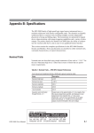
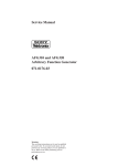
![RUMD User Manual [Version 3.0]](http://vs1.manualzilla.com/store/data/005734566_1-539a984f38202face31c4a646ef91457-150x150.png)