1
Advance / Advance Plus
Installer manual
Introduction
This manual is intended for use by the installer of the ventilation
system. It contains important information concerning installation,
use, maintenance and troubleshooting for the ventilation system.
The installer is responsible for installing and commissioning the
ventilation unit.
The following definitions are used in this manual to draw attention
to hazards, instructions or indications related to people, products,
installations and/or the surroundings.
ä Warning!
Indicates a hazard that can cause injury and/or severe damage
to the product, system or surrounding area.
ä Caution!
Instructions important for the installation, functioning, operation
or maintenance of the product. Failure to observe these
instructions can result in minor injury and/or severe damage to
the product, system or surrounding area.
Note
Instructions important for the installation, functioning, operation
or maintenance of the product. Failure to observe these
instructions can result in minor damage to the product, system
or surrounding area.
Tip
Instructions that may be important for the installation,
functioning, operation or maintenance of the product, but are
not related to injury or material damage.
Tip
Do not forget to register the product via the Heatrae Sadia
website. (www.heatraesadia.com/warranty_registration)
Although this manual has been drawn up with the utmost care, no
rights may be derived from this document.
Heatrae Sadia reserves the right to modify products and manuals
without prior notice.
Due to our continuous product improvement process, the
illustrations in this document may not match the delivered product.
The latest version (if available) can be downloaded from our
website via www.heatraesadia.com.
3
Contents
1. Safety and other regulations
5
2. Product information
7
2.1.
Models
2.2.
Accessories
7
7
2.3.
Technical specifications
8
8
2.4.
Capacity
2.5.
Technical drawings
2.6.
Parts
10
2.7.
Controls
11
3. Installation
9
13
3.1.
Installation requirements
13
3.2.
Installing the ventilation unit
13
3.3.
Connecting the condensate drain
21
3.4.
Connecting the ducts
22
3.5.
Electrical connection
23
4. Operation
24
4.1.
Control options
24
4.2.
RF-VI wireless remote control
24
4.3.
Wireless control switch with timer
25
4.4.
Wireless control switch with automatic control/
26
timer
4.5.
Wired three-position switch
26
4.6.
Pairing and unpairing RF remote controls
27
4.7.
Pairing and unpairing RF sensors
27
5. Commissioning
28
5.1.
Preparation
28
5.2.
Putting into service
28
5.3.
Adjusting the capacity
29
6. Inspection and maintenance
30
6.1.
Inspection and maintenance schedule
30
6.2.
Check for unusual noises
31
6.3.
Inspecting and cleaning the fan
31
6.4.
Inspecting and cleaning the bypass valve
32
6.5.
Inspecting, cleaning and replacing filters
34
6.6.
Maintenance
35
6.7.
RF remote control maintenance
35
6.8.
Inspection of additional RF sensors
35
6.9.
Inspecting and cleaning air valves
35
6.10. Inspecting/cleaning ducts
35
7. Faults
36
8. Service parts
40
9. Warranty
42
10. Declarations
43
4
1. Safety and other regulations
ä
Warning!
●
The specifications and settings of the
ventilation system comply exclusively with
the standards and statutes of the country
in which the ventilation system is sold.
Applications outside this country can lead
to very dangerous situations.
●
The entire system must comply with the
current regulations as referred to in this
document and other applicable
documents provided by the manufacturer.
●
●
All supplements, amendments and
regulations effective at the time of
installation are applicable for all
regulations.
After installation, no health, safety or
environmental risks may be present in
accordance with the applicable CE
standards. This also applies to other
products included in the system.
●
Do not use the product for purposes other
than those for which it is intended, as
described in this manual.
●
Be careful when using electrical
appliances:
-
Never touch the appliance with wet
hands.
-
Never touch the appliance when
barefoot.
●
This product and/or system may be
operated safely by children aged 12 years
and older and by people with physical,
sensory or mental disabilities or a lack of
experience/knowledge if under
supervision or after having received
instructions regarding safe use, and if they
are aware of the product and/or system
hazards.
●
Cleaning and maintenance by the user
may not be done by children or people
with physical, sensory or mental
disabilities or a lack of experience/
knowledge without supervision.
●
Do not allow children to play with the
product and/or system.
●
Do not use the product in the vicinity of
flammable or volatile substances such as
alcohol, insecticides, petrol etc.
●
Work may solely be performed on the
system by Heatrae Sadia or recognised
installers in accordance with the provisions
laid down in this manual. Only original
accessories and parts produced by the
manufacturer may be used for these
purposes.
●
The system includes parts which may be
live. The installer should take the following
steps before carrying out work on an open
system:
-
Disconnect power to the appliance or
system by unplugging the power cord
at the wall socket.
5
-
Secure the appliance or system against
being switched on accidentally.
-
The appliance includes moving parts.
When the plug is removed from the
wall socket, these parts will continue
moving for a few seconds. Therefore,
you should wait a minimum of 10
seconds before opening the appliance
after removing the plug.
ä Important!
●
The safety instructions must be followed in
order to prevent physical injury and/or
damage to the product.
●
Maintenance instructions must be
followed to prevent damage and
excessive wear and tear.
●
The product may not be modified.
●
The product is only suitable for use with a
230 V, 50 Hz AC power supply system.
●
Ensure that the electrical system to which
the product is connected meets the
necessary conditions.
●
Do not expose the product to the
elements.
●
Do not place any objects on top of the
device.
●
Inspect the product regularly for faults. In
the event of faults, immediately contact
your installer or Heatrae Sadia.
●
Switch the product off if:
-
The product is not working properly.
-
You want to clean the outside of the
product.
●
Ensure that the electrical circuit does not
become damaged.
●
Do not use the device to extract air from
boilers, heating systems etc.
6
●
Ensure that the device drains into a sewer
system which leads outside, and is
suitable and installed for this purpose.
●
Ensure that air valves and grilles are not
obstructed, and that they are clean.
●
Watch out for sharp and protruding duct
sections during periodic cleaning of air
valves and grilles.
2. Product information
The Advance and Advance Plus consist of a central balanced
ventilation unit with a heat recovery system and a duct connection
set. The Advance Plus is also equipped with an automatic bypass
valve. The operation of the bypass valve is described under Bypass
control on page 12.
2.1. Models
Models
Item
Type
Description
95060001
Advance
Balanced ventilation unit with heat
95060007
Advance Plus
recovery
Balanced ventilation unit with heat
recovery and bypass valve
2.2. Accessories
Accessories
Item no.
Type
Description
95970200
RF-VI
Wireless RF-VI remote with LED signals,
TRANSMITTER
three modes and timer function
RFT-
Wireless RF control switch with three
TRANSMITTER
settings and a timer function (White)
95970003
W
95970204
RFT-AUTO CO2 RF control switch with two positions,
95970002
HRS-3I C
95970201
RF-CO2
230 V RF CO2-sensor
95970203
RF-RH [BAT]
RF-RH battery-powered sensor
95970202
RF-PIR
RF-PIR battery-powered presence sensor
automatic and timer functions
Conventional wired switch with three
settings
7
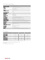
2.3. Technical specifications
Advance/Advance Plus
Dimensions (H x W x D)
760 x 597 x 290 mm
Weight
12 kg (including duct connection set)
Installation
2x 6 mm screws (not provided); on wall/ceiling/floor with min. load-bearing
Housing
IP 30, double-insulated
Housing and insulation
EPP housing (grey), PP hollow-core panel (internal), foamed PVC faceplates
capacity 200 kg/m2
(white)
Duct connection parts /
PP (black)
condensate drain
Motor module
HIPS (black)
Filter caps
TPE (RAL 7040)
Mounting brackets
Galvanised steel
Filter class
Standard G3 (dust filter for the first three months), then replace with G4 or F7
Duct nozzles (4x)
Ø 125 mm, top side, with leak-safe seals
Heat exchanger
Plastic counterflow exchanger (PS), not removable
Thermal efficiency
Up to 91%
Condensate drain (2x)
Ø 14 mm OD, PVC condensate hose (1 m), included
Temperature sensors
1x outside air temperature sensor; 1x exhaust air temperature sensor
Bypass
control*
Automatic control with built-in bypass valve on extraction side, 100%
Frost control
Automatic frost protection (reduce fan speed at temperatures below -1°C)
Motor (1x)
DC (CE) 120 W
Impellers (2x)
PA plastic (backward curved)
Maximum power consumption
90 W
Power supply
230 V, 50 Hz, 4-wire power cable
Cable length
1.5 m (RAL 7001)
RF (built in)
100 m in free space, 868 MHz
Manual
The user manual can also be placed in the bottom corner of the unit
*
Applies exclusively to Advance Plus
2.4. Capacity
Capacity [m3/h]
Pressure [Pa]
Power [W]
Mode 1 minimum
25
12
4
Mode 1 standard
50
17
6
Mode 1 maximum
75
38
13
Mode 2 *
100
70
26.5
Mode 3 minimum
75
38
13
Mode 3 standard
125
104
44
Mode 3 maximum
150
150
72
Mode 3 maximum
175
100
78
*
Mode 2 is a calculated value, depending on the set minimum and maximum capacity.
Mode 1 and 3 can be adjusted using the potentiometers on the
motor module.
(see Adjusting the capacity on page 29).
8
2.5. Technical drawings
122
2
>150 (1)
76
132
76
1
230V
3
86
597
86
>50 (1)
> 150 (1)
760
>50 (1)
425
4
B
A
5
290
>360 (1)
5
(1) Minimum clearance around the ventilation unit
Number
Description
1
Exhaust air to outside
2
Exhaust air from dwelling
3
Supply air from outside
4
Supply air to dwelling
5
Condensate drain (2x)
9
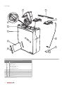
2.6. Parts
2
4
5
10
3
1
6
7
9
8
Main components of Advance and Advance Plus
Number
*
Description
1
Ventilation unit
2
Motor module
3
Duct adapter EPP side
4
Mounting bracket
5
Duct adapter duct side
6
Wire bracket
7
Filter
8
Filter cap
9
Ceiling mounting bracket
10
Bypass valve *
Applies exclusively to Advance Plus
10
2.7. Controls
The Advance and Advance Plus come as standard with threeposition control which allows the flow rates at low and high speed
to be adjusted as desired with the potentiometers on the unit. It is
also possible to pair RF sensors with the ventilation unit for
automatic ventilation control. In addition, the ventilation units have
some controls that operate continuously in the background.
The Advance Plus also has a bypass control which controls the
bypass valve (see Bypass control on page 12).
This sensor measures the relative humidity in the room. The sensor
translates this relative humidity value into a ventilation demand and
communicates this wirelessly to the ventilation unit with which the
sensor is paired, or to a DF/QF controller with the room where it is
registered. This allows ventilation to be continuously and
automatically adjusted, and it ensures that a good indoor climate is
achieved in the most effective and energy efficient manner.
This sensor can be used for "bathroom control", which causes the
ventilation capacity to be increased quickly when there is a sudden
rise in relative humidity (for example during showering). Another
option is "washroom control", which causes the ventilation capacity
2.7.1. Optional sensors
to increase gradually in response to rising relative humidity.
A number of optional RF sensors are available for the Advance and
is automatically decreased.
Advance Plus. When the ventilation unit is in Auto mode, the
capacity is adjusted continuously and automatically.
As soon as the relative humidity has fallen sufficiently, the capacity
RF-PIR sensor
RF CO2 sensor
To ensure a healthy indoor climate and to prevent unpleasant
To ensure a healthy indoor climate and to prevent the air in the
ventilation when people are present.
dwelling from becoming stale, it is important that the CO2 (carbon
dioxide) concentration does not become too high.
The sensor can be placed in any room (except the bathroom), but
should preferably be placed in the living room or bedroom.
odours in the dwelling, it is important that there is enough
The RF-PIR sensor can be placed in any room, for example in the
toilet or in a bathroom with a toilet.
The sensor detects the presence (or absence) of people in the room
and communicates this wirelessly to the ventilation unit with which it
The sensor measures the CO2 concentration in the room. It
is paired. If the ventilation unit is in Auto mode, the capacity is
translates this CO2 concentration into a ventilation demand and
continuously and automatically adjusted.
communicates this wirelessly to the ventilation unit paired with the
If the sensor detects movement, the ventilation system runs at
sensor. This allows ventilation to be continuously and automatically
adjusted, and it ensures that a good indoor climate is achieved in
the most effective and energy efficient manner.
This sensor can be used for "living area control", which causes the
increased capacity for a defined period. If the sensor detects
continuous occupancy of the room, the capacity will be increased
even more. If the motion sensor does not detect any movement
within a set period, the capacity will automatically be decreased
ventilation capacity to be increased gradually in response to a rising
again.
CO2 concentration. A "sleeping area control" is also available. In
This allows ventilation to be continuously and automatically
this mode the ventilation capacity is increased more quickly in the
adjusted, and it ensures that a good indoor climate is achieved in
event of rising CO2 concentration because the extraction points are
the most effective and energy efficient manner.
generally further away from the sleeping area.
In addition, the user can choose between ECO or COMFORT mode
on the sensor. In COMFORT mode the system starts increasing the
capacity at relatively low CO2 concentration, resulting in more
ventilation.
Once the CO2 concentration has fallen sufficiently, the capacity is
automatically decreased.
RF-RH sensor
To ensure a healthy indoor climate and to prevent patches of damp
and mould in the dwelling, it is important that the relative humidity
does not stay high for too long.
The RF-RH sensor can be placed in any room, but preferably in the
bathroom and/or washroom.
11
2.7.2. Bypass control
Solely the Advance Plus is equipped with a bypass valve in the
exhaust air line. This makes it possible to control what happens to
the (warm) exhaust air from the dwelling.
When the valve is in the normal position (closed), the exhaust air
from the dwelling passes through the heat exchanger and
exchanges heat with the cold supply air from outside.
If the valve is opened, the exhaust air no longer passes through the
heat exchanger, so there is no heat exchange. Although the outside
air still passes through the exchanger, the supplied outside air is
not warmed. This is desirable when it is warmer inside than outside
in the summer.
If in the summer it is cooler inside than outside, it is desirable to
cool the incoming air ("cold recovery"). In this case, the valve is
closed so that the relatively cool indoor air again passes through
the exchanger.
The position of the bypass valve is automatically determined using
the measured outdoor temperature and the measured exhaust air
temperature.
2.7.3. Frost control
The Advance and Advance Plus have an automatic control which
protects the heat exchanger against freezing. If the measured
outside air temperature is lower than -1°C, the fan is gradually
slowed down and eventually brought to a standstill. In this case, the
unit will still respond to the timer (see "Operation"). The ventilation
unit also checks whether the temperature has risen sufficiently for
the fan to be switched back on.
Note
If the ventilation unit must continue running when the outside
temperature is lower than -1°C in order to ensure sufficient
ventilation, Heatrae Sadia advises using an external heater in the
supply duct for outside air. The temperature setpoint for this
must be -1°C.
2.7.4. Dirty filter control
The control of the Advance and Advance Plus uses a smart counter
to keep track of when the filters need to be cleaned or replaced.
This counter takes into account air quality, the service life of the
filter and the fan speed. If the system detects that a filter is dirty,
the ventilation unit sends a wireless message to this effect. This
message can be displayed on specific paired devices, such as the
RFT-L or the RF-VI (ventilation interface).
12
3. Installation
3.1. Installation requirements
ä Caution!
In order to prevent condensation, the duct from outside and the
duct leading outside must be thermally insulated and vapour-
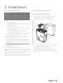
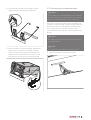
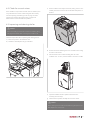
3.2. Installing the ventilation unit
3.2.1. Unpacking and checking
a) Carefully remove the appliance from the box. If necessary, use
the handle on top of the motor module to remove the
tight right up to the ventilation unit.
ventilation unit from the box in an upright position.
Take the following into account when positioning the system:
●
Install the ventilation unit:
-
in a closed area (where the system can cause as little noise
disturbance as possible);
-
in a frost-free area;
-
in the vicinity of a 230 V AC 50 Hz power point; the length
of the power cable is 1.5 m;
-
in the vicinity of a trap with a sewer connection (for
connecting the condensate drain);
-
by mounting it on a wall/ceiling/floor with sufficient loadbearing capacity (min. 200 kg/m2).
●
When positioning the ventilation unit, ensure that you also
leave enough space for servicing the system.
For this purpose, a minimum of 150 mm clearance should be left at the
top and bottom of the unit, and 350 mm at the front (see Technical
drawings on page 9).
●
The duct system and the outlet and inlet points must be
correctly dimensioned.
●
The correct fixing materials must be available.
Tip
In order to avoid noise complaints, Heatrae Sadia advises fitting
silencers on the ducts from and to the dwelling rooms.
b) Check that the nameplate information and the type correspond
to the sticker on the outside of the box.
c)
Check the appliance for damage and completeness.
d) Check that user and installer manuals, a ceiling mounting
bracket and a condensate hose are included with the ventilation
unit.
13
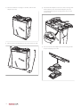
e) Place the ventilation unit upright on the floor, with the duct
adapters at the top.
g) Unlock both duct adapters on the front of the unit using a flathead screwdriver. Then remove both adapters, which are
connected together by the mounting bracket, from the unit
simultaneously.
2x
f)
Remove the two wire brackets from the unit and set them aside.
h) Then remove both duct adapters from the mounting bracket
and put everything to one side.
14
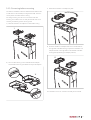
3.2.2. Mounting positions
ä Caution!
The ventilation unit can be mounted on the wall, floor or ceiling.
Depending on the configuration of the ducts, the ventilation unit
Mount the ventilation unit on a concrete surface, not on a
can be wall mounted with the standard duct adapter
wooden or plaster surface or a surface with insufficient load-
arrangement (as delivered) or the inverse arrangement (see
bearing capacity (<200 kg/m2), since that may lead to excessive
Converting before mounting).
noise.
The standard arrangement is always used for floor mounting, and
the inverse arrangement must always be used with ceiling
ä Caution!
Always ensure that the ventilation unit is installed with the ducts
connected to the correct air inlets and outlets.
mounting. This is due to condensation water path in the heat
exchanger.
The symbols on the ventilation unit indicate which ducts should
be connected to which openings.
ä Caution!
If the ventilation unit is mounted "inversely", the duct adapters
must be swapped.
15
Mounting positions
Wall mounting, standard
Wall mounting, inverse 1
A
B
Floor mounting, standard
Ceiling mounting, inverse 1
A
B
1
See Converting before mounting on page 17.
16
Exhaust air to outside
Exhaust air from dwelling
Supply air from outside
Supply air to dwelling
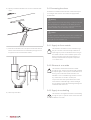
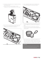
3.2.3. Converting before mounting
c)
Rotate both ventilation unit adapters by 180°.
The Advance and Advance Plus are delivered as standard with the
air inlet ducts on the wall side (mounting bracket side). This is the
II
correct position for wall and floor mounting.
For ceiling mounting, or if this is more convenient with wall
mounting, the ventilation unit can easily be inverted. If this is not
necessary, the following section can be ignored.
I
a) Pull both ventilation unit adapters out of the EPP housing.
I
II
d) Press the ventilation unit adapter that was on the left side into
the right side of the EPP housing, and press the ventilation unit
adapter that was on the right side into the left side of the EPP
housing (thereby switching the adapter positions).
II
b) There is a blue seal ring on the underside of each adapter.
Check whether these rings are fitted correctly to the adapters.
I
II
I
The ventilation unit is now "inverted" and ready to be mounted.
17
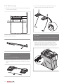
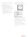
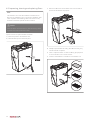
3.2.4. Wall mounting
c)
a) Attach the mounting bracket to the wall using anchor plugs and
Hook the two wire brackets onto the outside of the duct
adapters using the holes intended for this purpose.
>170 (1)
6 mm screws (not provided).
(575)
>125 (1)
425 (2)
>125 (1)
>920 (1)
2x
(1) Minimum clearance around the ventilation unit
(2) Distance between hole centres
ä Caution!
There is only one way to insert the ventilation unit adapters into
the duct adapters.
d) Place the ventilation unit in the wire brackets, tilted forward
slightly. There are recesses on the underside of the EPP
housing into which the wire brackets fit exactly. When the
adapters have been fully inserted into one another, you will
hear a distinct click. This means the unit is firmly attached.
ä Caution!
Ensure that the mounting bracket is mounted horizontally and
level for proper condensate drainage.
b) Slip the duct adapters back over the mounting bracket and
push the two adapters to the left and to the right as far as they
will go.
18
2x
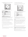
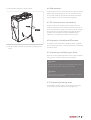
3.2.5. Ceiling mounting
b) Slip the duct adapters back over the mounting bracket and
push the two adapters to the left and to the right as far as they
will go.
ä Caution!
With this mounting option, the ventilation unit needs to be
mounted with enough tilt to ensure correct condensate
drainage. It is also important to ensure that the condensate
hose can be mounted with a slope from the ventilation unit to
the condensate drain.
a) Attach the mounting bracket and the ceiling bracket to the
>170 (1)
ceiling using anchor plugs and 6 mm screws (not provided).
Place the ventilation unit in the ceiling mounting bracket, tilted
forward slightly. There is a recess on the underside the EPP
housing into which the bracket fits exactly.
(575)
> 125(1)
50
>920 (1)
425 (2)
760
>125 (1)
c)
1 Minimum clearance around the ventilation unit
2) Distance between hole centres
d) Tilt the ventilation unit backwards so that the ventilation unit
adapters slide under the duct adapters. When the adapters
have been fully inserted into one another, you will hear a
distinct click. This means the unit is firmly attached.
ä Caution!
There is only one way to insert the ventilation unit adapters into
the duct adapters.
19
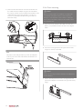
3.2.6. Floor mounting
e) Now secure both wire brackets. First hook each bracket onto
ä Caution!
the outside of the duct adapter using the holes intended for
this purpose, and then clip the underside of the bracket into the
underside of the housing of the ventilation unit. There is a
With this mounting option, the ventilation unit needs to be
recess on the underside of the EPP housing into which the
mounted with enough tilt to ensure correct condensate
bracket fits exactly.
drainage. It is also important to ensure that the condensate
hose can be mounted with a slope from the ventilation unit to
2x
the condensate drain.
2x
a) Attach two wooden laths (50 x 100 x 600 mm and 50 x 50 x
600 mm, not provided) to the floor as shown in the diagram
50
50
100
50
50
below.
580
b) Secure the mounting bracket to the higher of the two laths
using 6 mm screws (not provided).
Note
The position of the ceiling bracket may need to be readjusted.
To do so, loosen the screws a little and shift the bracket in the
oversize holes.
ä Caution!
There is only one way to insert the ventilation unit adapters into
the duct adapters.
c)
Slip the duct adapters back over the mounting bracket and
push the two adapters to the left and to the right as far as they
will go.
20
d) Hook the two wire brackets onto the outside of the duct
3.3. Connecting the condensate drain
adapters using the holes intended for this purpose.
ä Caution!
2x
If the ventilation unit is situated outside the thermal shell of the
dwelling (for example in a non-insulated attic), the condensate
drain must be thermally insulated up to the ventilation unit.
During winter, moisture in the exhaust air from the dwelling may
condense in the heat exchanger. The EPP housing therefore has a
built-in drip tray with two condensate drain ports. With ceiling or
floor mounting, the lower condensate drain port must be
connected. With wall mounting, either condensate drain port can
be used.
ä Caution!
Ensure that the condensate hose is mounted with a downward
slope toward the drain.
ä Caution!
e) Place the ventilation unit in the wire brackets, tilted forward
slightly. There are recesses on the underside of the EPP
housing into which the wire brackets fit exactly. When the
The condensate hose should not have any sharp kinks in it.
a) Open the condensate drain by pulling on the tab.
adapters have been fully inserted into one another, you will
hear a distinct click. This means the unit is firmly attached.
2x
21
b) Slip the provided condensate hose over the condensate drain
nozzle.
3.4. Connecting the ducts
The Advance and Advance Plus have four nozzles at the top for
connecting Ø 125 mm ducts. The nozzles are equipped with
Leaksafe seals.
ä Warning!
When using the unit in multi-unit housing, it must be ensured at
all times that there is no backflow into the dwelling from the
central exhaust air duct. In this case, a mechanical check valve
must be installed in the air outlet duct of the unit.
ä Caution!
In order to prevent condensation, the duct from outside and the
duct leading outside must be thermally insulated and vapourtight right up to the ventilation unit.
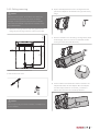
3.4.1. Supply air from outside
c)
Route the condensate hose to a trap with a water level of least
The ventilation unit draws in air from outside through
50 mm. Ensure that the hose is inserted deep enough into the
this port. This duct must be thermally insulated and
trap (minimum 30 mm below water surface).
vapour-tight to prevent condensation from forming on
the outside of the duct. If the ventilation system must
keep running during winter (for frost protection), an
external pre-heater with its temperature setpoint at
-1°C must be used.
3.4.2. Exhaust air to outside
The ventilation unit feeds the exhaust air outside
through this port. This duct must be thermally insulated
and vapour-tight in order to prevent condensation from
forming on the inside and outside of the duct. It is
advisable to use a roof feedthrough that does not let in
any condensation or rainwater. If it does, the
> 50 mm
components of the duct system between this outlet
nozzle and the roof feedthrough must be watertight.
Any condensation water will be discharged through the
condensate drain of the unit.
3.4.3. Supply air to dwelling
d) Fill the trap with water.
The ventilation unit supplies warmed air to the dwelling
through this port. For optimal comfort a silencer should
be fitted on this nozzle.
22
3.4.4. Exhaust air from dwelling
The ventilation unit draws exhaust air out of the
dwelling through this port. This duct does not normally
need to be thermally insulated. Thermally insulated and
vapour-tight ductwork is only necessary if the ventilation
unit is located outside the thermal shell of the dwelling
(for example in a non-insulated attic). For optimal
comfort a silencer should be fitted on this nozzle.
N
L1
B
M
3.5. Electrical connection
The ventilation unit has a four-wire cable. The ventilation unit is
B
double insulated and is therefore not earthed.
M
L
If the HRS-3 wired three-position switch is used for speed control,
connect the wires as shown in the diagram below.
230V
N
50 Hz L1
Wire
Colour
Mode
Functio
Connection
n
N
L1
B
N
blue
—
neutral
mains supply
L1
brown
low
phase
mains supply / switch
L
brown
—
switch
switch/unit
M
grey
medium/
switch
switch/unit
switch
switch/unit
M
auto
B
black
high
2
230V N
50 Hz L1
C
1
If another type of wired switch is used for speed control, connect
the wires as shown in the diagram below.
23
4. Operation
4.1. Control options
4.2. RF-VI wireless remote control
The ventilation unit has several pre-programmed modes. A number
This RF-VI wireless remote control always displays the status of the
of control switches are available for actively setting the correct
ventilation unit with which it is paired.
mode/ventilation capacity:
Wireless RF-VI remote control with LED indicator for status and
●
RF - VI
ventilation functions
Wireless RF control switch with three settings and a timer
●
function
Wireless RF control switch with two settings, an automatic
●
setting and a timer function
●
Conventional wired switch with three settings
●
A combination of the above options.
For pairing or unpairing a wireless RF remote control with/from the
unit, consult Pairing and unpairing RF remote controls on page 27
Note
Do not attach wireless control switches to metal surfaces. This
The three-colour LED (Status) on the RF-VI indicates the status of
the ventilation unit.
●
Red (continuously blinking once per second) = RF-VI not paired
●
Red (continuously blinking in error code pattern) = Ventilation
can interfere with the wireless control switch or cause it to stop
unit is reporting an error (see error code table in the RF-VI
working entirely.
Note
The wireless control switches have a range of 100 metres in free
space (no obstacles). The distance at which the switch can
manual)
●
Orange (continuously on) = Dirty filter
●
Green (continuously on) = No errors, filter okay (everything in
order)
White (continuously blinking once per second) = The RF-VI is
●
paired but has not been in communication with the ventilation
function properly is reduced depending on the obstacles
unit for one hour
interfering with the signal.
If you press and hold the touch button for 10 to 12 seconds * during
Note
When using a wireless control switch in the bathroom, it should
not be located in zone 0 (floor of the shower base) or zone 1 (up
to 2.5 metres above the shower base) due to the effects of
moisture.
normal operation (until the three-colour LED flashes orange), the
RF-VI sends a "Reset dirty filter" message (3 times).
*
If the button is held for longer than 12 seconds, the three-colour LED will go
dark and nothing will happen.
The user can switch between ventilation modes by pressing the
touch button. Each time it is pressed, the mode switches to the next
ä Caution!
If the fan runs at high speed when low speed is selected or at
one in the cyclical order shown below. The corresponding LED is lit
(green).
Activity
Meaning
On
Ventilation unit in Mode 1
On
Ventilation unit in Mode 2
See Faults on page 36 for possible causes of problems and
On
Ventilation unit in Auto Mode
potential solutions.
On/
Ventilation unit is in Mode 3 or
blinking
Timer Mode *
LED
low speed when high speed or timer mode is selected, the
ventilation unit is faulty.
Above signals
Ventilation unit is in Not at
off
Home Mode
On
On
24
Frost control of the ventilation
unit is active
Bypass control of the ventilation
unit is active **
* When timer mode is selected, the corresponding LED blinks for 10 seconds
in a particular pattern (see RF-VI manual) and then stay lit continuously
**
Only applies to Advance Plus
4.3. Wireless control switch with timer
This wireless RF control switch can easily be placed in any room by
applying double-sided tape to the back of the switch.
Usually, the RF-VI interface is always switched on. The interface can
also be switched off for normal operation, and all LEDs
automatically go out after this is done.
●
If the touch button is held for 5 seconds during normal
operation (the RF-VI has been on for more than 2 minutes), all
LEDs will go out and the interface will be switched off.
●
If the interface is off and the touch button is pressed briefly, the
active LEDs will light up for 10 seconds, after which the interface
will switch off again.
●
If the interface is off and the touch button is pressed for 5
seconds, the interface will switch on again and the ventilation
unit information will be displayed.
●
This wireless control switch allows you to select the ventilation
speed (capacity) of the unit:
Error messages and the dirty filter message are always
Level 1, low speed; when one person is
displayed, regardless of whether the interface is on or off.
●
present during the day or night, or when no-
The interface setting (on or off) is recorded in the memory of
one is present.
the RF-VI.
Level 2, medium speed; during the day or
night when more than one person is present.
Level 3, high speed; during cooking,
showering or bathing, or when a lot of people
are present.
Timer; high speed for switching the unit to
high speed for an adjustable period.
High speed remains active for a maximum of 24 hours, after which
the unit switches back to medium or low speed, depending on
which of these was selected last.
Once the timer has run out, the unit switches back to the last
selected speed before the timer was started, unless that was high
speed. In that case the unit switches back to medium or low speed,
depending on which of these was selected last.
The duration of the timer can be set as follows:
●
Press the timer button once: 10 minutes at high speed
●
Press the timer button twice: 20 minutes at high speed
●
Press the timer button three times: 30 minutes at high speed.
The timer can be stopped at any time by pressing the button for
low, medium or high mode.
25
4.4. Wireless control switch with automatic
control/timer
4.5. Wired three-position switch
This control switch is connected directly using connecting wires.
The wired control switch can be combined with one or more
wireless control switches.
This wireless control switch allows you to select the ventilation
speed (capacity) of the unit:
Auto setting, automatic mode; sensor-based
control (CO2, RV and/or PIR). The capacity is
regulated between low and high.
Level 1, low speed; when one person is
present during the day or night, or when no-
Using the wired three-position switch, the unit can be put into three
different ventilation modes (capacities) by turning the switch:
Level 1, low speed; when one person is
1
one is present.
one is present.
Level 3, high speed; during cooking,
showering or bathing, or when a lot of people
are present.
Timer; high speed for switching the unit to
2
the unit switches back to medium or low speed, depending on
which of these was selected last.
Once the timer has run out, the unit switches back to the last
selected speed before the timer was started, unless that was high
speed. In that case the unit switches back to medium or low speed,
Level 2, medium speed; during the day or
night when more than one person is present.
Level 3, high speed; during cooking,
3
showering or bathing, or when a lot of people
are present.
high speed for an adjustable period.
High speed remains active for a maximum of 24 hours, after which
present during the day or night, or when no-
High speed remains active for a maximum of 24 hours, after which
the unit switches back to medium or low speed, depending on
which of these was selected last.
Note
If the wired control switch is combined with a wireless control
depending on which of these was selected last.
switch, there is a risk that the ventilation unit may be set to high
The duration of the timer can be set as follows:
case, the wired switch will indicate high speed when the
by the wired switch and then to low by the wireless switch. In this
●
Press the timer button once: 10 minutes at high speed
ventilation unit is actually running at low speed.
●
Press the timer button twice: 20 minutes at high speed
In order to re-activate the wired control switch in this situation,
●
Press the timer button three times: 30 minutes at high speed.
you should first switch it to another speed.
The timer can be stopped at any time by pressing the button for
low speed, high speed or automatic mode.
Note
Note
For ventilation units with which sensors have been paired (CO2,
RV and/or PIR), Mode 2 operates as an automatic mode.
If sensors have been paired with the ventilation unit, low speed
or high speed will remain active for a maximum of one day, after
which automatic mode will be activated.
Note
If sensors have been paired with the ventilation unit, low speed
or high speed will remain active for a maximum of one day, after
which automatic mode will be activated.
26
4.6. Pairing and unpairing RF remote controls
4.7. Pairing and unpairing RF sensors
4.6.1. Pairing an RF-VI remote control
4.7.1. Pairing RF sensors
Consult the manual supplied with the RF-VI for information on
Pair wireless sensors with the ventilation unit as follows:
pairing this wireless remote control.
a) Disconnect power to the ventilation unit.
b) Wait for at least 15 seconds.
4.6.2. Pairing RF remote controls
c)
Restore power to the ventilation unit.
d) Ensure that a pairing message is sent from the RF sensor within
It is best to pair wireless switches with a ventilation unit in the
two minutes after power to the ventilation unit is switched on.
vicinity of that unit.
For more information, consult the documentation for the
a) Disconnect power to the ventilation unit.
relevant sensor.
b) Wait for at least 15 seconds.
The RF sensor is paired, and the ventilation unit briefly changes the
c)
motor speed to confirm the pairing. The ventilation unit is now
Restore power to the ventilation unit.
d) Within two minutes after powering up the ventilation unit, press
ready to respond to the signals of the wireless sensor.
two diagonally opposite buttons on the RF control switch at the
same time.
The control switch is paired, and the ventilation unit briefly changes
4.7.2. Unpairing RF sensors
the motor speed to confirm the pairing. The ventilation unit is now
RF sensors can only be unpaired at the same time as an RF remote
ready to be operated using the wireless control switch.
control. For more information, see the procedure Unpairing an RFVI remote control or Unpairing RF remote controls on page 27.
4.6.3. Unpairing an RF-VI remote control
Note
Consult the manual supplied with the RF-VI for information on
If several wireless switches, controls and/or RF sensors were
unpairing this wireless remote control.
paired with the unit in question, they must be individually repaired after being unpaired.
4.6.4. Unpairing RF remote controls
It is best to unpair wireless RF remote controls from a ventilation
unit in the vicinity of that unit.
a) Disconnect power to the ventilation unit.
b) Wait for at least 15 seconds.
c)
Restore power to the ventilation unit.
d) Within two minutes after powering up the ventilation unit, press
the four buttons on the control switch at the same time.
The ventilation unit will now no longer respond to the wireless
control switch(es). Unpairing one control switch automatically
unpairs all control switches, controls and RF sensors.
Note
If several wireless switches, controls and/or RF sensors were
paired with the unit in question, they must be individually repaired after being unpaired.
27
5. Commissioning
5.1. Preparation
5.2. Putting into service
Before commissioning
Follow the steps below to correctly put the ventilation unit into
●
The ventilation unit and accessories must be assembled.
service:
●
The duct system must be assembled.
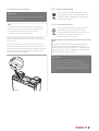
a) Ensure that the ventilation unit has been switched off for 15
●
The condensate drain must be installed and the trap must be
●
filled with water.
All exterior and interior doors and windows must be shut.
c)
There must be enough space for air flow beneath the interior
●
doors.
The adjustable valves in all rooms must be fully opened.
●
seconds.
b) Switch the ventilation unit on again.
ä Caution!
Increasing the maximum motor speed results in increased noise
levels and energy consumption.
Pair available wireless remote controls as described in Pairing
an RF-VI remote control on page 27 or Pairing RF remote
controls on page 27.
d) Pair any available optional sensors as described in Pairing RF
sensors on page 27.
Note
After it is switched on, the ventilation unit remains in pairing
mode for two minutes. During this time, you can pair RF remote
controls. However, during this period the ventilation unit will
ä Caution!
respond to all pairing requests within its range. If several
Before the wireless control switch can be paired, the ventilation
simultaneously, remote controls may unintentionally be paired
unit must have been switched off for 15 seconds.
with all ventilation units. As a result, your ventilation system will
ventilation units located close together are being commissioned
still respond to your own RF remote control, but may also
ä Caution!
respond to that of a neighbouring property.
If the power supply is cut during the commissioning phase, you
ä Caution!
must wait for two minutes after the power has been restored. All
ventilation units in the immediate area will be in pairing mode
for the first two minutes.
If the RF remote control from a neighbouring property is
unintentionally paired with your ventilation system, you can
resolve the problem by switching off your ventilation unit for 15
Note
seconds. Once the ventilation unit has switched on again, you
Every RF remote control and/or RF sensor must be paired
controls. Unpairing one remote control also unpairs all the rest,
separately. You can pair and use up to 20 RF devices.
Note
If you cannot finish pairing RF remote controls and/or RF sensors
within two minutes, then you can put the ventilation unit back
into pairing mode by disconnecting power, waiting 15 seconds,
and then restoring power. Any remote controls already paired
with the ventilation unit will remain paired.
28
must unpair and then re-pair any already paired remote
including those in the neighbouring property.
5.3. Adjusting the capacity
5.3.1. High speed setting
If necessary, adjust the high speed setting with the
ä Caution!
right-hand potentiometer. This potentiometer is set to
The capacities (high and low) of the ventilation unit must be set
125 m3/h by default. The adjustment range goes from
up during commissioning.
75 to 150 m3/h (at 150 Pa).
Note
5.3.2. Low speed setting
If the capacity needs to be increased, first try opening the air
If necessary, adjust the low speed setting with the left-
valves more to see if this helps achieve the required capacity.
hand potentiometer. This potentiometer is set to
Increasing the motor speed results in higher energy
50 m3/h by default and has a lower limit so that it is not
consumption and an increased noise level.
possible to have insufficient ventilation. The
adjustment range is 25 to 75 m3/h.
The high and low speed settings are the same for supply and
exhaust air because both fans in the ventilation unit are driven by
the same motor.
Note
On top of the ventilation unit there are two potentiometers for
The adjustment ranges for low and high speed are chosen so
adjusting the minimum and maximum capacity of the unit, which
means the flow rate at low and high speed. The design calculations
for the system or flow rate measurements will indicate whether
these capacities need to be adjusted.
that the maximum capacity at low speed is the same as the
minimum capacity at high speed. When the low and high speed
settings are the same, there is no difference in capacity between
the three modes (low, medium and high).
ä Caution!
Only adjust the potentiometer for high mode when the
ventilation unit is loaded (connected to a duct system). If you
adjust it when the ventilation unit is unloaded ("free discharge"),
the current consumption may become too high. Current limiting
on the circuit board will then cause irregular and jerky motor
operation.
29
6. Inspection and maintenance
Proper functioning of the ventilation unit, its effectiveness and its
service life can only be assured if the system is inspected and
ä Caution!
maintained in accordance with the provisions below. These
If the ventilation system is being used under harsh operating
provisions are based on normal operating conditions.
conditions or in a very dirty environment, extra maintenance
may be required.
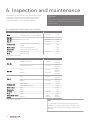
6.1. Inspection and maintenance schedule
Inspection schedule Advance and Advance Plus
Noise
Check for unusual noises coming from
the ventilation unit, air valves and ducts
Filter G3
Filter G4
Check for soiling
Filter F7
Ventilation unit
*
Check for soiling and condensation
leakage
User
Installer
6 months
1 year
1 week
—
9 months
1 year
6 months
1 year
6 months
1 year
Motor module
Check for soiling/imbalance
—
1 year
Bypass valve *
Check functioning and for soiling
—
1 year
Air valves
Check for soiling
3 months
1 year
Ducts
Check for soiling
—
4 years
User
Installer
Only applies to Advance Plus
Maintenance schedule for Advance and Advance Plus
Clean (first 3 months)
1 week
Filter G3
Replace (with G4 or F7)
3 months
Clean
9 months
Replace
18 months
Clean
6 months
Replace
12 months
Clean outside
3 months
Filter G4
Filter F7
Ventilation unit
Where
necessary
Where
necessary
Where
necessary
Where
necessary
Where
necessary
1 year
Clean condensate hose
—
1 year
Motor module
Clean
—
4 years
Bypass valve*
Clean
—
1 year
Air valves
Clean
3 months
1 year
Ducts
Clean
Battery for RF remote
control
*
Where
necessary
Replace
Only applies to Advance Plus
—
8 years
Where
Where
necessary
necessary
Note
It is not possible to remove the heat exchanger from the
ventilation unit. Under normal conditions, and if the correct
filters are used, it should not be necessary to clean the heat
exchanger.
30
6.2. Check for unusual noises
c)
Tilt the ventilation unit away from the wall, ceiling or floor. Then
carefully remove the unit from the wire brackets and place it on
If the ventilation unit produces unusual noises or vibrations, this
the floor.
may indicate that the motor module or bypass valve is faulty.
Consult Inspecting and cleaning the fan on page 31 and/or
Inspecting and cleaning the bypass valve on page 32 to
determine the cause and resolve the problem.
6.3. Inspecting and cleaning the fan
ä Caution!
If the unit is ceiling mounted, be careful to avoid being hit by
swinging wire brackets when removing the ventilation unit.
Follow the steps below when inspecting and cleaning the fan:
a) Disconnect power to the ventilation unit.
b) Unlock the duct adapters using a screwdriver.
d) Unscrew the screws attaching the motor module to the housing
and remove the screws.
e) Take the whole motor module including fans out of the
ventilation unit. To do so, use the handle on the motor module.
2x
f)
Inspect the blades of both impellers and clean them if
necessary (see next step).
g) Clean both fan impellers carefully with a vacuum cleaner.
ä Caution!
When cleaning the fan make sure the balancing clamps have not
been displaced or come loose.
31
h) Check whether the fan is still balanced by spinning one of the
6.4. Inspecting and cleaning the bypass valve
two impellers. If the impellers wobble significantly (and this is
causing noise problems), the entire motor module must be
Note
replaced.
i)
The procedure below only applies to the Advance Plus.
Install the motor module and ventilation unit in reverse order,
and put the ventilation unit back into operation by switching on
the power. If the unit is ceiling mounted, the wire brackets
should be refitted last (also see Ceiling mounting on page 19).
a) Disconnect power to the ventilation unit.
b) Unlock the duct adapters using a screwdriver.
2x
c)
Tilt the ventilation unit away from the wall, ceiling or floor. Then
carefully remove the unit from the wire brackets and place it on
the floor.
ä Caution!
If the unit is ceiling mounted, be careful to avoid being hit by
swinging wire brackets when removing the ventilation unit.
32
d) Unscrew the screws attaching the motor module to the housing
g) Now, carefully pull the bypass valve out of the EPP housing.
and remove the screws.
There are two finger-holes in the valve for this purpose.
e) Take the whole motor module including fans out of the
ventilation unit. To do so, use the handle on the motor module.
h) First clean the bypass valve using a vacuum cleaner to remove
most of the debris. Then you can clean it with a soft brush or a
f)
duster.
Remove the yellow cable bracket from the EPP housing, and
carefully remove the cable from the cable channel.
i)
Check whether the valve can still turn freely by rotating the
valve part. If the valve cannot be moved, the whole bypass valve
must be replaced.
j)
Mount the bypass valve, motor module and ventilation unit in
reverse order, and put the ventilation unit back into service by
restoring power. If the unit is ceiling mounted, the wire brackets
should be refitted last (also see Ceiling mounting on page 19).
ä Warning!
When refitting the bypass valve, make sure that it is pushed
right in until it is flush with the EPP housing. If the valve housing
is protruding, this may obstruct the fan and damage it.
33
6.5. Inspecting, cleaning and replacing filters
c)
Remove the filters from the ventilation unit. There are tabs at
the front of the filters for this purpose.
Note
The ventilation unit comes with G3 filters as standard. These
filters are very suitable for use as "construction dust filters" after
initial completion of the dwelling. After around three months,
these filters should be replaced with G4 or F7 filters.
ä Caution!
G4 and F7 filters can be cleaned once, after which they must be
replaced at the next maintenance interval.
Inspect and clean or replace the filters as follows:
a) Disconnect power to the ventilation unit.
b) Pull both filter caps out of the front panel.
d) Visually inspect the filters for soiling. If the filters are dirty, they
must be cleaned or replaced.
e) Clean or replace the filters. To clean the filters, gently tap them
to remove the dirt or use a vacuum cleaner.
f)
Insert the cleaned filters or new filters in the ventilation unit.
G3
G4
F7
34
g) Put both filter covers back in the front panel.
6.6. Maintenance
The RF-VI remote control is mains powered, so it does not have any
batteries that need to be replaced. The only maintenance to be
done consists of cleaning the outside of the device with a damp
cloth if necessary. Do not use chemical cleaning agents.
6.7. RF remote control maintenance
The RF remote control is battery powered. Under normal use
conditions, the battery has an estimated service life of around 10
years. Once the battery is empty, the remote control will no longer
work, and it will no longer be possible to manually operate the
ventilation unit. At this point, the battery (CR2032) must be
replaced. It is not necessary to re-pair the remote control.
6.8. Inspection of additional RF sensors
For inspection and maintenance of the RF-RH sensor, the RF-PIR
sensor or the RF CO2 sensor, consult the information provided with
h) Put the ventilation unit back into operation by switching on the
the relevant sensor.
power.
6.9. Inspecting and cleaning air valves
Check the air valves regularly (around once every three months) for
soiling. If the air valves are dirty, they must be cleaned.
ä Caution!
When removing or replacing air valves and grilles, watch out for
protruding duct sections. These can be very sharp.
ä Caution!
When cleaning, do not adjust the air valve settings, and replace
the valves in their original ducts.
6.10. Inspecting/cleaning ducts
It is advisable to check the ducts in the housing once every four
years. The ducts must be cleaned once every eight years.
35
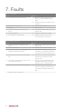
7. Faults
The fan has stopped
Cause
a)
The frost protection system is active.
Solution
●
When the outside temperature rises
above -1°C, the fan will start running
again.
●
Install a pre-heater in the supply duct for
outside air.
b) The power is switched off.
●
Switch the power back on.
c)
●
Restore power.
●
Clean the fan impeller. Watch out for the
No power.
d) The fan is blocked or stuck due to heavy
soiling.
balance clips.
e)
The fan is defective.
●
Replace the entire motor module.
f)
The ventilation unit PCB is faulty.
●
Replace the PCB and carry out the
commissioning procedure again.
The ventilation unit is noisy
Cause
a)
The fan is blocked or stuck due to heavy
Solution
●
soiling.
Clean the fan impeller. Watch out for the
balance clips.
b) The fan is imbalanced.
●
Replace the entire motor module.
c)
●
If the ventilation unit cannot be
The unit is mounted on a wall/ceiling/floor with
insufficient load-bearing capacity.
relocated, try using vibration dampers to
decouple it from the wall, ceiling or floor.
d) The ducts are not correctly connected to the
●
unit.
Check the connections and ensure that
fixed ducts are clamped to the wall,
ceiling or floor.
e)
The second condensate drain is open and not
●
connected (hissing sound).
Close the second condensate drain by
folding back the tab with the plug and
clicking it into the condensate drain.
f)
The bypass valve is blocked (rattling noise). (*)
●
Inspect the valve. Clean it if it has
become blocked with dirt. Replace the
valve if there is a different cause of the
fault.
*
36
Applies exclusively to Advance Plus
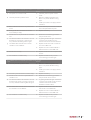
The ventilation unit is not responding to the RF sensors (PIR sensor, 230 V CO2 sensor, RV sensor)
Cause
a)
Solution
The system is not in Auto mode.
●
b) The frost protection system is active.
●
If desired, place the system in Auto
mode.
When the outside temperature rises
above -1°C, the fan will start running
again.
●
Install a pre-heater in the supply duct for
●
Check whether power has been switched
outside air.
c)
With a 230 V RF-CO2 sensor: no power to the
off or interrupted. Restore power.
sensor.
d) If using an RF-RH or RF-PIR sensor: the RF
●
Replace the battery.
●
Restart the commissioning procedure
sensor battery is empty.
e)
The RF sensor is not paired with the ventilation
unit.
f)
The distance between the ventilation unit and
and pair the RF sensor.
●
the RF sensor is too large, or there are too
not work, move the RF sensor to a
many obstacles interfering with the signal.
g) The OEM codes of the RF sensor and the
Try pairing the devices again. If this does
location where there are fewer obstacles.
●
ventilation unit are different.
Replace the RF sensor with one that has
the correct OEM code.
●
Replace the motor module PCB with a
PCB that has the correct OEM code.
h)
The RF sensor is faulty.
●
Replace the RF sensor and re-pair it with
i)
The ventilation unit PCB is faulty.
●
Replace the PCB and carry out the
the unit.
commissioning procedure again.
The ventilation unit is not responding to the RF remote controls
Cause
a)
The frost protection system is active.
Solution
●
When the outside temperature rises
above -1°C, the fan will start running
again.
●
Install a pre-heater in the supply duct for
outside air.
b) The battery of the RF remote control is empty.
●
Replace the battery.
c)
●
Restart the commissioning procedure
The RF remote control is not paired with the
ventilation unit.
d) The distance between the ventilation unit and
and pair the RF remote control.
●
Try pairing the devices again. If this does
the RF remote control is too large or there are
not work, move the RF remote control to
too many obstacles interfering with the signal.
a location where there are fewer
obstacles to interfere with it.
e)
The OEM codes of the RF remote control and
●
the ventilation unit are different.
Replace the RF remote control with one
that has the correct OEM code.
●
Replace the motor module PCB with a
PCB that has the correct OEM code.
f)
The ventilation unit PCB is faulty.
●
Replace the PCB and carry out the
commissioning procedure again.
37
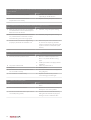
The fan runs at high speed when low speed is selected and at low speed when high speed or timer
mode is selected
Cause
a)
One of the RF sensors has a problem.
Solution
●
See table "The ventilation unit is not
●
Replace the faulty temperature sensor.
responding to the RF sensors".
b) One of the ventilation unit's internal
temperature sensors is faulty.
The fan suddenly starts running much faster or slower (for no apparent reason)
Cause
a)
After using the timer function, the ventilation
Solution
●
If desired, change the system setting.
●
If desired, change the system setting.
●
Disconnect power to the ventilation unit
unit switches back to the last selected speed
before the timer was started.
b) If sensors have been paired with the ventilation
unit, it switches back to automatic mode 24
hours after being set to low or high speed.
c)
The RF remote control from a neighbouring
property is paired with this ventilation unit.
for 15 seconds. Unpair any paired RF
remote controls (and any RF sensors) and
re-pair the remote controls (and any RF
sensors).
The ventilation unit is not responding to the three-position switch
Cause
a)
The frost protection system is active.
Solution
●
When the outside temperature rises
above -1°C, the fan will start running
again.
●
Install a pre-heater in the supply duct for
outside air.
b) The power is switched off.
●
Switch the power back on.
c)
●
Restore power.
●
Connect the switch wires correctly (see
No power.
d) The switch wires of the three-position switch
are connected incorrectly.
e)
The ventilation unit PCB is faulty.
wiring diagram).
●
Replace the PCB and carry out the
commissioning procedure again.
The ventilation unit is leaking water
Cause
a)
The condensate drain is not connected.
Solution
●
Connect one of the two condensate
drains.
b) The condensate drain is blocked.
●
Unblock the condensate drain and try to
identify the cause of the problem.
c)
The second condensate drain is open and not
connected (hissing sound).
●
Close the second condensate drain by
folding back the tab with the plug and
clicking it into the condensate drain.
38
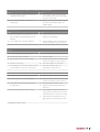
The ducts leading outside are wet (on the outside) and/or are leaking water
Cause
a)
The ducts leading outside are not thermally
Solution
●
insulated or vapour-tight.
Ensure that the ducts that lead outside
are thermally insulated and vapour-tight
over their entire length.
b) The roof feedthrough is not rainproof or
●
vapour-tight.
Replace the existing roof feedthrough(s)
with rainproof and vapour-tight roof
feedthrough(s).
The valves are noisy
Cause
a)
No Heatrae Sadia noise dampening hose has
Solution
●
been installed in the ducts leading into the
Install noise damping hoses on the ducts
leading into the dwelling.
dwelling.
b) The air valves are not correctly adjusted.
●
Put the ventilation unit in commissioning
mode and readjust the system settings.
The air quality in the dwelling is not good / air supply and extraction in the dwelling are not working
properly
Cause
a)
One or both filters are dirty or blocked.
Solution
●
Clean or replace dirty/blocked filters.
b) The valves are dirty or blocked.
●
Clean the valves.
c)
●
Put the ventilation unit in commissioning
The air valves are not correctly adjusted.
mode and readjust the system settings.
d) The fan is not running.
●
See "The ventilator is not running".
e)
●
See "The ventilation unit is not
The ventilation unit is not responding to the RF
sensors (PIR sensor, CO2 sensor, RV sensor).
responding to the RF sensors".
Cold air is being supplied to the dwelling
Cause
a)
The filter in the extraction outlet is blocked.
b) The air valves are not correctly adjusted.
Solution
●
Clean or replace the filter in the air outlet.
●
Put the ventilation unit in commissioning
mode and readjust the system settings.
c)
The bypass valve is in bypass mode when it
●
Clean the bypass valve if it is dirty.
should not be. (*)
●
Replace the entire bypass valve if it is
defective. (*)
d) One of the temperature sensors is faulty.
●
If the supply air temperature sensor is
faulty, replace the wiring harness with the
temperature sensor in the motor module.
●
If the exhaust air temperature sensor is
faulty, replace the entire bypass module.
(*)
* Only applies to Advance Plus
39
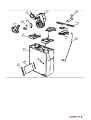
8. Service parts
Service parts
No.
Item number
Description
1
95607724
Entire motor module
2
95615089
Motor module printed circuit board
95607725
Cable harness for motor module with (Advance Plus) outdoor
temperature sensor
3
95970206
Outdoor temperature sensor (Advance)
4
95607827
Power cable
5
95970205
Bypass valve assembly *
95970009
G4 filter set
95970010
F7 filter set
7
95607728
Filter caps, set of 4
8
95607822
Duct adapter EPP side with seals, set of 2
9
95607823
Duct adapters duct side with seals, set of 2
6
10
95607824
Seals for duct-side duct adapter, set of 4
11
95607825
EPP housing with heat exchanger
12
95607727
Wire brackets, set of 2
13
95607726
Ceiling mounting bracket
14
95607826
Mounting bracket
*
40
Applies exclusively to Advance Plus
1
13
4
2
3
14
5
10
8
9
12
11
6
7
41
9. Warranty
The warranty is valid for 2 years after the installation date.
Disclaimer
This warranty does not apply to:
●
Disassembly and assembly costs.
●
Faults which are caused by incorrect treatment.
●
Negligence or accident.
●
Faults that have been caused by repairs by third parties without
authorisation from Heatrae Sadia.
If the appliance does not function correctly or develops a fault
please contact Heatrae Sadia immediately.
Ensure that only genuine spares are used for repairs.
42
10. Declarations
Inbouwverklaring | Déclaration d'incorporation |
Einbauerklärung | Declaration of incorporation
Heatrae Sadia
Voldoet aan de geharmoniseerde Europese normen |
Hurricane Way
Répond aux normes Européennes harmonisées |
Norwich NR6 6EA
United Kingdom
Entspricht den harmonisierten europäischen Normen |
Complies with the harmonized European standard:
●
EN 60335-1:2012 | EN 60335-2-80:2003/A1:2004
EN 60335-2-80:2003/A2:2009
Verklaart dat het product | Déclare que le produit |
Erklärt dass das Produkt | Declares that the product:
-
Ventilation unit with heat recovery
●
EN 60730-1:2012
●
EN 55014-1:2007 | EN 55014-1:2007/C1:2009
EN 55014-1:2007/A1:2009 | EN 55014-1:2007/A2:2010
Advance – 95060001
-
EN 55014-2:1998 | EN 55014-2:1998/C1:1998
Ventilation unit with heat recovery
EN 55014-2:1998/A1:2002 | EN 55014-2:1998/IS1:2007
Advance Plus – 95060007
EN 55014-2:1998/A2:2008
●
EN 61000-3-2:2006/A1:2009 | EN 61000-3-2:2006/A2:2009
Must be considered as a partly completed machine and may not be put into
EN 61000-3-3:2013 | EN 61000-6-1:2007
service until the end machine into which it will be integrated has been
EN 61000-6-3:2007/A1:2011 | EN 61000-6-3:2007/AC:2012
declared as being in conformity with the provisions of the Machinery
Directive 2006/42/EC |
Doit être considéré comme une machine non terminée et ne peut pas être
Norwich, December 1, 2014.
mise en service tant que la machine finale, installée à son emplacement
définitif, n'est pas déclarée conforme aux dispositions des directives relatives
aux machines 2006/42/CE |
Voldoet aan de bepalingen gesteld in de richtlijnen |
Répond aux exigences des directives |
Entspricht den Anforderungen in den Richtlinien |
Complies with the requirements stated in the directives:
-
Low Voltage Directive 2006/95/EC
-
Electromagnetic Compatibility (EMC) Directive
2004/108/EG
-
Directive 2011/65/EU (RoHS)
43
HEATRAE SADIA HEATING
Hurricane Way, Norwich NR6 6EA
www.heatraesadia.com
SERVICE
01603 420100
EMAIL
[email protected]
HS | 36006180 issue 03
01-00111-001 | ID 2015-01-28-1623