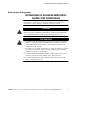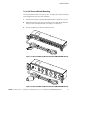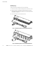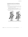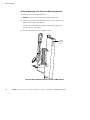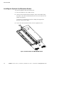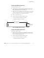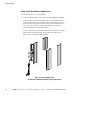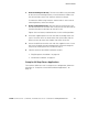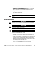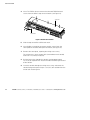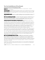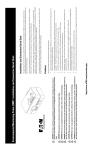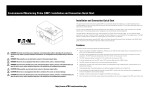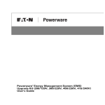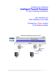
1
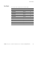
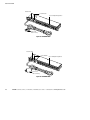
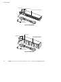
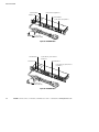
Powerware® Enclosure Power Distribution Unit (ePDUt)
12–24A/120V, 12–32A/240V
User’s Guide
Requesting a Declaration of Conformity
Units that are labeled with a CE mark comply with the following harmonized standards and EU directives:
S
Harmonized Standards: IEC 62040-1-1 and IEC 62040-2; IEC 60950 Third Edition
S
EU Directives:
73/23/EEC, Council Directive on equipment designed for use within certain voltage limits
93/68/EEC, Amending Directive 73/23/EEC
89/336/EEC, Council Directive relating to electromagnetic compatibility (EMC)
92/31/EEC, Amending Directive 89/336/EEC relating to EMC
The EC Declaration of Conformity is available upon request for products with a CE mark. For copies of the EC
Declaration of Conformity, contact:
Eaton Power Quality Oy
Koskelontie 13
FIN-02920 Espoo
Finland
Phone: +358-9-452 661
Fax: +358-9-452 665 68
Eaton and Powerware are registered trademarks and ePDU is a trademark of Eaton Corporation or its subsidiaries
and affiliates. TORX is a registered trademark of Textron Inc.
ECopyright 2005–2007 Eaton Corporation, Raleigh, NC, USA. All rights reserved. No part of this document may be
reproduced in any way without the express written approval of Eaton Corporation.
Special Symbols
The following are examples of symbols used on the UPS or accessories to alert you to important
information:
RISK OF ELECTRIC SHOCK - Observe the warning associated with the risk of electric shock
symbol.
CAUTION: REFER TO OPERATOR’S MANUAL - Refer to your operator’s manual for additional
information, such as important operating and maintenance instructions.
This symbol indicates that you should not discard waste electrical or electronic equipment (WEEE) in
the trash. For proper disposal, contact your local recycling/reuse or hazardous waste center.
Table of Contents
1
Enclosure Power Distribution Unit . . . . . . . . . . . . . . . . . . . . . . . . . . . . . . . . . . . . . . .
1
Safety Warnings . . . . . . . . . . . . . . . . . . . . . . . . . . . . . . . . . . . . . . . . . . . . . . . . . . . . . . . . . . . . . . . . . . . . .
2
Installation . . . . . . . . . . . . . . . . . . . . . . . . . . . . . . . . . . . . . . . . . . . . . . . . . . . . . . . . .
7
Inspecting the Equipment . . . . . . . . . . . . . . . . . . . . . . . . . . . . . . . . . . . . . . . . . . . . . . . . . . . . . . . . . . . . . . .
Checking the Accessory Kit . . . . . . . . . . . . . . . . . . . . . . . . . . . . . . . . . . . . . . . . . . . . . . . . . . . . . . . . . . . . . .
Installing Mounting Brackets . . . . . . . . . . . . . . . . . . . . . . . . . . . . . . . . . . . . . . . . . . . . . . . . . . . . . . . . . . . . .
1U or 2U Recessed Rack Mounting . . . . . . . . . . . . . . . . . . . . . . . . . . . . . . . . . . . . . . . . . . . . . . . . . . . . . .
Wall Mounting . . . . . . . . . . . . . . . . . . . . . . . . . . . . . . . . . . . . . . . . . . . . . . . . . . . . . . . . . . . . . . . . . . . .
0U Rack Mounting (with Factory-Installed Brackets) . . . . . . . . . . . . . . . . . . . . . . . . . . . . . . . . . . . . . . . . . .
0U Rack Mounting (with Universal Mounting Bracket) . . . . . . . . . . . . . . . . . . . . . . . . . . . . . . . . . . . . . . . . .
2U Deep-Recess Rack Mounting . . . . . . . . . . . . . . . . . . . . . . . . . . . . . . . . . . . . . . . . . . . . . . . . . . . . . . . .
Installing the Optional Cord Retention Bracket . . . . . . . . . . . . . . . . . . . . . . . . . . . . . . . . . . . . . . . . . . . . . . . .
Final Setup . . . . . . . . . . . . . . . . . . . . . . . . . . . . . . . . . . . . . . . . . . . . . . . . . . . . . . . . . . . . . . . . . . . . . . . . .
Setup for 1U and 2U Rack-Mount Applications . . . . . . . . . . . . . . . . . . . . . . . . . . . . . . . . . . . . . . . . . . . . . .
Setup for Wall-Mount Applications . . . . . . . . . . . . . . . . . . . . . . . . . . . . . . . . . . . . . . . . . . . . . . . . . . . . .
Setup for Floor-Mount Applications . . . . . . . . . . . . . . . . . . . . . . . . . . . . . . . . . . . . . . . . . . . . . . . . . . . . .
Setup for 0U Rack-Mount Applications . . . . . . . . . . . . . . . . . . . . . . . . . . . . . . . . . . . . . . . . . . . . . . . . . . .
Setup for 2U Deep-Recess Applications . . . . . . . . . . . . . . . . . . . . . . . . . . . . . . . . . . . . . . . . . . . . . . . . . .
Plug-Receptacle Installation . . . . . . . . . . . . . . . . . . . . . . . . . . . . . . . . . . . . . . . . . . . . . . . . . . . . . . . . . . . . .
Hardwired Installation . . . . . . . . . . . . . . . . . . . . . . . . . . . . . . . . . . . . . . . . . . . . . . . . . . . . . . . . . . . . . . . . .
Front Panels . . . . . . . . . . . . . . . . . . . . . . . . . . . . . . . . . . . . . . . . . . . . . . . . . . . . . . . . . . . . . . . . . . . . . . . .
7
7
8
9
10
11
12
13
14
15
15
17
17
18
19
20
21
25
3
Specifications . . . . . . . . . . . . . . . . . . . . . . . . . . . . . . . . . . . . . . . . . . . . . . . . . . . . . . .
33
4
Service and Support . . . . . . . . . . . . . . . . . . . . . . . . . . . . . . . . . . . . . . . . . . . . . . . . . .
41
Two-Year Limited Warranty (US and Canada) . . . . . . . . . . . . . . . . . . . . . . . . . . . . . . . . . . . . . . . . . . . . . . . . .
43
2
EATON Powerware® ePDUt (12–24A/120V, 12–32A/240V) User’s Guide S 164201596 Rev C www.powerware.com
i
TABLE OF CONTENTS
ii
EATON Powerware® ePDUt (12–24A/120V, 12–32A/240V) User’s Guide S 164201596 Rev C www.powerware.com
Chapter 1
Enclosure Power Distribution Unit
The Eaton® Powerware® Enclosure Power Distribution Unit (ePDUt) is
designed to distribute power within a rack. Providing outstanding
performance and reliability, the ePDU’s unique benefits include the
following:
S The ePDU can be installed in one-U (1U) or two-U (2U) applications
(depending on model). The standard mounting bracket allows the
ePDU to be recessed up to 32 mm (1.26”) in the rack.
S All models can be wall-mounted with included hardware and
customer-provided fasteners appropriate to the type of wall.
S All models can be installed in zero-U (0U) applications with included
hardware. The standard mounting bracket allows the ePDU to be
recessed up to 32 mm (1.26”) in the rack.
S All models can be placed on the floor for operation.
S Some models provide load distribution through separate receptacle
groups called segments.
S The indicator LED shows when incoming power is available to the
ePDU.
S All receptacles, circuit breakers, and the indicator LED and power
cord are located on the front panel of the ePDU for easy access.
The following options are available for the ePDU:
S Cord retention bracket for secure power cord retention.
S Universal mounting bracket for mounting the ePDU in a 0U
application, recessed up to 32 mm (1.26”) in the rack or mounted with
hooks instead of fasteners.
S Deep-recess mounting brackets (2U applications only) for mounting
the ePDU up to 89 mm (3.50”) from the front of the rack or in a
wall-mounted application.
EATON Powerware® ePDUt (12–24A/120V, 12–32A/240V) User’s Guide S 164201596 Rev C www.powerware.com
1
ENCLOSURE POWER DISTRIBUTION UNIT
Safety Warnings
IMPORTANT SAFETY INSTRUCTIONS
SAVE THESE INSTRUCTIONS
This manual contains important instructions that you should follow during installation and
operation of the ePDU. Please read all instructions before operating the equipment and save
this manual for future reference.
DANGER
This ePDU contains LETHAL VOLTAGES. All repairs and service should be performed by
AUTHORIZED SERVICE PERSONNEL ONLY. There are NO USER SERVICEABLE PARTS
inside the ePDU.
CAUTION
S To reduce the risk of fire or electric shock, install this ePDU in a temperature and
humidity controlled, indoor environment, free of conductive contaminants. Ambient
temperature must not exceed 45°C (113°F). Do not operate near water or excessive
humidity (95% maximum).
S To comply with international standards and wiring regulations, the total equipment
connected to the output of this ePDU must not have an earth leakage current greater
than 3.5 milliamperes.
S For PERMANENTLY CONNECTED EQUIPMENT, a readily accessible disconnect device
shall be incorporated in the building installation wiring.
S For PLUGGABLE EQUIPMENT, the power outlet shall be installed near the equipment and
shall be readily accessible.
2
EATON Powerware® ePDUt (12–24A/120V, 12–32A/240V) User’s Guide S 164201596 Rev C www.powerware.com
ENCLOSURE POWER DISTRIBUTION UNIT
Consignes de sécurité
CONSIGNES DE SÉCURITÉ IMPORTANTES
CONSERVER CES INSTRUCTIONS
Ce manuel contient des instructions importantes que vous êtes invité à suivre lors de toute
procédure d’installation et de fonctionnement de la ePDU. Veuillez consulter entièrement
ces instructions avant de faire fonctionner l’équipement et conserver ce manuel afin de
pouvoir vous y reporter ultérieurement.
DANGER!
Cet ePDU contient des TENSIONS MORTELLES. Toute opération d’entretien et de réparation
doit être EXCLUSIVEMENT CONFIÉE A UN PERSONNEL QUALIFIÉ AGRÉÉ. AUCUNE PIÈCE
RÉPARABLE PAR L’UTILISATEUR ne se trouve dans la ePDU.
ATTENTION!
S Pour réduire les risques d’incendie et de décharge électrique, installer la ePDU
uniquement à l’intérieur, dans un lieu dépourvu de matériaux conducteurs, où la
température et l’humidité ambiantes sont contrôlées. La température ambiante ne doit
pas dépasser 45 °C. Ne pas utiliser à proximité d’eau ou dans une atmosphère
excessivement humide (95 % maximum).
S Afin d’être conforme aux normes et règlements internationaux de câblage, le courant de
fuite à la terre de la totalité du matériel branché sur la sortie de la ePDU ne doit pas
dépasser 3,5 mA.
S Afin de CONNECTER DE MANIÈRE PERMANENTE L’ÉQUIPEMENT, un dispositif de
déconnexion aisément accessible doit être incorporé au câblage d’installation du
bâtiment.
S En ce qui concerne l’ÉQUIPEMENT ENFICHABLE, la prise d’alimentation doit être
installée près de l’équipement et doit être facile d’accès.
EATON Powerware® ePDUt (12–24A/120V, 12–32A/240V) User’s Guide S 164201596 Rev C www.powerware.com
3
ENCLOSURE POWER DISTRIBUTION UNIT
Sicherheitswarnungen
WICHTIGE SICHERHEITSANWEISUNGEN
AUFBEWAREN
Dieses Handbuch enthält wichtige Hinweise, welche Sie bei der Installation und Wartung
des ePDU beachten sollten. Bitte lesen Sie alle Anweisungen des Handbuches bevor Sie mit
dem Gerät arbeiten. Bewahren Sie das Handbuch zum Nachlesen auf.
WARNUNG
Die ePDU führt lebensgefährliche Spannungen. Alle Reparatur- und Wartungsarbeiten
sollten nur von Kundendienstfachleuten durchgeführt werden. Die ePDU enthält keine vom
Benutzer zu wartenden Komponenten.
ACHTUNG
S Um die Brand- oder Elektroschockgefahr zu verringern, diese ePDU nur in Gebäuden mit
kontrollierter Temperatur und Luftfeuchtigkeit installieren, in denen keine leitenden
Schmutzstoffe vorhanden sind. Die Umgebungstemperatur darf 45°C nicht übersteigen.
Die ePDU nicht in der Nähe von Wasser oder in extrem hoher Luftfeuchtigkeit
(max. 95 %) betreiben.
S Um internationale Normen und Verdrahtungsvorschriften zu erfüllen, dürfen die an den
Ausgang dieser ePDU angeschlossenen Geräte zusammen einen Erdableitstrom von
insgesamt 3,5 Milliampere nicht überschreiten.
S Für PERMANENT ANGESCHLOSSENE GERÄTE: In der Gebäudeverkabelung muss eine
leicht zugängliche Trennvorrichtung enthalten sein.
S Für GERÄTE MIT STECKERN: Die Steckdose muss sich in der Nähe des Geräts befinden
und leicht zugänglich sein.
4
EATON Powerware® ePDUt (12–24A/120V, 12–32A/240V) User’s Guide S 164201596 Rev C www.powerware.com
ENCLOSURE POWER DISTRIBUTION UNIT
Advertencias de Seguridad
INSTRUCCIONES DE SEGURIDAD IMPORTANTES
GUARDE ESTAS INSTRUCCIONES
Este manual contiene instrucciones importantes que debe seguir durante la instalación y el
funcionamiento de la ePDU. Por favor, lea todas las instrucciones antes de poner en
funcionamiento el equipo y guarde este manual para referencia en el futuro.
PELIGRO
Este ePDU contiene VOLTAJES MORTALES. Todas las reparaciones y el servicio técnico
deben ser efectuados SOLAMENTE POR PERSONAL DE SERVICIO TÉCNICO AUTORIZADO.
No hay NINGUNA PARTE QUE EL USUARIO PUEDA REPARAR dentro de la ePDU.
PRECAUCIÓN
S Para reducir el riesgo de incendio o de choque eléctrico, instale este ePDU en un lugar
cubierto, con temperatura y humedad controladas, libre de contaminantes conductores.
La temperatura ambiente no debe exceder los 45°C. No trabaje cerca del agua o con
humedad excesiva (95% máximo).
S Para cumplir con los estándares internacionales y las normas de instalación, la totalidad
de los equipos conectados a la salida de este ePDU no debe tener una intensidad de
pérdida a tierra superior a los 3,5 miliamperios.
S Para EQUIPO CONECTADO PERMANENTEMENTE, se debe incorporar un dispositivo de
desconexión fácilmente accesible al cableado de la instalación del edificio.
S Para EQUIPO ENCHUFABLE, la salida de alimentación debe estar instalada cerca del
equipo y estar fácilmente accesible.
EATON Powerware® ePDUt (12–24A/120V, 12–32A/240V) User’s Guide S 164201596 Rev C www.powerware.com
5
ENCLOSURE POWER DISTRIBUTION UNIT
6
EATON Powerware® ePDUt (12–24A/120V, 12–32A/240V) User’s Guide S 164201596 Rev C www.powerware.com
Chapter 2
Installation
This section explains:
S Equipment inspection
S Enclosure Power Distribution Unit (ePDU) setup and installation
S Front panel diagrams
Inspecting the Equipment
If any equipment has been damaged during shipment, keep the shipping
cartons and packing materials for the carrier or place of purchase and file
a claim for shipping damage. If you discover damage after acceptance,
file a claim for concealed damage.
To file a claim for shipping damage or concealed damage: 1) File with
the carrier within 15 days of receipt of the equipment; 2) Send a copy of
the damage claim within 15 days to your service representative.
Checking the Accessory Kit
The ePDU accessory kit includes the following hardware for mounting in
0U, 1U, or 2U applications:
S Four M5×0.8 mm panel nuts
S Four M5×20 mm hex-head/Phillips screws with integrated
lockwashers and flat washers
If you ordered any separate optional accessories, check that the
following associated hardware is included with the option.
For the cord retention bracket:
S Cord retention bracket
S 15 tie wraps
S Four #6×1/4” pan-head screws
For the universal mounting bracket:
S Universal mounting bracket
S Two M4×8 mm pan-head screws
EATON Powerware® ePDUt (12–24A/120V, 12–32A/240V) User’s Guide S 164201596 Rev C www.powerware.com
7
INSTALLATION
For the deep-recess mounting bracket:
S 2U deep-recess mounting bracket
S Four M4×8 mm pan-head screws
Installing Mounting Brackets
Follow the appropriate instructions according to mounting type:
S 1U or 2U recessed rack mounting
S Wall mounting
S 0U rack mounting (with factory-installed mounting brackets)
S 0U rack mounting (with optional universal mounting bracket)
S 2U deep-recess rack mounting
NOTE If you are installing the ePDU in a flush-mount 1U or 2U application, or placing the
ePDU on the floor, the brackets are factory-installed in their appropriate locations. No further
adjustment to the brackets is necessary.
NOTE The 2U deep-recess rack mounting brackets can be installed as wall mounting
brackets. Follow the instructions for 2U deep-recess rack mounting, but install the brackets
rotated 180 degrees.
8
EATON Powerware® ePDUt (12–24A/120V, 12–32A/240V) User’s Guide S 164201596 Rev C www.powerware.com
INSTALLATION
1U or 2U Recessed Rack Mounting
The recessed dimension is 32 mm (1.26”). To adjust the factory-installed
mounting brackets for recessed mounting:
1.
Remove the factory-installed mounting brackets. Retain the screws.
2.
Align the brackets with the screw holes on the sides of the ePDU in
the recessed mounting location (see Figure 1 or Figure 2).
3.
Secure the brackets with the retained screws.
Figure 1. 1U Recessed Mounting Bracket Adjustment (PW101BA1U001 Shown)
Figure 2. 2U Recessed Mounting Bracket Adjustment (PW103BA2U009 Shown)
EATON Powerware® ePDUt (12–24A/120V, 12–32A/240V) User’s Guide S 164201596 Rev C www.powerware.com
9
INSTALLATION
Wall Mounting
To adjust the factory-installed brackets for wall mounting:
1.
Remove the factory-installed mounting brackets. Retain the screws.
2.
Rotate the brackets 180 degrees and align the brackets with the
screw holes on the sides of the ePDU in the wall mounting location
(see Figure 3 or Figure 4).
3.
Secure the brackets with the retained screws.
Figure 3. 1U Wall Mounting Bracket Installation (PW101BA1U001 Shown)
Figure 4. 2U Wall Mounting Bracket Installation (PW103BA2U009 Shown)
10
EATON Powerware® ePDUt (12–24A/120V, 12–32A/240V) User’s Guide S 164201596 Rev C www.powerware.com
INSTALLATION
0U Rack Mounting (with Factory-Installed Brackets)
To adjust the factory-installed brackets for rack mounting in a 0U
configuration:
1.
Remove the factory-installed mounting brackets. Retain the screws.
2.
Align the brackets with the screw holes on the bottom of the ePDU
(see location options shown in Figure 5).
The brackets are adjustable to three places (1U) or two places (2U)
along the length of the bracket, 32 mm (1.26”) apart.
3.
Secure the brackets with two of the retained screws, leaving them
finger-tight until final setup.
Figure 5. 0U Rack Mounting Bracket Installation Options (1U Models Shown)
EATON Powerware® ePDUt (12–24A/120V, 12–32A/240V) User’s Guide S 164201596 Rev C www.powerware.com
11
INSTALLATION
0U Rack Mounting (with Universal Mounting Bracket)
To install the universal mounting bracket:
1.
Optional. Remove the factory-installed mounting brackets.
2.
Align the universal mounting bracket with the screw holes on the
bottom of the ePDU (see Figure 6).
The bracket is adjustable to two places along the length of the
bracket, 32 mm (1.26”) apart.
3.
Secure the bracket with the supplied screws.
Ground
Bonding
Screw
Figure 6. 0U Universal Mounting Bracket Installation (1U Model Shown)
12
EATON Powerware® ePDUt (12–24A/120V, 12–32A/240V) User’s Guide S 164201596 Rev C www.powerware.com
INSTALLATION
2U Deep-Recess Rack Mounting
To remove the factory-installed brackets and install the deep-recess
mounting brackets:
1.
Remove the factory-installed mounting brackets.
2.
Align the deep-recess mounting brackets with the screw holes on
the sides of the ePDU (see Figure 7).
The bracket is adjustable to three places along the length of the
bracket, 31 mm (1.25”) apart.
3.
Secure the brackets with the supplied screws.
Figure 7. Deep-Recess Mounting Bracket Installation (2U Only)
EATON Powerware® ePDUt (12–24A/120V, 12–32A/240V) User’s Guide S 164201596 Rev C www.powerware.com
13
INSTALLATION
Installing the Optional Cord Retention Bracket
To install the optional cord retention bracket:
1.
Place the ePDU on a flat, stable surface.
2.
Slide the cord retention bracket onto the sides of the ePDU. Align
the holes in the cord retention bracket with the screw holes on the
ePDU (see Figure 8).
The bracket is adjustable to five places along the length of the
bracket, 16 mm (0.75”) apart.
3.
Secure the cord retention bracket with the supplied screws.
Figure 8. Cord Retention Bracket (PW101BA1U001 Shown)
14
EATON Powerware® ePDUt (12–24A/120V, 12–32A/240V) User’s Guide S 164201596 Rev C www.powerware.com
INSTALLATION
Final Setup
Follow the appropriate instructions according to mounting type:
S 1U and 2U rack-mount
S Wall-mount
S Floor-mount
S 0U rack-mount
S 2U deep-recess rack-mount
Setup for 1U and 2U Rack-Mount Applications
To install the ePDU in a standard 19-inch EIA rack:
1.
Select the proper holes in the rail for positioning the ePDU in the
rack. You can mount the ePDU using the top and bottom hole in
each mounting bracket (recommended), or use just the middle hole.
Install the supplied panel nuts over the holes according to the rack
type (see Figure 9). If the rail has round rather than square holes,
flip the panel nuts over to mount the smooth side to the rail.
Panel Nuts
Figure 9. Installing the Panel Nuts (Typical Rack Shown)
EATON Powerware® ePDUt (12–24A/120V, 12–32A/240V) User’s Guide S 164201596 Rev C www.powerware.com
15
INSTALLATION
NOTE To provide initial stability, insert the bottom screws first and finger-tighten before
inserting the top screws.
2.
Secure the ePDU to the rack with the supplied screws. Insert the
screws through the mounting brackets and then through the rail
and the panel nuts installed in Step 1 (see Figure 10).
Figure 10. Setup for 1U and 2U Applications (1U Shown)
3.
Continue to one of the ePDU installation sections:
S “Plug-Receptacle Installation” on page 20.
S “Hardwired Installation” on page 21.
16
EATON Powerware® ePDUt (12–24A/120V, 12–32A/240V) User’s Guide S 164201596 Rev C www.powerware.com
INSTALLATION
Setup for Wall-Mount Applications
To install the ePDU on a wall:
1.
Locate an area on a wall with a power outlet within reach of the
ePDU’s power cord. Refer to the template shown in Figure 11 to
mark the locations for the mounting fasteners.
2.
Obtain and install the appropriate mounting fasteners for the type of
wall and the weight of the ePDU, any installed options, and power
cords. This hardware is not included with the ePDU.
3.
Secure the ePDU to the wall.
4.
Continue to one of the ePDU installation sections:
S “Plug-Receptacle Installation” on page 20.
S “Hardwired Installation” on page 21.
465.14 mm (18.31”)
(1U and 2U)
31.75 mm (1.25”) (1U)
76.20 mm (3.00”) (2U)
Figure 11. Wall-Mount Template (1U and 2U)
Setup for Floor-Mount Applications
To install the ePDU on a floor:
1.
Locate an area on the floor with a power outlet within reach of the
ePDU’s power cord. Verify that the location of the ePDU does not
present a tripping hazard to personnel.
2.
Continue to one of the ePDU installation sections:
S “Plug-Receptacle Installation” on page 20.
S “Hardwired Installation” on page 21.
EATON Powerware® ePDUt (12–24A/120V, 12–32A/240V) User’s Guide S 164201596 Rev C www.powerware.com
17
INSTALLATION
Setup for 0U Rack-Mount Applications
To install the ePDU in a 0U configuration:
1.
Select the proper holes in the rail or rack for positioning the ePDU:
If you installed a universal mounting bracket or relocated the two
factory-installed brackets, the ePDU can be mounted on the inside
or outside of a rail or on part of the rack using the supplied panel
nuts and screws. Figure 12 shows the ePDU with a universal
mounting bracket on the outside of a rail.
If you installed a universal mounting bracket, the ePDU can also be
positioned on a part of the rack that accepts the hooks on the
edges of the universal mounting bracket.
Figure 12. Setup for 0U Applications
(1U with Universal Mounting Bracket on Typical Rack Shown)
18
EATON Powerware® ePDUt (12–24A/120V, 12–32A/240V) User’s Guide S 164201596 Rev C www.powerware.com
INSTALLATION
2.
Universal mounting bracket only. To mount the ePDU using the hooks
on the universal mounting bracket, insert the bracket’s hooks into
the selected slots on the rack and then continue to Step 6.
To mount the ePDU using fasteners and the holes in the universal
mounting bracket, continue to Step 4.
3.
Factory-installed brackets only. Align the holes on the brackets with
the selected holes on the rail or rack. Verify that at least one hole on
each bracket aligns to the holes on the rail or rack.
Tighten the two factory-installed brackets in their verified positions.
4.
Install the supplied panel nuts over the holes according to the rack
type. If the rail or rack has round rather than square holes, flip the
panel nuts over to mount the smooth side to the rail or rack.
5.
Secure the ePDU to the rail or rack with the supplied screws. Insert
the screws through the mounting bracket(s) and then through the
rail (or rack) and the panel nuts installed in Step 4.
6.
Continue to one of the ePDU installation sections:
S “Plug-Receptacle Installation” on page 20.
S “Hardwired Installation” on page 21.
Setup for 2U Deep-Recess Applications
To install the ePDU on a rack in a deep-recess configuration, follow the
procedure in “Setup for 1U and 2U Rack-Mount Applications” on
page 15.
EATON Powerware® ePDUt (12–24A/120V, 12–32A/240V) User’s Guide S 164201596 Rev C www.powerware.com
19
INSTALLATION
Plug-Receptacle Installation
CAUTION
For PLUGGABLE EQUIPMENT, the power outlet shall be installed near the equipment and
shall be readily accessible.
To install the plug-receptacle ePDUs:
1.
Verify that each circuit breaker on the ePDU front panel is in the
OFF position. The indicator LED should be off.
2.
If your rack has conductors for grounding or bonding of ungrounded
metal parts, connect the ground cable (not included) to the ground
bonding screw on the ePDU rear panel. Figure 6 on page 12 shows
the location of the ground bonding screw.
3.
Plug the equipment power cords into the ePDU output receptacles.
For models with separate receptacle groups, distribute the load
evenly between the segments (see “Front Panels” on page 25 for
the location of the segments).
NOTE The ePDU segments are protected separately by each circuit breaker on the front
panel. For models PW107BA2U051 and PW107BA2U054, Segment 3 is protected only by the
30A upstream breaker (not from the front panel).
NOTE Confirm that the equipment connected to the ePDU does not exceed the ePDU’s
capacity. Each circuit breaker is rated at:
S
S
S
S
S
S
S
PW101BA1U001: 12A/100–120 Vac; 12A maximum rating
PW102BA1U002: 16A/100–120 Vac; 16A maximum rating
PW102BA1U003: 12A/100–240 Vac; 12A maximum rating
PW103BA1U007: 16A/100–240 Vac; 16A maximum rating
PW103BA1U008, PW103BA2U009: 16A/200–240 Vac; 16A maximum rating
PW104BA1U010: 16A/100–120 Vac; 16A per segment maximum rating
PW107BA1U052, PW107BA1U053: 16A/200–240 Vac; 16A per segment maximum
rating
S PW107BA2U051, PW107BA2U054: 16A/200–240 Vac; 16A maximum rating for
Segments 1 and 2, 24A maximum rating for Segment 3
20
EATON Powerware® ePDUt (12–24A/120V, 12–32A/240V) User’s Guide S 164201596 Rev C www.powerware.com
INSTALLATION
4.
Secure the power cords to the cord retention bracket (if installed)
with the supplied tie wraps.
5.
PW102BA1U003 and PW103BA1U007 models only. Plug the detachable
power cord into the input connector on the ePDU front panel.
6.
Plug the ePDU power cord into a power outlet.
The indicator LED illuminates.
7.
Turn each circuit breaker to the ON position.
NOTE If power to the ePDU is interrupted, check each circuit breaker and reset if
necessary.
Hardwired Installation
WARNING
Only qualified service personnel (such as a licensed electrician) shall perform the electrical
installation. Risk of electrical shock.
CAUTION
For PERMANENTLY CONNECTED EQUIPMENT, a readily accessible disconnect device shall
be incorporated in the building installation wiring.
NOTE The PW107BA1U050 model requires a customer-supplied 40A upstream breaker.
To hardwire the PW107BA1U050 model:
1.
Verify that the circuit breakers on the ePDU front panel are in the
OFF position.
2.
If your rack has conductors for grounding or bonding of ungrounded
metal parts, connect the ground cable (not included) to the ground
bonding screw on the ePDU rear panel. Figure 6 on page 12 shows
the location of the ground bonding screw.
3.
Switch off utility power at the distribution point where the ePDU
will be connected. Be absolutely sure there is no power.
EATON Powerware® ePDUt (12–24A/120V, 12–32A/240V) User’s Guide S 164201596 Rev C www.powerware.com
21
INSTALLATION
4.
Use a T10 TORX® driver to remove the three #6 TORX flat-head
screws from the ePDU’s top cover and retain (see Figure 13).
Top Cover
Cover Plate
Figure 13. Hardwired Installation
5.
Slide the top cover off the ePDU and retain.
6.
Use a Phillips screwdriver to remove the four screws from the
cover plate on the ePDU front panel and retain (see Figure 13).
7.
Remove the cover plate, exposing the wiring access entry.
The wiring access entry accepts IMC (intermediate metal conduit)
trade size: 21 (metric) or 3/4 (US).
22
8.
Pull the input wires through the conduit, leaving approximately
15 cm (6”) of exposed wire. Attach a flexible metal fitting to the end
of the conduit.
9.
Insert the conduit through the wiring access entry and attach the
conduit fitting to the panel. Strip 1.5 cm (0.5”) of insulation from the
end of each incoming wire.
EATON Powerware® ePDUt (12–24A/120V, 12–32A/240V) User’s Guide S 164201596 Rev C www.powerware.com
INSTALLATION
10. From the ground stud near the terminal block, remove the installed
nut and retain (see Figure 14).
11. Connect the input wires to the input terminal block and the ground
wire to the ground stud according to Figure 14 and Table 1.
Ground
Stud
Figure 14. Terminal Block (ePDU Top View)
Table 1. ePDU Wiring Specifications
ePDU Wire Function
Terminal
Position
Terminal Wire
Size Rating*
Tightening
Torque
Input Line
2A
8.36 mm2 (8 AWG)
1.8 Nm (16 lb in)
Input Line/Neutral
2B
8.36 mm2 (8 AWG)
1.8 Nm (16 lb in)
Ground
Ground Stud
* Use 75_C copper wire minimum. Suggested wire size is based on full load ratings
applied to NEC Code Table 310.16.
EATON Powerware® ePDUt (12–24A/120V, 12–32A/240V) User’s Guide S 164201596 Rev C www.powerware.com
23
INSTALLATION
12. To the ground stud, reinstall the nut removed in Step 10.
13. Optional. Replace the four screws removed in Step 6.
14. Replace the top cover and secure with the three screws removed in
Step 4.
15. Switch the main utility breaker on.
The indicator LED illuminates.
16. Plug the equipment power cords into the ePDU output receptacles.
Distribute the load evenly between the segments (see Figure 22 on
page 29 for the location of the segments).
NOTE The ePDU segments are protected separately by each circuit breaker on the front
panel.
NOTE Confirm that the equipment connected to the ePDU does not exceed the ePDU’s
capacity. Each PW107BA1U050 circuit breaker is rated at 16A/100–240 Vac; 16A per
segment maximum rating.
17. Secure the power cords to the cord retention bracket (if installed)
with the supplied tie wraps.
18. Turn each circuit breaker to the ON position.
NOTE If power to the ePDU is interrupted, check each circuit breaker and reset if
necessary.
24
EATON Powerware® ePDUt (12–24A/120V, 12–32A/240V) User’s Guide S 164201596 Rev C www.powerware.com
INSTALLATION
Front Panels
This section shows the front panels of the ePDU models.
ePDU Model Number
See Figure
On Page
PW101BA1U001
Figure 15
26
PW102BA1U002
Figure 16
26
PW102BA1U003
Figure 17
27
PW103BA1U007
Figure 18
27
PW103BA1U008
Figure 19
28
PW103BA2U009
Figure 20
28
PW104BA1U010
Figure 21
29
PW107BA1U050
Figure 22
29
PW107BA1U052
Figure 23
30
PW107BA1U053
Figure 24
30
PW107BA2U051
Figure 25
31
PW107BA2U054
Figure 26
31
EATON Powerware® ePDUt (12–24A/120V, 12–32A/240V) User’s Guide S 164201596 Rev C www.powerware.com
25
INSTALLATION
Indicator LED
Circuit Breaker
(10) 5-15 Output Receptacles
Power Cord
with 5-15 Plug
Figure 15. PW101BA1U001
Indicator LED
Circuit Breaker
(10) 5-20 Output Receptacles
Power Cord
with L5-20 Plug
Figure 16. PW102BA1U002
26
EATON Powerware® ePDUt (12–24A/120V, 12–32A/240V) User’s Guide S 164201596 Rev C www.powerware.com
INSTALLATION
Indicator LED
Circuit Breaker
(12) IEC 320-C13 Output Receptacles
IEC 320-C14
Input Connector
Figure 17. PW102BA1U003
Indicator LED
Circuit Breaker
(2) IEC 320-C19 Output Receptacles
(8) IEC 320-C13 Output Receptacles
IEC 320-C20
Input Connector
Figure 18. PW103BA1U007
EATON Powerware® ePDUt (12–24A/120V, 12–32A/240V) User’s Guide S 164201596 Rev C www.powerware.com
27
INSTALLATION
Indicator LED
Circuit Breaker
(12) IEC 320-C13 Output Receptacles
Power Cord
with L6-20 Plug
Figure 19. PW103BA1U008
Circuit Breaker
Indicator LED
(3) L6-20 Output Receptacles
(4) 6-20 Output Receptacles
Power Cord
with L6-20 Plug
Figure 20. PW103BA2U009
28
EATON Powerware® ePDUt (12–24A/120V, 12–32A/240V) User’s Guide S 164201596 Rev C www.powerware.com
INSTALLATION
Circuit Breaker 1
(4) 5-20R (Segment 1)
Indicator LED
Circuit Breaker 2
(4) 5-20R (Segment 2)
Power Cord
with L5-30 Plug
Figure 21. PW104BA1U010
Circuit Breaker 1
Indicator LED
(1) IEC 320-C19, (3) IEC 320-C13
(Segment 1)
Circuit Breaker 2
(1) IEC 320-C19, (3) IEC 320-C13
(Segment 2)
Cover Plate
Figure 22. PW107BA1U050
EATON Powerware® ePDUt (12–24A/120V, 12–32A/240V) User’s Guide S 164201596 Rev C www.powerware.com
29
INSTALLATION
Circuit Breaker 1
(2) IEC 320-C19 (Segment 1)
Indicator LED
Circuit Breaker 2
(2) IEC 320-C19 (Segment 2)
Power Cord
with L6-30 Plug
Figure 23. PW107BA1U052
Circuit Breaker 1
Indicator LED
(1) IEC 320-C19, (3) IEC 320-C13
(Segment 1)
Circuit Breaker 2
(1) IEC 320-C19, (3) IEC 320-C13
(Segment 2)
Power Cord
with L6-30 Plug
Figure 24. PW107BA1U053
30
EATON Powerware® ePDUt (12–24A/120V, 12–32A/240V) User’s Guide S 164201596 Rev C www.powerware.com
INSTALLATION
Circuit Breaker 1
(2) L6-30R (Segment 3)
[protected by 30A upstream breaker]
(4) 5-20R (Segment 1)
Indicator LED
Circuit Breaker 2
(2) L5-20R (Segment 2)
Power Cord
with L14-30 Plug
Figure 25. PW107BA2U051
(2) L6-30R (Segment 3)
[protected by 30A upstream breaker]
Circuit Breaker 1
(2) 6-20R, (1) L6-20R
(Segment 1)
Indicator LED
Circuit Breaker 2
(2) 6-20R, (1) L6-20R
(Segment 2)
Power Cord
with L6-30 Plug
Figure 26. PW107BA2U054
EATON Powerware® ePDUt (12–24A/120V, 12–32A/240V) User’s Guide S 164201596 Rev C www.powerware.com
31
INSTALLATION
32
EATON Powerware® ePDUt (12–24A/120V, 12–32A/240V) User’s Guide S 164201596 Rev C www.powerware.com
Chapter 3
Specifications
This section provides the following specifications for the Enclosure
Power Distribution Units (ePDUs):
S Environmental
S Dimensions and weights
S Electrical input and output
S Safety
Table 2. Environmental (All ePDU Models)
Operating Temperature
Nonoperating Temperature
0°C to 45°C (32°F to 113°F)
-25°C to 70°C (-13°F to 158°F)
Relative Humidity
5–95% noncondensing
Operating Altitude
Up to 3,000m (9,843 ft) above sea level
Nonoperating Altitude
Up to 5,000m (16,404 ft) above sea level
Table 3. Model PW101BA1U001
Dimensions (WxHxD)
44.45 x 4.45 x 10.00 cm (17.5” x 1.75” x 4.0”)
(1U rack height)
Weight
2.2 kg (4.8 lb)
Power Cord Length
3.66m (12 ft)
Input/Output Voltage Range
100–120V
Nominal Frequency
50/60 Hz
Output Current (Maximum)
Input Connection
Output Circuit Breaker
Output Receptacles
Safety Markings
12A
NEMA 5-15P power cord
15A
(10) 5-15R
cULus
EATON Powerware® ePDUt (12–24A/120V, 12–32A/240V) User’s Guide S 164201596 Rev C www.powerware.com
33
SPECIFICATIONS
Table 4. Model PW102BA1U002
Dimensions (WxHxD)
44.45 x 4.45 x 10.00 cm (17.5” x 1.75” x 4.0”)
(1U rack height)
Weight
2.4 kg (5.4 lb)
Power Cord Length
3.66m (12 ft)
Input/Output Voltage Range
100–120V
Nominal Frequency
50/60 Hz
Output Current (Maximum)
Input Connection
Output Circuit Breaker
Output Receptacles
Safety Markings
16A
NEMA L5-20P power cord
20A
(10) 5-20R
cULus
Table 5. Model PW102BA1U003
Dimensions (WxHxD)
44.45 x 4.45 x 10.00 cm (17.5” x 1.75” x 4.0”)
(1U rack height)
2.4 kg (5.3 lb)
including detachable power cord
Weight
Power Cord Length
3.66m (12 ft)
Input/Output Voltage Range
100–240V
Nominal Frequency
50/60 Hz
Output Current (Maximum)
Input Connection
Output Circuit Breaker
12A
IEC 320-C14 input connector
15A
Output Receptacles
(12) IEC 320-C13
Safety Markings
CE, cULus, UL/GS
34
EATON Powerware® ePDUt (12–24A/120V, 12–32A/240V) User’s Guide S 164201596 Rev C www.powerware.com
SPECIFICATIONS
Table 6. Model PW103BA1U007
Dimensions (WxHxD)
Weight
Power Cord Length
44.45 x 4.45 x 10.00 cm (17.5” x 1.75” x 4.0”)
(1U rack height)
2.6 kg (5.8 lb)
including detachable power cord
3.66m (12 ft)
Input/Output Voltage Range
100–240V
Nominal Frequency
50/60 Hz
Output Current (Maximum)
Input Connection
Output Circuit Breaker
Output Receptacles
Safety Markings
16A
IEC 320-C20 input connector
20A
(2) IEC 320-C19, (8) IEC 320-C13
CE, cULus, UL/GS
Table 7. Model PW103BA1U008
Dimensions (WxHxD)
44.45 x 4.45 x 10.00 cm (17.5” x 1.75” x 4.0”)
(1U rack height)
Weight
2.5 kg (5.6 lb)
Power Cord Length
3.66m (12 ft)
Input/Output Voltage Range
200–240V
Nominal Frequency
50/60 Hz
Output Current (Maximum)
Input Connection
Output Circuit Breaker
Output Receptacles
Safety Markings
16A
NEMA L6-20P power cord
20A
(12) IEC 320-C13
cULus
EATON Powerware® ePDUt (12–24A/120V, 12–32A/240V) User’s Guide S 164201596 Rev C www.powerware.com
35
SPECIFICATIONS
Table 8. Model PW103BA2U009
Dimensions (WxHxD)
44.45 x 8.89 x 10.00 cm (17.5” x 3.5” x 4.0”)
(2U rack height)
Weight
3.5 kg (7.7 lb)
Power Cord Length
3.66m (12 ft)
Input/Output Voltage Range
200–240V
Nominal Frequency
50/60 Hz
Output Current (Maximum)
Input Connection
Output Circuit Breaker
Output Receptacles
Safety Markings
16A
NEMA L6-20P power cord
20A
(3) L6-20R, (4) 6-20R
cULus
Table 9. Model PW104BA1U010
Dimensions (WxHxD)
44.45 x 4.45 x 10.00 cm (17.5” x 1.75” x 4.0”)
(1U rack height)
Weight
3.1 kg (6.8 lb)
Power Cord Length
3.66m (12 ft)
Input/Output Voltage Range
100–120V
Nominal Frequency
50/60 Hz
Output Current (Maximum)
16A per segment; 24A total
Input Connection
NEMA L5-30P power cord
Output Circuit Breakers
(2) 20A
Output Receptacles (Segment 1)
(4) 5-20R
Output Receptacles (Segment 2)
(4) 5-20R
Safety Markings
36
cULus
EATON Powerware® ePDUt (12–24A/120V, 12–32A/240V) User’s Guide S 164201596 Rev C www.powerware.com
SPECIFICATIONS
Table 10. Model PW107BA1U050
Dimensions (WxHxD)
Weight
44.45 x 4.45 x 10.00 cm (17.5” x 1.75” x 4.0”)
(1U rack height)
2.0 kg (4.3 lb)
Input/Output Voltage Range
100–240V
Nominal Frequency
50/60 Hz
Output Current (Maximum)
Input Connection
Output Circuit Breakers
16A per segment; 32A total
Hardwired
(2) 20A
Output Receptacles (Segment 1)
(1) IEC 320-C19, (3) IEC 320-C13
Output Receptacles (Segment 2)
(1) IEC 320-C19, (3) IEC 320-C13
Safety Markings
CE, cULus, UL/GS
Table 11. Model PW107BA1U052
Dimensions (WxHxD)
44.45 x 4.45 x 10.00 cm (17.5” x 1.75” x 4.0”)
(1U rack height)
Weight
3.2 kg (7.0 lb)
Power Cord Length
3.66m (12 ft)
Input/Output Voltage Range
200–240V
Nominal Frequency
50/60 Hz
Output Current (Maximum)
16A per segment; 24A total
Input Connection
NEMA L6-30P power cord
Output Circuit Breakers
(2) 20A
Output Receptacles (Segment 1)
(2) IEC 320-C19
Output Receptacles (Segment 2)
(2) IEC 320-C19
Safety Markings
cULus
EATON Powerware® ePDUt (12–24A/120V, 12–32A/240V) User’s Guide S 164201596 Rev C www.powerware.com
37
SPECIFICATIONS
Table 12. Model PW107BA1U053
Dimensions (WxHxD)
44.45 x 4.45 x 10.00 cm (17.5” x 1.75” x 4.0”)
(1U rack height)
Weight
2.0 kg (4.3 lb)
Power Cord Length
3.66m (12 ft)
Input/Output Voltage Range
200–240V
Nominal Frequency
50/60 Hz
Output Current (Maximum)
16A per segment; 24A total
Input Connection
NEMA L6-30P power cord
Output Circuit Breakers
(2) 20A
Output Receptacles (Segment 1)
(1) IEC 320-C19, (3) IEC 320-C13
Output Receptacles (Segment 2)
(1) IEC 320-C19, (3) IEC 320-C13
Safety Markings
cULus
Table 13. Model PW107BA2U051
Dimensions (WxHxD)
44.45 x 8.89 x 10.00 cm (17.5” x 3.5” x 4.0”)
(2U rack height)
Weight
4.4 kg (9.8 lb)
Power Cord Length
3.66m (12 ft)
Input/Output Voltage Range
100–240V
Nominal Frequency
50/60 Hz
Output Current (Maximum)
Input Connection
Output Circuit Breakers
16A for Segments 1 and 2; 24A for Segment 3; 24A total
NEMA L14-30P power cord
(2) 20A [30A upstream for Segment 3]
Output Receptacles (Segment 1)
(4) 5-20R
Output Receptacles (Segment 2)
(2) L5-20R
Output Receptacles (Segment 3)
(2) L6-30R
Safety Markings
38
cULus
EATON Powerware® ePDUt (12–24A/120V, 12–32A/240V) User’s Guide S 164201596 Rev C www.powerware.com
SPECIFICATIONS
Table 14. Model PW107BA2U054
Dimensions (WxHxD)
44.45 x 8.89 x 10.00 cm (17.5” x 3.5” x 4.0”)
(2U rack height)
Weight
4.3 kg (9.5 lb)
Power Cord Length
3.66m (12 ft)
Input/Output Voltage Range
200–240V
Nominal Frequency
50/60 Hz
Output Current (Maximum)
Input Connection
Output Circuit Breakers
16A for Segments 1 and 2; 24A for Segment 3; 24A total
NEMA L6-30P power cord
(2) 20A [30A upstream for Segment 3]
Output Receptacles (Segment 1)
(1) L6-20R, (2) 6-20R
Output Receptacles (Segment 2)
(1) L6-20R, (2) 6-20R
Output Receptacles (Segment 3)
(2) L6-30R
Safety Markings
cULus
EATON Powerware® ePDUt (12–24A/120V, 12–32A/240V) User’s Guide S 164201596 Rev C www.powerware.com
39
SPECIFICATIONS
40
EATON Powerware® ePDUt (12–24A/120V, 12–32A/240V) User’s Guide S 164201596 Rev C www.powerware.com
Chapter 4
Service and Support
If you have any questions or problems with the Enclosure Power
Distribution Unit (ePDU), call your Local Distributor or the Help Desk at
one of the following telephone numbers and ask for an ePDU technical
representative:
United States:
Canada:
All other countries:
1-800-356-5737 or 1-919-870-3149
1-800-461-9166 ext 260
Call your local service representative
Please have the following information ready when you call for service:
S Model number
S Serial number
S Date of failure or problem
S Symptoms of failure or problem
S Customer return address and contact information
EATON Powerware® ePDUt (12–24A/120V, 12–32A/240V) User’s Guide S 164201596 Rev C www.powerware.com
41
SERVICE AND SUPPORT
42
EATON Powerware® ePDUt (12–24A/120V, 12–32A/240V) User’s Guide S 164201596 Rev C www.powerware.com
Two-Year Limited Warranty (US and Canada)
Powerware Enclosure Power Distribution Units (ePDUs)
WARRANTOR: The warrantor for the limited warranties set forth herein is Eaton Electrical Inc., a Delaware
Corporation company (“Company”).
LIMITED WARRANTY: This limited warranty (this “Warranty”) applies only to the original End-User (the “End-User”)
of any Powerware-branded Enclosure Power Distribution Units (the “Product”) purchased on or after June 1, 2004
and cannot be transferred. This Warranty applies even in the event that the Product is initially sold by Company for
resale to an End-User.
LIMITED WARRANTY PERIOD: The period covered by this Warranty for the Product installed [and currently located]
in the fifty (50) United States, the District of Columbia, and Canada is twenty-four (24) months from the date of
purchase.
WHAT THIS LIMITED WARRANTY COVERS: The warrantor warrants that the Product (the “Warranted Item”) is free
from defects in material and workmanship. If, in the opinion of Company, a Warranted Item is defective and the
defect is within the terms of this Warranty, Company’s sole obligation will be to repair or replace such defective
Warranted Item (including by providing service, parts and labor, as applicable), at the option of Company.
PROCEDURES FOR REPAIR OR REPLACEMENT OF WARRANTED ITEMS: The Warranted Item will be repaired or
replaced at a Company site or such other location as determined by Company.
If the Warranted Item is to be replaced by Company, and the End-User supplies a credit card number or purchase
order for the value of the replacement Product, Company will use commercially reasonable business efforts to ship
(via standard ground shipment and at no cost to the End-User) the replacement Warranted Item to the End-User
within one (1) business day after Company receives notice of the warranty claim. In such case, the End-User must
return (at Company’s expense) the defective Warranted Item to Company in the same packaging as the
replacement Warranted Item received by the End-User or as otherwise instructed by Company. If Company does
not receive the defective Warranted Item, Company will either charge the End-User’s credit card, or send the
End-User an invoice (which the End-User agrees to pay), for the value of the replacement Product.
If the Warranted Item is to be replaced by Company, but the End-User is unwilling or unable to supply a credit card
number or purchase order for the value of the replacement Product, Company will use commercially reasonable
business efforts to ship (via standard ground shipment and at no cost to the End-User) the replacement Warranted
Item to the End-User within one (1) business day after Company receives the defective Product from the End-User.
In any case, Company will provide shipping instructions and will pay its designated carrier for all shipping charges for
return of defective equipment and replacement of Warranted Items. Any returned Warranted Item or parts that are
replaced may be new or reconditioned. All Warranted Items returned to Company and all parts replaced by
Company shall become the property of Company.
WHAT THIS LIMITED WARRANTY DOES NOT COVER: This Warranty does not cover any defects or damages
caused by: (a) failure to properly store the Product before installation; (b) shipping and delivery of the Product if
shipping is FOB Factory; (c) neglect, accident, abuse, misuse, misapplication, or incorrect installation; (d) repair or
alteration not authorized in writing by Company personnel or performed by an authorized Company Customer
Service Engineer or Agent; (e) improper testing, operation, maintenance, adjustment, or modification of any kind not
authorized in writing by Company personnel or performed by an authorized Company Customer Service Engineer or
Agent; or (f) use of the Product under other than normal operating conditions or in a manner inconsistent with the
Product’s labels or instructions.
This Warranty is not valid if the Product’s serial numbers have been removed or are illegible. Any Warranted Items
repaired or replaced pursuant to this Warranty will be warranted for the remaining portion of the original Warranty
subject to all the terms thereof.
EATON Powerware® ePDUt (12–24A/120V, 12–32A/240V) User’s Guide S 164201596 Rev C www.powerware.com
43
Company shall not be responsible for any charges for testing, checking, removal or installation of Warranted Items.
COMPANY DOES NOT WARRANT EQUIPMENT NOT MANUFACTURED BY COMPANY. IF PERMITTED BY THE
APPLICABLE MANUFACTURER, COMPANY SHALL PASS THROUGH SUCH MANUFACTURER’S WARRANTIES TO
END-USER.
COMPANY DOES NOT WARRANT SOFTWARE (IF APPLICABLE TO THE PRODUCT), INCLUDING SOFTWARE
EMBEDDED IN PRODUCTS, THAT IS NOT CREATED BY COMPANY. WITHOUT LIMITING THE FOREGOING,
COMPANY SPECIFICALLY DOES NOT WARRANT SOFTWARE (SUCH AS LINUX) THAT WAS CREATED USING AN
“OPEN SOURCE” MODEL OR IS DISTRIBUTED PURSUANT TO AN OPEN SOURCE LICENSE.
THIS WARRANTY IS THE SOLE AND EXCLUSIVE WARRANTY OFFERED BY COMPANY WITH RESPECT TO THE
PRODUCTS AND SERVICES AND, EXCEPT FOR SUCH FOREGOING WARRANTY COMPANY DISCLAIMS ALL OTHER
WARRANTIES INCLUDING BUT NOT LIMITED TO ANY IMPLIED WARRANTIES OF MERCHANTABILITY, TITLE,
NON-INFRINGEMENT, AND FITNESS FOR A PARTICULAR PURPOSE. CORRECTION OF NON-CONFORMITIES IN
THE MANNER AND FOR THE PERIOD OF TIME PROVIDED ABOVE SHALL CONSTITUTE COMPANY’S SOLE
LIABILITY AND END-USER’S EXCLUSIVE REMEDY FOR FAILURE OF COMPANY TO MEET ITS WARRANTY
OBLIGATIONS, WHETHER CLAIMS OF THE END-USER ARE BASED IN CONTRACT, IN TORT (INCLUDING
NEGLIGENCE OR STRICT LIABILITY), OR OTHERWISE.
LIMITATION OF LIABILITY: The remedies of the End-User set forth herein are exclusive and are the sole remedies
for any failure of Company to comply with its obligations hereunder. In no event shall Company be liable in contract,
in tort (including negligence or strict liability) or otherwise for damage to property or equipment other than the
Products, including loss of profits or revenue, loss of use of Products, loss of data, cost of capital, claims of
customers of the End-User or any special, indirect, incidental or consequential damages whatsoever. The total
cumulative liability of Company hereunder whether the claims are based in contract (including indemnity), in tort
(including negligence or strict liability) or otherwise, shall not exceed the price of the Product on which such liability
is based.
Company shall not be responsible for failure to provide service or parts due to causes beyond Company’s
reasonable control.
END-USER’S OBLIGATIONS: In order to receive the benefits of this Warranty, the End-User must use the Product
in a normal way; follow the Product’s user’s guide; and protect against further damage to the Product if there is a
covered defect.
OTHER LIMITATIONS: Company’s obligations under this Warranty are expressly conditioned upon receipt by
Company of all payments due to it (including interest charges, if any). During such time as Company has not
received payment of any amount due to it for the Product, in accordance with the contract terms under which the
Product is sold, Company shall have no obligation under this Warranty. Also during such time, the period of this
Warranty shall continue to run and the expiration of this Warranty shall not be extended upon payment of any
overdue or unpaid amounts.
COSTS NOT RELATED TO WARRANTY: The End-User shall be invoiced for, and shall pay for, all services not
expressly provided for by the terms of this Warranty, including without limitation, site calls involving an inspection
that determines no corrective maintenance is required. Any costs for replacement equipment, installation, materials,
freight charges, travel expenses or labor of Company representatives outside the terms of this Warranty will be
borne by the End-User.
OBTAINING WARRANTY SERVICE: In the USA, call the Customer Reliability Center 7x24 at 800-356-5737. Outside
of the USA, contact your local Powerware product sales or service representative, or call the Customer Reliability
Center in the USA at 919-870-3149. For comments or questions about this Warranty, write to the Customer Quality
Representative, 3301 Spring Forest Road, Raleigh, North Carolina 27616 USA.
44
EATON Powerware® ePDUt (12–24A/120V, 12–32A/240V) User’s Guide S 164201596 Rev C www.powerware.com
*164201596C*
164201596 C