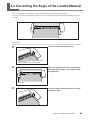
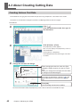
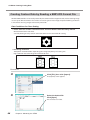
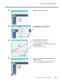
1
USER'S MANUAL Thank you very much for purchasing this product. To ensure correct and safe usage with a full understanding of this product's performance, please be sure to read through this manual completely and store it in a safe location. Unauthorized copying or transferral, in whole or in part, of this manual is prohibited. The contents of this operation manual and the specifications of this product are subject to change without notice. The operation manual and the product have been prepared and tested as much as possible. If you find any misprint or error, please inform us. Roland DG Corp. assumes no responsibility for any direct or indirect loss or damage which may occur through use of this product, regardless of any failure to perform on the part of this product. Roland DG Corp. assumes no responsibility for any direct or indirect loss or damage which may occur with respect to any article made using this product. For the USA FEDERAL COMMUNICATIONS COMMISSION RADIO FREQUENCY INTERFERENCE STATEMENT This equipment has been tested and found to comply with the limits for a Class A digital device, pursuant to Part 15 of the FCC Rules. These limits are designed to provide reasonable protection against harmful interference when the equipment is operated in a commercial environment. This equipment generates, uses, and can radiate radio frequency energy and, if not installed and used in accordance with the instruction manual, may cause harmful interference to radio communications. Operation of this equipment in a residential area is likely to cause harmful interference in which case the user will be required to correct the interference at his own expense. For Canada NOTICE This Class A digital apparatus meets all requirements of the Canadian Interference-Causing Equipment Regulations. AVIS Cet appareil numerique de la classe A respecte toutes les exigences du Reglement sur le materiel brouileur du Canada. For California WARNING This product contains chemicals known to cause cancer, birth defects and other reproductive harm, including lead. Unauthorized changes or modification to this system can void the users authority to operate this equipment. Use only I/O cables that have been designed and manufactured specifically for this device. For EU Countries Manufacturer: ROLAND DG CORPORATION 1-6-4 Shinmiyakoda, Kita-ku, Hamamatsu-shi, Shizuoka-ken, 431-2103 JAPAN The authorized representative in the EU: Roland DG EMEA, S.L. Parc Tecnologic del Valles C/ Ceramistes, 6 08290 Cerdanyola del Valles / Barcelona Spain For EU Countries WARNING This is a Class A product. In a domestic environment this product may cause radio interference in which case the user may be required to take adequate measures. Roland DG Corp. has licensed the MMP technology from the TPL Group. Contents Contents.........................................................................................................1 Read This First...............................................................................................3 Machine Functions............................................................................................................................ 3 To Ensure Safe Use..................................................................................6 Important Notes on Handling and Use.........................................................10 Chapter 1: Setup Preparation............................................................................ 11 1-1 Included Items........................................................................................12 1-2 Part Names............................................................................................13 Main Unit............................................................................................................................................13 1-3 Installing.................................................................................................14 Deciding On an Installation Site................................................................................................14 Installation Space............................................................................................................................14 Removing the Packing Materials...............................................................................................15 Connecting the Cables..................................................................................................................16 Chapter 2: Installing Software...........................................................................17 2-1 About the Included Software..................................................................18 2-2 If You're Using a Windows.....................................................................19 System Requirements....................................................................................................................19 One-operation Installation of Driver and Software............................................................20 2-3 If You're Using a Macintosh....................................................................23 System Requirements....................................................................................................................23 Installing the Software..................................................................................................................23 Chapter 3: Performing Cutting..........................................................................25 3-1 What to Know Before Cutting.................................................................26 Useable Material Types..................................................................................................................26 3-2 Cutting....................................................................................................27 Step 1: Load Material......................................................................................................................27 Step 2: Create Cutting Data.........................................................................................................30 Step 3: Perform Cutting.................................................................................................................34 Step 4: Apply the Cut Material....................................................................................................36 Chapter 4: Mastering the STIKA........................................................................37 4-1 Optimizing the Cutting Quality for the Material................................................... 38 Check the Cutting Quality for the Material............................................................................38 Adjusting the Blade Extension Amount..................................................................................39 4-2 Correcting the Angle of the Loaded Material............................................... 41 4-3 About Creating Cutting Data..................................................................42 Creating Various Text Data...........................................................................................................42 Creating Contour Data by Reading a BMP/JPG Format File.............................................44 Deleting Undesired Cutting Lines.............................................................................................46 4-4 Applying Large Materials........................................................................47 1 Contents Chapter 5: Maintenance.....................................................................................49 5-1 Maintenance..........................................................................................50 Cleaning the Blade Tip...................................................................................................................50 Cleaning the Blade Holder...........................................................................................................50 Cleaning the Main Unit.................................................................................................................50 5-2 Replacing Consumables........................................................................51 Replacing the Blade........................................................................................................................51 Replacing the Blade Protector....................................................................................................52 Chapter 6: Appendix...........................................................................................55 6-1 What to Do If..........................................................................................56 The machine does not run properly.........................................................................................56 The cut incisions are not clean...................................................................................................56 Parts of the material are not continuously cut.......................................................................56 The cut location is shifted forward/back................................................................................56 The cut location is shifted left/right.........................................................................................57 The material shifts during cutting.............................................................................................57 Installing the driver separately...................................................................................................57 Installing software and electronic manual separately.......................................................59 If the driver cannot be installed.................................................................................................59 Uninstalling the driver...................................................................................................................60 6-2 Shaft Lubrication....................................................................................62 6-3 Cutting Range........................................................................................63 6-4 Locations of the Power Rating and Serial Number Labels.......................... 64 6-5 Specifications.........................................................................................65 System Requirements for USB Connection............................................................................65 CutStudio is a trademark of Roland DG Corp. Windows® is either a registered trademark or trademark of Microsoft® Corporation in the United States and/or other countries. Macintosh and Mac OS are registered trademarks or trademarks of Apple Computer, Inc. in the USA and other countries. Adobe and Adobe Illustrator are either registered trademarks or trademarks of Adobe Systems Incorporated in the United States and/or other countries. Corel and CorelDRAW are registered trademarks or trademarks of Corel Corporation or Corel Corporation Limited. Other company names and product names are trademarks or registered trademarks of their respective holders. Copyright© 2005-2013 Roland DG Corporation 2 http://www.rolanddg.com/ Read This First Machine Functions For Windows You can use the included cutting software "Roland CutStudio" to create stickers and stickers with images. CutStudio Overview, Installation Method User's Manual (this document) p 18 You can use your own designs to create original stickers. User’s Manual (this document) p 27 CutStudio STIKA Sticker You can use STIKA in combination with a printer to create stickers with images. Windows Advanced Guide (electronic format) CutStudio Printer STIKA Sticker with image 3 Read This First You can use the included Adobe Illustrator software plug-in "CutStudio Plug-in for Adobe Illustrator" to send cutting data created in Illustrator to CutStudio and create stickers and stickers with images. Software plug-in overview, installation method Windows Advanced Guide (electronic format) You can make stickers with data created in Illustrator. Windows Advanced Guide (electronic format) Illustrator + CutStudio STIKA Sticker You can use STIKA in combination with a printer to create stickers with images. Windows Advanced Guide (electronic format) Illustrator + CutStudio STIKA Printer Sticker with image You can use the included CorelDRAW software plug-in "CutStudio Plug-in for CorelDRAW" to send data created in CorelDRAW to CutStudio and create stickers. Software plug-in overview, installation method Windows Advanced Guide (electronic format) You can create stickers with data created in CorelDRAW. Windows Advanced Guide (electronic format) CorelDRAW + CutStudio 4 STIKA Sticker Read This First You can use the included software "STIKA Navi" to operate STIKA from your computer. Operation is simple; just follow the instructions displayed on your computer screen. STIKA Navi Overview Windows Advanced Guide (electronic format) You can run a material jam test. Windows Advanced Guide (electronic format) STIKA Navi Operation Screen Click STIKA You can cut in areas of the material that have not yet been cut. Windows Advanced Guide (electronic format) STIKA Navi Operation Screen Click STIKA Unused part For Macintosh You can use the included software plug-in "CutStudio Plug-in for Adobe Illustrator" to make stickers with data created in Illustrator. Software plug-in overview, installation method User's Manual (this document) p 23 You can create stickers with data created in Illustrator. Macintosh Cutting Guide (electronic format) Illustrator + CutStudio STIKA Sticker 5 To Ensure Safe Use Improper handling or operation of this machine may result in injury or damage to property. Points which must be observed to prevent such injury or damage are described as follows. About WARNING and WARNING CAUTION Notices Used for instructions intended to alert the user to the risk of death or severe injury should the unit be used improperly. Used for instructions intended to alert the user to the risk of injury or material CAUTION damage should the unit be used improperly. * Material damage refers to damage or other adverse effects caused with respect to the home and all its furnishings, as well to domestic animals or pets. About the Symbols The symbol alerts the user to important instructions or warnings. The specific meaning of the symbol is determined by the design contained within the triangle. The symbol at left means "danger of electrocution." The symbol alerts the user to items that must never be carried out (are forbidden). The specific thing that must not be done is indicated by the design contained within the circle. The symbol at left means the unit must never be disassembled. The symbol alerts the user to things that must be carried out. The specific thing that must be done is indicated by the design contained within the circle. The symbol at left means the power-cord plug must be unplugged from the outlet. 6 To Ensure Safe Use Incorrect operation may cause injury WARNING Keep children away from the machine. The machine includes areas and components that pose a hazard to children and may result in injury, blindness, choking, or other serious accident. Never attempt to disassemble, repair, or modify the machine. Doing so may result in fire, electrical shock, or injury. Entrust repairs to a trained service technician. For accessories (optional and consumable items, AC adapter, power cord, and the like), use only genuine articles compatible with this machine. Incompatible items may lead to an accident. CAUTION Caution: cutting tool. This machine has an internal tool. To avoid injury, handle the tool with care. Before attempting cleaning, maintenance, or attachment or detachment of optional items, disconnect the power cord. Attempting such operations while the machine is connected to a power source may result in injury or electrical shock. Never use the machine for any purpose for which it is not intended, or use the machine in an undue manner that exceeds its capacity. Doing so may result in injury or fire. Install in a location that is level and stable. Installation in an unsuitable location may cause an accident, including a fall or tipover. 7 To Ensure Safe Use Danger of electrical short, shock, electrocution, or fire WARNING Connect to an electrical outlet that complies with this machine's ratings (for voltage, frequency, and current). Incorrect voltage or insufficient current may cause fire or electrical shock. Ratings Never use out of doors or in any location where exposure to water or high humidity may occur. Never touch with wet hands. Doing so may result in fire or electrical shock. Never allow any foreign object to get inside. Never expose to liquid spills. Inserting objects such as coins or matches or allowing beverages to be spilled into the ventilation ports may result in fire or electrical shock. If anything gets inside, immediately disconnect the power cord and contact your authorized Roland DG Corp. dealer. Never place any flammable object nearby. Never use a combustible aerosol spray nearby. Never use in any location where gases can accumulate. Combustion or explosion may be a danger. 8 WARNING Handle the power cord, plug, and electrical outlet correctly and with care. Never use any article that is damaged. Using a damaged article may result in fire or electrical shock. When using an extension cord or power strip, use one that adequately satisfies the machine's ratings (for voltage, frequency, and current). Use of multiple electrical loads on a single electrical outlet or of a lengthy extension cord may cause fire. When the machine will be out of use for a prolonged period, disconnect the power cord. This can prevent accidents in the event of current leakage or unintended startup. Position so that the power plug is within immediate reach at all times. This is to enable quick disconnection of the power plug in the event of an emergency. Install the machine next to an electrical outlet. Also, provide enough empty space to allow immediate access to the electrical outlet. If sparking, smoke, burning odor, unusual sound, or abnormal operation occurs, immediately unplug the power cord. Never use if any component is damaged. Continuing to use the machine may result in fire, electrical shock, or injury. Contact your authorized Roland DG Corp. dealer. Do not use the supplied power cord and AC adapter with any other product. To Ensure Safe Use Important notes about the power cord, plug, and electrical outlet Never place any object on top or subject to damage. Never allow to get wet. Never bend or twist with undue force. Never make hot. Never pull with undue force. Dust may cause fire. Never bundle, bind, or roll up. 9 Important Notes on Handling and Use This machine is a precision device. To ensure the full performance of this machine, be sure to observe the following important points. Failure to observe these may not only result in loss of performance, but may also cause malfunction or breakdown. Main Unit This Machine Is a Precision Device Handle carefully, and never subject the machine to impact or excessive force. Install in a Suitable Location Install in a location having the specified temperature and relative humidity. Install in a stable location offering good operating conditions. Important Notes on Connecting the Cables Connect the power cord and the computer's input and output cables securely. When Moving the Machine When moving the machine, be sure to support the machine at its bottom, using both hands. Attempting to move the machine by holding it at a different location may damage the machine. 10 Chapter 1: Setup Preparation 11 1-1 Included Items The following items are packed together with the unit. Make sure they are all present and accounted for. AC adapter: 1 Power cord: 1 USB cable: 1 Replaceable blade protector: 1 * The shape depends on the model. Blade: 1 Blade holder: 1 Pin: 1 Test-use material (Colored material) :1 Test-use application tape (Transparent tape) :1 *The blade, blade holder and pin are installed onto the machine. CD-ROM: 1 12 User's Manual: 1 Chapter 1: Setup Preparation 1-2 Part Names Main Unit Blade protector Cutting carriage Blade holder Shaft cover Pinch rollers AC adapter jack * Sheet adjustment lever USB connector Power button Power light * The SV-15 has sheet adjustment levers on the left and right. The SV-12/8 has a sheet adjustment lever only on the right. Sheet feed knob Chapter 1: Setup Preparation 13 1-3 Installing Deciding On an Installation Site Install in a stable location offering good operating conditions. An unsuitable location can cause accident, faulty operation, or breakdown. WARNING Never use out of doors or in any location where exposure to water or high humidity may occur. Never touch with wet hands. Doing so may result in fire or electrical shock. WARNING Never place any flammable object nearby. Never use a combustible aerosol spray nearby. Never use in any location where gases can accumulate. Combustion or explosion may be a danger. WARNING Position so that the power plug is within immediate reach at all times. This is to enable quick disconnection of the power plug in the event of an emergency. Install the machine next to an electrical outlet. Also, provide enough empty space to allow immediate access to the electrical outlet. CAUTION Install in a location that is level and stable. Installation in an unsuitable location may cause an accident, including a fall or tipover. Unsuitable Installation Sites Locations subject to shaking or vibration Locations where the floor is tilted, not level, or unstable Dusty locations Locations exposed to considerable electrical or magnetic noise, or other forms of electromagnetic energy Locations with poor heat radiation Installation Space The material moves forward and backward during cutting. Do not place any objects in front of or behind the material. Make sure that there are no obstructions (such as a wall, etc.) behind the machine. Leave enough space so that no objects touch the sheet feed knob. 14 Chapter 1: Setup Preparation Leave enough space so that the power cord can always be reached. 1-3 Installing Removing the Packing Materials Tape and packing materials are attached to the machine to protect it from shocks during transportation. When installation is complete, remove these materials. Remove all packing materials. Any that remain may cause faulty operation or breakdown when the power is switched on. Packing materials Chapter 1: Setup Preparation 15 1-3 Installing Connecting the Cables WARNING Connect to an electrical outlet that complies with this machine's ratings (for voltage, frequency, and current). Incorrect voltage or insufficient current may cause fire or electrical shock. WARNING Handle the power cord, plug, and electrical outlet correctly and with care. Never use any article that is damaged. Using a damaged article may result in fire or electrical shock. WARNING When using an extension cord or power strip, use one that adequately satisfies the machine's ratings (for voltage, frequency, and current). Use of multiple electrical loads on a single electrical outlet or of a lengthy extension cord may cause fire. WARNING Use only brand-name AC adapters and power cords compatible with this machine. The use of an incompatible product could lead to an accident. DO NOT connect a USB cable at this point. Power cord AC adapter AC adapter Jack USB cable Power rating Electrical outlet You make the connection to the computer using the included USB cable. Connect the USB cable at the time indicated in the driver installation procedures. Driver installation may fail and the machine may become unusable if you connect a USB cable before starting installing the driver. p 20 "One-operation Installation of Driver and Software" Important Notes on USB Connection Never use a USB hub or the like. 16 Chapter 1: Setup Preparation Chapter 2: Installing Software This section describes how to install the included software. 17 2-1 About the Included Software The included CD-ROM contains the following software. Software for Windows STIKA Driver This is a Windows-based driver required for sending data from a computer to the machine. Be sure to install it. STIKA Navi This is software that lets you operate the machine from Windows. It can be used to move the blade and test the material feed. It is automatically installed when the STIKA driver is installed. Roland CutStudio Roland CutStudio is software that allows you to create cutting data and easily perform cutting operations. CutStudio Plug-in for Adobe Illustrator This is an Illustrator software plug-in that lets you cut from data created in Adobe Illustrator. CutStudio Plug-in for CorelDRAW This is a CorelDRAW software plug-in that lets you cut from data created in CorelDRAW. Software for Macintosh CutStudio Plug-in for Adobe Illustrator This is an Illustrator software plug-in that lets you cut from data created in Adobe Illustrator. 18 Chapter 2: Installing Software 2-2 If You're Using a Windows System Requirements Operating Systems Processor Drive Monitor Memory (RAM) Free hard-disk space required for installation Windows XP/Vista/7/8 (32 bit / 64 bit edition) The minimum required CPU for the operating system CD-ROM drive Windows-compatible monitor capable of displaying of 16 bit color (High Color) or more The minimum amount of required RAM for the operating system (1GB or more recommended) 10 MB Chapter 2: Installing Software 19 2-2 If You're Using a Windows One-operation Installation of Driver and Software You can install all software and driver at a time. Make sure to connect the machine and the computer following the procedures. To follow wrong procedure may make installation impossible. 1. One-operation Installation of Driver and Software. Before installation, confirm that the machine and the computer are not connected with the USB cable. Log on to Windows as “Administrators.” Insert the Roland Software Package CD-ROM into the computer. When the automatic playback window appears, click [Run menu.exe]. The [User Account Control] appears, click [Allow], and install the software. The setup menu appears automatically. Click [Install]. Select [Install], [Model Name] to install, port [USB], and click [Start]. Driver installation starts. Follow the messages to install the software. 20 Chapter 2: Installing Software 2-2 If You're Using a Windows The screen shown here is displayed, click [Install]. Windows 8 When the screen shown here is displayed, click [Install]. Windows Vista / 7 Click [Install this driver software anyway]. Windows XP Click [Continue Anyway]. When the screen shown here is displayed, click [finish]. Install the other software successively. Guidance for individual software is displayed automatically. Install the software following the guidance. When installation finishes, click setup menu. of the Remove the Roland Software Package from the CD-ROM drive. Chapter 2: Installing Software 21 2-2 If You're Using a Windows 2. Connect the machine and the computer with a USB cable. Switch the machine on. Connect the machine and the computer with a USB cable. Please use the included USB cable. Do not use a USB hub. Windows Vista / 7 / 8 The driver will be installed automatically. Windows XP If the screen is displayed, select [No, not this time] and click [Next]. Select [Install the software automatically] and click [Next]. Click [Finish]. If the following screen is displayed during installation Eject and remove the CD-ROM, and then click [Back] and repeat from the last screen. 22 Chapter 2: Installing Software Click [Continue Anyway]. 2-3 If You're Using a Macintosh System Requirements Your Macintosh must fulfill the following requirements in order to use STIKA for cutting operations. The Macintosh is Intel Mac. Illustrator CS3/4/5/6 operates on it. Installing the Software The included CD-ROM contains the "Mac OS Installation and Setup Guide," which explains how to install and set up the software and Macintosh Cutting Guide. If you’re using a Macintosh, follow the steps below to display the file, then follow the explanation to perform installation and setup. Procedure Insert the included CD-ROM into the CD-ROM drive. Thereafter, follow the instructions in the [Mac OS Installation and Setup Guide] to install and set up the software and Macintosh Cutting Guide. Double-click the [Roland SV Series] icon that appears on the desktop. Double-click the "Install_e.html" icon. The [Mac OS Installation and Setup Guide] appears. Chapter 2: Installing Software 23 24 Chapter 3: Performing Cutting This describes basic cutting operations under Windows. For other operations not covered in this chapter, refer to the "Windows Advanced Guide" (electronic format). 25 3-1 What to Know Before Cutting Useable Material Types The following materials can be used with this machine. Size Material Types (*) SV-15 SV-12 SV-8 Width: 360 to 381 mm Width: 280 to 305 mm Width: 200 to 215 mm (14-1/8 to 15 in.) (11 to 12 in.) (7-13/16 to 8-7/16 in.) 280 to 305 mm (11 to 12 in.) (A4 length) (A3 length, A4 width) (A3 length, A4 width) Length: 1100 mm Length: 1100 mm Length: 1100 mm (43-1/4 in.) or less (43-1/4 in.) or less (43-1/4 in.) or less Vinyl chloride material (material section thickness is 0.1 mm or less, thickness including the backing paper is 0.3 mm (0.012 in.) or less) Label paper (Thickness including backing paper is 0.3 mm (0.012 in.) or less) * The machine may not cut certain materials. Do not use material that is in a condition indicated below. It may come loose or jam during cutting. The material is curled upward. The material edge is not straight The left and right edges of the material aren't parallel The material is longer than 1100 mm (43-1/4 in.) Using Roll Material If you're using a roll of material, make sure to add a margin greater than 40 mm (1-5/8 in.) to the cutting area prior to cutting the material from the roll. Material with a maximum length of 1100 mm (43-1/4 in.) can be loaded into the machine. However, the cutting area is only 1000 mm (39-5/16 in.). Up to 1100 mm (43-1/4 in.) Cut the material at a right angle. If the front edge of the material is uneven, it may feed improperly during cutting and could skew diagonally and come loose. 26 Chapter 3: Performing Cutting 3-2 Cutting Let's look at the basic cutting method while creating the sticker indicated to the right. Follow the operations in the order indicated below. Step 1: Load Material Procedure Turn the machine off. Verify that the material is narrow enough to be loaded and that it touches the pinch rollers. Pinch rollers If you are using the SV-15 model, adjust the pinch rollers to the material width and then advance the material to touch the pinch rollers. p 28 "Changing Loadable Material Width (for SV-15)" Make the material edges even Verify that the left edge of the material is parallel with the guide line. * If it is not, trim the excess material from the edge of the material that is touching the pinch rollers until the left edge is parallel with the guide line. Guide line Turn the sheet feed knob and move the material into the machine and then back out. Verify that the material does not come loose. Sheet feed knob * Reload the material if it becomes skewed or if it comes loose. Align the material edge with the marks at the back of the blade protector. Chapter 3: Performing Cutting 27 3-2 Cutting Loading the Included Test-use Material The direction to load the included test-use material differs depending on the machine model. SV-15/12 ··· Sideways (Landscape) SV-8 ··· Lengthwise (Portrait) If you are using the SV-15 model, change the loadable material width to 280 to 305 mm (11 to 12 in.). p 28 "Changing Loadable Material Width (for SV-15)" Changing Loadable Material Width (for SV-15) In the SV-15 model, you can change the loadable material width to match the material being loaded (360 to 381 mm (14-1/8 to 15 in.) or 280 to 305 mm (11 to 12 in.)). Change the pinch roller location and driver settings to change the width. Raise the sheet adjustment lever on the right side. Sheet adjustment lever (right) Remove the pinch-roller stopper. Do not use excessive force to widen the opening when removing the pinch-roller stopper. If the opening is widened, the stopper may become loose and fall out when it is next attached to the unit. Pinch-roller stopper Move the right side pinch roller to match the width of the material being loaded and attach the pinch-roller stopper. Pinch roller Pinch roller For 280 to 305 mm (11 to 12 in.) 28 Chapter 3: Performing Cutting For 360 to 381 mm (14-1/8 to 15 in.) 3-2 Cutting Lower the sheet adjustment lever on the right side. Sheet adjustment lever (right) Load material. p 27 "Step 1: Load Material" For 280 to 305 mm (11 to 12 in.) For 360 to 381 mm (14-1/8 to 15 in.) Change the driver cutting area to match the size of the loaded material. Procedures 1 and 2 on page 30 "Step 2: Create Cutting Data" Chapter 3: Performing Cutting 29 3-2 Cutting Step 2: Create Cutting Data Use the cutting software "CutStudio" to create cutting data. Refer to "Roland CutStudio Online Help" for a detailed explanation of CutStudio operations and features. Log on to Windows as "Administrator" right. 1. Start CutStudio. Windows 8 Right-click the background in the [Start] screen to display the app bar, and click [All Apps]. Click [CutStudio]. Windows XP / Vista / 7 From the [Start] menu ( 2. ), click [All Programs] (or [Program]), then [CutStudio]. Make the settings for the cutting range. Click [File], then click [Cutting Setup]. The [Cutting Setup] screen appears. 30 Chapter 3: Performing Cutting Select the name of the model you are using under [Name]. Click [Properties]. The [Properties] screen appears. 3-2 Cutting Click the [Size] tab. Set the cutting range to match the loaded material size. For the width, click [ ] to select either 250 (9.84 in.) or 340 mm (13.39 in.) (SV-15 only). (* Set to 250 mm (9.84 in.) if you are using the included test-use material.) The width cannot be changed on the SV-12/8 models. For the length, set a range that subtracts the margin from the loaded material length. p 63 "Cutting Range" Click [OK]. Click [OK] again to close the [Cutting Setup] screen. The cutting range has now been set. The white area is the cutting range. Text or shapes drawn outside this range are not cut. Chapter 3: Performing Cutting 31 3-2 Cutting 3. Insert text and shapes to create the cutting data. In this example, we'll enter the word "SALE" as the text and draw a frame around it to make it easier to peel off later. Click [ Click anywhere in the white area, then type in "SALE." Click [ ]. ]. Displayed around the text are and symbols. Drag the and symbols for the text box to change the size of the text. Click, then drag to change to the required size. 32 Click the upper-left corner, then drag to the lower right to change to the required size. Chapter 3: Performing Cutting Click [ ]. Draw a rectangle around the "SALE" text. 3-2 Cutting Click [ ]. Use the mouse to select an area containing the text and the rectangle. When you select this, the line turns blue. Move the position to the top of the window, near the origin point. Origin point Move the pointer to inside the text. When the shape of the pointer changes to a cross, drag to move. Click [Save]. For "Save in," choose the folder you want. Enter the file name, then click [Save]. The [Save As] screen appears. The data you created is saved. Important Note When Saving Data The cutting range set in [File] – [Cutting Setup] – [Properties] is not saved. The next time you import data, go to the [Cutting Setup] menu and redo the setting for the cutting range. Chapter 3: Performing Cutting 33 3-2 Cutting Step 3: Perform Cutting Before cutting, verify that Step 1: "Load Material" and Step 2: "Create Cutting Data" preparation have been completed. Procedure Press the power button and turn the machine on. The power light flashes. The cutting carriage moves to the left edge of the machine. Once the light changes to a steady illumination, the machine is ready to cut. Click [Cutting]. Click [OK]. The cutting data is sent from the computer and cutting starts. Cutting of the "SALE" text and the box ends. 34 Chapter 3: Performing Cutting 3-2 Cutting Press the power button and turn power off. Verify that the power light extinguishes. Turn the sheet feed knob and remove the material. To Stop Cutting While in Progress Press the power button and turn the machine off. Press the power button again and turn the machine on. The cutting carriage returns to the left edge. If you need to cut the material again, first remove and then reload it. You can also cancel a cutting operation from STIKA Navi. For more information, refer to the "Windows Advanced Guide" (electronic format). Chapter 3: Performing Cutting 35 3-2 Cutting Step 4: Apply the Cut Material Use application tape to affix the cut material. Cut the application tape to the required size for use. Before applying, thoroughly clean the surface where you want to affix the material to remove any dust or grease. Procedure Remove the excess tape so that only text remains. Use a commercially-available tweezers to remove small pieces of tape better. Application tape Cut the application tape to the required size. Cover the cut material flush with the application tape to prevent any air from getting underneath, then transfer the material. You can transfer the material easily by using a commercially available squeegee or the flat part of a ruler or the like to rub the cut material from above the application tape. Affix the material together with the joined application tape to the target object, then press down on it from above. Make sure the material is affixed to the object, then slowly peel off the application tape. If air becomes trapped between the material and the application surface, forming an air bubble, then use a needle to pop the bubble and press out the air to form a complete seal. This completes the procedure for attaching the material. Material After Cutting Transfer the cut material to the application tape and affix it to the object as soon as possible. Any dust that builds up on the surface of the material can make it difficult for the application tape to stick. 36 Chapter 3: Performing Cutting Chapter 4: Mastering the STIKA This describes in details how to adjust the blade extension amount, how to correct the angle of the loaded material, and how to create cutting data. 37 4-1 Optimizing the Cutting Quality for the Material Check the Cutting Quality for the Material Perform a cutting test to check the cutting quality for the material. Perform a cutting test when changing the material type and when adjusting the blade extension. Make sure to load material before performing a cutting test. Failure to do so could damage the blade and blade protector. Do not move the cutting carriage with your hand. Doing so could damage the machine. Do not touch any moving parts while the machine is operating. Doing so could cause a malfunction. Procedure Load the material. With the power light on, hold down the power button for 2 seconds or longer. 2 seconds or longer Remove your finger once the cutting carriage starts to move. Cutting begins from the location that the blade is currently located and the shape indicated in the figure is cut. To consecutively perform cutting tests, hold down the power button for 2 seconds or longer once the prior cutting operation has finished. This cutting test is done in an area that doesn't overlap with the previous cutting location. Peel off the cut shapes and check the cutting quality for the material. The material cutting quality is controlled by the blade extension amount. Adjust the blade extension amount depending upon the state of the material when it is peeled off. p 39 "Adjusting the Blade Extension Amount" The cross-shaped blade leaves faint traces on the material's backing paper This is the optimal blade extension amount. No adjustment is required. Optimal blade extension amount 38 Chapter 4: Mastering the STIKA 4-1 Optimizing the Cutting Quality for the Material The material is difficult to peel from the backing paper The blade trace is indistinct Cutting results shift Extend the blade. The blade extension is too short The blade cuts into the backing paper The blade cuts through the backing paper The material curls during cutting Retract the blade. The blade extension is too long Adjusting the Blade Extension Amount CAUTION Do not touch the tip of the blade with your fingers. Doing so may result in injury. Procedure Blade holder Turn the machine off. Loosen the screw, remove the blade holder. Screw Adjust the blade extension amount. 0.1 mm Turn the tip of the blade holder as indicated in the figure to extend the blade tip. Turn the large cap once to extend the blade tip by 0.1mm. The blade tip essentially cannot be seen from the blade holder. Chapter 4: Mastering the STIKA 39 4-1 Optimizing the Cutting Quality for the Material Support the screw from below and insert the blade holder. Tight contact Support the screw from below. Tighten the screw. Tug the blade holder upward to make sure it does not come loose. Screw Carry out the cutting test and check the cutting quality for the material. Repeat until optimal cutting quality is attained. p 38 "Check the Cutting Quality for the Material" Rough Estimate for the Amount of Blade Extension Use the following dimension as a rough estimate for setting the amount of blade extension. Amount of blade Thickness of the = + extension media portion Material portion Backing paper portion Holder Blade Thickness of the backing paper 2 Half of the backing paper Amount of blade is approximately equal to cutting-in amount * Suggested point The optimal setting has been achieved when there are faint lines on the backing paper when a cutting test is executed. 40 Chapter 4: Mastering the STIKA 4-2 Correcting the Angle of the Loaded Material If it is not loaded parallel into the machine, the material may come loose during cutting. You can use the sheet adjustment lever to correct the angle of the material without removing it from the machine. Procedure Raise the sheet adjustment lever. Sheet adjustment lever Move the material backward and forward and align the left edge of the material with the guide line. Guide line Lower the sheet adjustment lever to fix the material in place. Chapter 4: Mastering the STIKA 41 4-3 About Creating Cutting Data Creating Various Text Data The method for changing the size and font of input text using "Properties" is described in this section. CutStudio can use Windows TrueType-based fonts and OpenType fonts based on TrueType. Procedure Click [ ]. Click the desired area and, then type in the characters. Click [Format] – [Font]. The [Properties] screen appears. You can also display the [Properties] screen as indicated below. Click [Format] – [Properties]. Click [Properties] on the mouse right-click shortcut menu. Change the text size and design. When changing the text size, enter into [Text Height] the height at which you want to cut the text. When you change the text height, the text width is changed to the same degree. To change the text design, click the [ ] in the field underneath Font and select the desired font. Click [OK]. The font design and size are modified. For more information about the [Properties] screen, refer to "Roland CutStudio Online Help." 42 Chapter 4: Mastering the STIKA 4-3 About Creating Cutting Data Click [ ]. Draw a rectangle around the characters. Drawing a square around the text will make the material easier to peel off. When cutting small text, draw a square around each character. Drag. Click [Save]. For "Save in," choose the folder you want. Enter the file name, then click [Save]. The [Save As] screen appears. The data you created is saved. Chapter 4: Mastering the STIKA 43 4-3 About Creating Cutting Data Creating Contour Data by Reading a BMP/JPG Format File Windows BMP/JPG files can be read by CutStudio, the contours of the image detected, and the resulting image cut. It may be difficult to detect the contours of certain types of read images. Keep the following conditions in mind when selecting images to be read by CutStudio. Data Conditions for Clean Cutting Colors must not contain continuous tones and color borders must be clearly defined. We recommend black and white. Scanned photos generally contain continuous tones and are unsuitable for cutting. Increasing resolution The optimal resolution differs depending upon image complexity and cutting size. High-resolution data takes longer for CutStudio to read. Procedure Click [File], then click [Import]. Select the desired file. Click [Open]. The [Import] screen appears. The read data is laid out. 44 Chapter 4: Mastering the STIKA 4-3 About Creating Cutting Data Adjust the size and location. Click [Object] – [Image Outline]. Click [Extract Contour Lines]. The [Image Outline] screen appears. The image contour is detected. The contour displays as a blue line. Verify that the contour line is correct, and then click [OK]. The image contour is detected. You can use the object tool to reshape the image if needed. For more information about how to use the object tool, refer to "Roland CutStudio Online Help." Object tool Chapter 4: Mastering the STIKA 45 4-3 About Creating Cutting Data Deleting Undesired Cutting Lines CutStudio can be used to delete contour line that is not needed. Procedure Select the detected contour line. Click [Object] – [Break Polyline]. The image contour is separated. Click on the undesired cutting line. Click [Edit] – [Delete]. The undesired cutting line is deleted. The read data remains and is not deleted. Drag the mouse to select the remaining contour lines. To select all contour lines on the CutStudio screen, click [Edit] – [Select All]. Hold down the Shift key and click contour lines to select only those desired. 46 Click [Object] – [Integrate Polylines]. The separated contour line is made whole. Chapter 4: Mastering the STIKA 4-4 Applying Large Materials As the size of the material to be applied increases, it will become increasingly difficult to keep the entire material from slipping during application and to prevent air bubbles from becoming trapped between the material and application surface. Spray the application surface with detergent-containing water to allow you to move and place the material in the desired location, and to decrease the likelihood of bubbles becoming trapped between the application surface and material. Procedure Prepare the cut material and tape the material from the top with application tape. Remove any dust and grease from the application surface. Use a commercially available spray bottle to liberally spray the application surface with water containing 2 to 3 drops of a neutral detergent. Apply the material to the application surface. Adjust the material location and angle. Use a commercially available squeegee or the flat part of a ruler to remove all remaining moisture. Once all water has evaporated, slowly peel off the application tape. Chapter 4: Mastering the STIKA 47 48 Chapter 5: Maintenance This describes how to clean the machine and replace the blade. 49 5-1 Maintenance When cleaning, unplug the machine's power cord and remove all material. Cleaning the Blade Tip CAUTION Do not touch the tip of the blade with your fingers. Doing so may result in injury. Dust and material adhesive can collect on the tip of the blade and degrade cutting performance. Remove any dust or material adhesive adhering to the blade tip. Cleaning the Blade Holder CAUTION Do not touch the tip of the blade with your fingers. Doing so may result in injury. Dust and adhesive material can collect within the blade holder and degrade cutting performance. Take off the tip of the blade holder and remove any pieces of material inside. Turn the tip of the blade holder as indicated in the figure to remove. Cleaning the Main Unit Use a dry cloth to gently wipe any dirt from the main unit. Never use a solvent such as thinner or benzene. 50 Chapter 5: Maintenance 5-2 Replacing Consumables Replacing the Blade If you adjust the blade amount and implement a cutting test several times, and the machine still does not properly cut the material, the blade tip may be worn or damaged. Replace with a new blade. Before replacing the blade, remove the material. CAUTION Do not touch the tip of the blade with your fingers. Doing so may result in injury. Procedure Unplug the power cord from the machine. Blade holder Loosen the screw, remove the blade holder. Screw Press the pin and remove the old blade. Pin Old blade Press the new blade in until you hear an audible click. Blade Support the screw from below and insert the blade holder. Tight contact Support the screw from below. Chapter 5: Maintenance 51 5-2 Replacing Consumables Blade holder Tighten the screw. Tug the blade holder upward to make sure it does not come loose. Screw Replacing the Blade Protector Even if the blade protector is slightly damaged, cutting operation will not be affected. If the blade protector is damaged to the extent that cutting quality is degraded, replace it with the included replacement blade protector. CAUTION The cutter knife used here is sharp and poses a hazard. Carry out operations with caution to avoid injury. Procedure Unplug the power cord from the machine. Peel the blade protector from the main unit. Use a commercially available retractable knife to facilitate removal. If you are using the SV-15, raise the left/right sheet adjustment levers and remove the blade protector. * Do not place your hands in front of the direction that you are moving the retractable knife. Wipe and remove any glue remaining on the main unit. Use a cloth to wipe clean. Place the replacement blade protector into the machine. Align the blade protector using the reference line displayed on the machine. Reference line 52 Chapter 5: Maintenance 5-2 Replacing Consumables Peel off the double-sided tape and affix the blade protector. For the SV-15, lower the left/right sheet adjustment levers. Sheet adjustment levers Chapter 5: Maintenance 53 54 Chapter 6: Appendix 55 6-1 What to Do If This section describes what to do if you encounter a problem while using the machine. Refer to this first, before assuming that a malfunction has occurred. The method for resolving problems not listed below are indicated in the "Windows Advanced Guide" or "Macintosh Cutting Guide" (electronic format). Use both as necessary. The machine does not run properly Is the cable properly connected? If the power cord or USB cable are not properly connected, refer to the following page and connect properly. p 16 "Connecting the Cables" Are the settings for the driver correct? Make sure the communication port is set correctly. Is the power lamp flashing? The problem is a communication or command error. Turn power off, verify the cable connection and computer/software settings. Power does not turn off even when the power button is pressed Unplug the AC adapter from the machine. The cut incisions are not clean Is the blade extension amount optimal? Check whether the blade extension amount has been adjusted. p 39 "Adjusting the Blade Extension Amount" Is the blade holder fixed in place? Firmly attach so that the screw does not loosen during cutting. Is the tip of the blade broken? Replace with a new blade. p 51 "Replacing the Blade" Parts of the material are not continuously cut Is the tip of the blade broken? Replace with a new blade. p 51 "Replacing the Blade" Is dust or material adhesive attached to the blade tip? Remove the blade and clean the tip. p 50 "Cleaning the Blade Tip" 56 Chapter 6: Appendix Is there a build-up of material adhesive or dust within the blade holder? Take off the tip of the blade holder and remove any pieces of material inside. p 50 "Cleaning the Blade Holder" Are there any scratches on the blade protector? If the blade protector is damaged, correct cutting of material may be impossible even if the machine's settings and the installation of the blade and blade holder are all correct. Replace with a new blade protector. p 52 "Replacing the Blade Protector" Is the blade holder damaged or worn? Replace with a new blade holder. The cut location is shifted forward/back Is the blade extension amount optimal? Check whether the blade extension amount has been adjusted. p 39 "Adjusting the Blade Extension Amount" Did the material come up against an obstruction while it was being cut? Do not place anything in front of or behind the machine. This can obstruct the material feed and cause the cut location to shift. 6-1 What to Do If The cut location is shifted left/right If the cut location shifts as indicated below, check the following. Are the material edges evenly cut? If the material edges are cut at an angle, trim the excess so that the material is even with the guidelines when loaded. Did the material come up against an obstruction while it was being cut? The spacing between characters differs Do not use material wider than can be handled. The left and right edges of the material will touch the inner surfaces of the machine and in addition to shifting the location, the material may also be damaged. Are you using material that has creases or folds? A location different than the data indicates is cut Is the blade extension amount optimal? Check whether the blade extension amount has been adjusted. p 39 "Adjusting the Blade Extension Amount" This may prevent the material from properly feeding and may shift the material position. Remove the creases or folds and reload the material. Installing the driver separately Log on to Windows as “Administrators.” Insert the Roland Software Package CD-ROM into the computer. When the automatic playback window appears, click [Run menu.exe]. The [User Account Control] appears, click [Allow], and install the software. The setup menu appears automatically. Does the cutting carriage move abnormally and do you hear a strange noise? Remove any dust or material adhesive adhering to cutting carriage guide shaft and then lubricate. p 62 "Shaft Lubrication" The material shifts during cutting p 60 "Uninstalling The Driver." Is the material length 500 mm (19-5/8 in.) or longer? If they are 500 mm (19-5/8 in.) or longer, certain types of material may shift during cutting. Either switch to a different kind of material, or shorten the material length. Uninstall the driver if it has been already installed. Go to Step if the driver is not installed or it is uninstalled. Click “Custom Install.” Is the material length too short? If too short, certain types of material with little rigidity may shift during cutting. Either switch with a different material or use a longer length of the same material. Chapter 6: Appendix 57 6-1 What to Do If Click [Install] of the "Windows Driver." Select [Install], [Model Name] to install, and port [USB], and click [Start]. Windows Vista / 7 If the screen shown here is displayed, click [Install this driver software anyway]. Windows XP Driver installation starts. Follow the onscreen instructions and continue with the installation. Click [Continue Anyway]. If the screen shown here is displayed, click [Install]. Windows 8 When the screen shown here is displayed, click [finish]. Click Remove the Roland Software Package from the CD-ROM drive. Connect according to p 22 Step 2. “Connect the machine and the computer with a USB cable.” of the setup menu. If the screen shown here is displayed, click [Install]. 58 Chapter 6: Appendix 6-1 What to Do If Installing software and electronic manual separately Log on to Windows as “Administrators.” Insert the Roland Software Package CD-ROM into the computer. When the automatic playback window appears, click [Run menu.exe]. The [User Account Control] appears, click [Allow], and install the software. The setup menu appears automatically. Click "Custom Install." Click [Install] of the program you want to install. If the driver cannot be installed If installation quits partway through, or if the wizard does not appear when you make the connection with a USB cable, take action as follows. Windows 8 1. Use a USB cable to connect the machine and the PC, and then turn the machine on. 2. If the [Found New Hardware] wizard appears, click [Cancel] to close it. Disconnect any USB cables for printers other than this machine. 3. Click [Desk top]. 4. Move the mouse to the lower right corner to display Charm and click [Set]. 5. Click [PC Information]. 6. Click [Device Manager]. When the [User Account Control] screen appears, click [Continue]. The [Device Manager] screen appears. 7. Click [Show hidden devices] on the View menu. 8. Double-click [Printers] or [Other devices] in the list. Click the model name or [Unknown device], whichever appears below the item you selected. 9. Click [Delete] on the [Action] menu. 10. In the [Confirm Device Uninstall] dialog box, click [OK] to close the [Device Manager]. 11. Disconnect the USB cable that is connected to the printer, and then restart Windows. 12. Uninstalling the driver. Follow p 60 "Uninstalling driver Windows 8" to uninstall the driver. 13. Follow p 57 "Installing the driver separately" to install the driver again. Windows 7/ Vista Follow the on-screen instructions and continue with the installation. When installation finishes, click of the setup menu. 1. Use a USB cable to connect the machine and the PC, and then turn the machine on. 2. If the [Found New Hardware] wizard appears, click [Cancel] to close it. Disconnect any USB cables for printers other than this machine. 3. On the taskbar, click [Start], and then right-click [Computer]. Click [Properties]. 4. Click [Device Manager]. When the [User Account Control] dialog box appears, click [Continue]. The [Device Manager] screen appears. Remove the Roland Software Package from the CD-ROM drive. 5. Click [Show hidden devices] on the [View] menu. 6. Double-click [Printers] or [Other devices] in the list. Click the model name or [Unknown device], whichever appears below the item you selected. 7. Click [Delete] on the [Action] menu. 8. In the [Confirm Device Uninstall] dialog box, select the "Delete the driver software for this device." Check box, and then click [OK] to close the [Device Manager]. Chapter 6: Appendix 59 6-1 What to Do If 9. Disconnect the USB cable that is connected to the printer, and then restart Windows. 10. Uninstalling the driver. Uninstall the driver following the instructions of p 60 "Uninstalling the driver Windows 7.” 11. Follow p 57 "Installing the driver separately" to install the driver again. Windows XP 1. If the [Found New Hardware Wizard] appears, click [Finish] to close it. 2. Display [System Properties]. 3. Click the [Hardware] tab, then click [Device Manager]. The [Device Manager] appears. 4. Delete the model name in use (or [Unknown Device]). At the [View] menu, click [Show hidden devices]. Go to the [Action] menu, and click [Uninstall]. Find [Printers] or [Other device], then double-click it. Click the model name in use (or [Unknown Device]). Uninstalling the driver Windows 8 1. Turn the machine off, and disconnect the cable that is connecting the PC and the machine. 2. Start Windows. 3. Click [Desk top]. 4. Move the mouse to the lower right corner to display Charm and click [Set]. 5. On the task bar, click [Control Panel], and then [Uninstall a program]. 6. Select the machine's driver that you want to uninstall, and then click [Uninstall]. 7. When a message prompting you to confirm that you want to uninstall the driver appears, click [Yes]. 8. On the task bar, click [Start], and then [Desk top]. 9. Start Windows Explorer to open the drive and folder where the driver is located. (* Notes) 10. Double-click the "SETUP64.EXE." or "SETUP.EXE." 11. When the [User Account Control] dialog box appears, click [Continue]. The driver's installer starts. 12. Click [Uninstall]. Select the machine that you want to uninstall, and then click [Start]. 13. When a dialog box prompting you to restart the PC appears, click [Yes]. 14. After the computer is restarted, display the Control Panel and click [View devices and printers]. 15. If the icon of the device you wish to remove is shown, right-click on the icon to click on [Remove device]. *When you are using the CD-ROM, specify one of the following folders. (The CD drive is drive D in this example). D:\Drivers\WIN8X64 (64-bit version) D:\Drivers\WIN8X86 (32-bit version) If you're not using the CD-ROM, go to the Roland DG Corp. website (http://www.rolanddg.com/), and download the driver for the machine you want to delete. Then, specify the folder where you extracted the downloaded file to. Windows 7 / Vista After the screen shown above appears, click [OK]. 5. Close the [Device Manager] and click [OK]. 6. Detach the USB cable connected to the computer. 7. Restart Windows, and refer to p 61 "Uninstalling the driver Windows XP" to uninstall the driver. 8. Follow p 57 "Installing the driver separately" to install the driver again. 60 Chapter 6: Appendix 1. Turn the machine off, and disconnect the USB cable that is connecting the PC and the machine. 2. Log on to Windows as an administrator. 3. On the task bar, click [Start], [Control Panel], and then [Uninstall a program]. 4. Select the machine's driver that you want to uninstall, and then click [Uninstall]. 5. When a message prompting you to confirm that you want to uninstall the driver appears, click [Yes]. 6. On the task bar, click [Start], [All Programs], [Accessories], [Run], and then [Browse]. 7. Choose the name of the drive or folder where the driver is located.* 8. Select "SETUP.EXE," click [Open], and then click [OK]. 9. When the [User Account Control] dialog box appears, click [Allow]. The driver's setup program starts. 6-1 What to Do If 10. Click [Uninstall]. Select the machine that you want to uninstall, and then click [Start]. 11. When a dialog box prompting you to restart the PC appears, click [Yes]. When the computer restarts, the uninstallation is finished. * When you are using the CD-ROM, specify one of the following folders. (The CD drive is drive D in this example). ( Windows 7) D:\Drivers\WIN7X64( 64-bit version ) D:\Drivers\WIN7X86( 32-bit version ) ( Windows Vista ) D:\Drivers\WINVISTAX64( 64-bit version ) D:\Drivers\WINVISTAX86( 32-bit version ) If you're not using the CD-ROM, go to the Roland DG Corp. website (http://www.rolanddg.com/), and download the driver for the machine you want to delete. Then, specify the folder where you extracted the downloaded file to. Windows XP 1. Turn the machine off, and disconnect the USB cable that is connecting the PC and the machine. 2. Log on to Windows as an administrator. 3. Insert the included CD-ROM into the CD-ROM drive. Go to the upper right and click the [X] to close the setup menu. 4. From the [Start] menu, click [Run]. 5. Type in the information shown below, then click [OK]. (CD-ROM drive letter ):\Drivers\WIN2KXP\SETUP.EXE The Setup program starts and the [Driver Setup] window appears. * In this illustration, drive D is specified as the CD-ROM drive. 6. Choose [Uninstall]. Select the model name you are using. Click [Start]. 7. Click [Yes] to restart the computer. Chapter 6: Appendix 61 6-2 Shaft Lubrication The material may not cut properly if dust and material adhesive adhere to the cutting carriage guide shaft. If the following symptoms are present, remove the shaft cover and lubricate the shaft located as indicated in the figure. Use a machine oil to lubricate. It does not move smoothly You hear an abnormal noise Procedure Unplug the power cord from the machine. Remove the shaft cover. Use a Phillips head screwdriver to remove the screws. Wipe and remove dust adhering to the shaft. Use machine oil to lightly lubricate the shaft section indicated in the figure to the left. Using too much oil can cause the material to stain. 62 Replace the shaft cover and screw into place. Chapter 6: Appendix 6-3 Cutting Range SV-15 SV-12 SV-8 Cutting Range (width) 340 mm (13-3/8 in.) Cutting Range (length) 1000 mm (39-5/16 in.) Loadable Material Width 360 to 381 mm (14-1/8 to 15 in.) Loadable Material Length 1100 mm (43-1/4 in.) 250 mm (9-13/16 in.) 250 mm (9-13/16 in.) 160 mm (6-1/4 in.) 1000 mm (39-5/16 in.) 1000 mm (39-5/16 in.) 1000 mm (39-5/16 in.) 280 to 305 mm (11 to 12 in.) 280 to 305 mm (11 to 12 in.) 200 to 215 mm (7-13/16 to 8-7/16 in.) 1100 mm (43-1/4 in.) 1100 mm (43-1/4 in.) 1100 mm (43-1/4 in.) The required margin to send the material forward/back is taken. When using the SV-15 When using the SV-12/8 Pinch rollers Pinch rollers Blade holder Margin 10 mm (3/8 in.) Maximum 1000 mm (39-5/16 in.) Blade holder Margin 10 mm (3/8 in.) Cutting range Maximum 1000 mm (39-5/16 in.) Cutting range Material Material Margin 30 mm (1-3/16 in.) Cutting range (width) 250 mm (9-13/16 in.) Loadable material width 280 to 305 mm (11 to 12 in.) Cutting range (width) 340 mm (13-3/8 in.) Loadable material width 360 to 381 mm (14-1/8 to 15 in.) Margin 30 mm (1-3/16 in.) Cutting range (length) SV-12: 250 mm (9-13/16 in.) SV-8 : 160 mm (6-1/4 in.) Loadable material width SV-12: 280 to 305 mm (11 to 12 in.) SV-8 : 200 to 215 mm (7-13/16 to 8-7/16 in.) Chapter 6: Appendix 63 6-4 Locations of the Power Rating and Serial Number Labels Serial number This is required when you seek maintenance, servicing, or support. Never peel off the label or let it get dirty. Power rating Use an electrical outlet that meets the requirements for voltage, frequency, and amperage given here. 64 Chapter 6: Appendix 6-5 Specifications SV-15 Cutting method Maximum cutting range Useable material size (*1) Maximum cutting speed Useable material type (*2) Interface Power supply Power consumption Dimensions Weight Acoustic noise level Operating environment Included items SV-12 Width: 340 mm (13-3/8 in.) Length: 1000 mm (39-5/16 in.) Width: 360 to 381 mm (14-1/8 to 15 in.) Length: 1100 mm (43-1/4 in.) or less SV-8 Media-moving method Width: 250 mm (9-13/16 in.) Length: 1000 mm (39-5/16 in.) Width: 280 to 305 mm (11 to 12 in.) (A3 length, A4 width) Length: 1100 mm (43-1/4 in.) or less Width: 160 mm (6-1/4 in.) Length: 1000 mm (39-5/16 in.) Width: 200 to 215 mm (7-13/16 to 8-7/16 in.) (A4 length) Length: 1100 mm (43-1/4 in.) or less 440 (W) × 205 (D) × 115 mm (H) (17-3/8 (W) × 8-1/8 (D) × 4-1/2 in. (H)) 2.7 Kg (6 lb) 340 (W) × 205 (D) × 115 mm (H) (13-3/8 (W) × 8-1/8 (D) × 4-1/2 in. (H)) 2.2 Kg (4.9 lb) Width: 280 to 305 mm (11 to 12 in.) (A3 length, A4 width) Length: 1100 mm (43-1/4 in.) or less 12 to 100 mm/sec. 12 to 40 mm/sec. 12 to 40 mm/sec. (7/16 to 3-7/8 in./sec.) (7/16 to 1-9/16 in./sec.) (7/16 to 1-9/16 in./sec.) Vinyl chloride material (material section thickness alone is 0.1 mm or less, thickness including backing paper is 0.3 mm (0.012 in.) or less) Label paper (Thickness including backing paper is 0.3 mm (0.012 in.) or less) USB 1.1 Dedicated AC adapter Input: AC 100 to 240 V ± 10%, 50/60 Hz Output: DC 19 V, 2.1 A Approx. 20 W (including AC adapter) 522 (W) × 205 (D) × 115 mm (H) (20-5/8 (W) × 8-1/8 (D) × 4-1/2 in. (H)) 3.3 Kg (7.3 lb) 60 dB (A) or less (according to ISO7779) Temperature: 5 to 40˚C (41 to 104˚F), humidity: 35 to 80% (no condensation) AC adapter, power cord, USB cable, replaceable blade protector, blade, blade holder, pin, test-use material, test-use application tape, CD-ROM, user's manual *1 Depending upon the type, material that is 500 mm (19-5/8 in.) or longer may shift during cutting. *2 You may also be unable to cut some types of material. System Requirements for USB Connection Computer USB cable Model preinstalled with the 32- or 64-bit edition of Windows XP, Vista, 7, 8 or upgraded computer originally preinstalled with Windows XP or later Use the included USB cable. Chapter 6: Appendix 65 For China 产品中有毒有害物质或元素的名称及含量 有毒有害物质或元素 部件名称 铅(Pb) 汞(Hg) 镉(Cd) 六价铬 (Cr(Ⅵ)) 多溴联苯 (PBB) 多溴二苯醚 (PBDE) 印刷电路板 × ○ × ○ ○ ○ 头部 × ○ ○ ○ ○ ○ 壳体、底架 × ○ ○ ○ ○ ○ 电源 × ○ × ○ ○ ○ 其他(电缆、附件等) × ○ ○ ○ ○ ○ ○:表示该有毒有害物质在该部件所有均质材料中的含量均在 GB/T26572-2011 标准规定的限量要求以下。 ×:表示该有毒有害物质至少在该部件的某一均质材料中的含量超出 GB/T26572-2011 标准规定的限量要求。 环保使用期限 此标志适用于在中国国内销售的电子信息产品,表示环保使用期限的年数。 所谓环保使用期限是指在自制造日起的规定期限内,产品中所含的有害物质 不致引起环境污染,不会对人身、财产造成严重的不良影响。 环保使用期限仅在遵照产品使用说明书,正确使用产品的条件下才有效。 不当的使用,将会导致有害物质泄漏的危险。 For EU Countries This product must be disposed of separately at your local waste recycling center. Do not dispose of in household waste bin. Lever dit product in bij een lokaal afvalverzamelpunt. NIET met normaal huishoudelijk afval afvoeren. Bitte führen Sie dieses Produkt separat Ihrer örtlichen Entsorgungsstelle zu. Bitte nicht mit dem normalen Hausmüll entsorgen. Dette Produkt skal smides særskilt væk på den lokale affalds- og genbrugsstation. Må ikke smides ud sammen med almindeligt husholdningsaffald. Ne jetez pas le produit avec vos ordures ménagères. Portez-le dans un centre recyclage des déchets. Tätä tuotetta ei saa hävittää normaalien talousjätteiden mukana, vaan se on toimitettava ongelmajätteiden keräilypisteeseen hävitettäväksi. Questo prodotto deve essere smaltito negli appositi contenitori per la raccolta differenziata, non buttare nel cestino dei rifiuti casalinghi. Produkten måste kasseras separat på din lokala återvinningscentral. Släng inte produkten tillsammans med hushållssoporna. Este producto debe devolverse al centro de reciclaje más cercano a su domicilio para su correcta eliminación. No lo tire a la basura. Μην πετάξετε το αντικείμενο αυτό στο καλάθι των απορριμμάτων. Αφαιρέστε τις μπαταρίες και προσκομίστε το στο τοπικό κέντρο ανακύκλωσης. Deite fora separadamente este produto no seu centro de reciclagem local. Não o deite fora no seu caixote do lixo. 66 67 68 Please read this Agreement before unpacking the media. Software license agreement Roland DG Corporation (hereinafter referred to as the “Company”) shall grant you a non-transferable, nonexclusive right to use the Software supplied with this Agreement, on the condition that you agree to the following provisions. If you agree to the following provisions, you should unpack the media on which the Software is recorded, or simply click the button or other indicator that you agree to the following provisions. By doing so, this Agreement shall be concluded. If you do not agree with the following provisions, do not unpack the media. Or, you can click the button or other indicator that you do not agree to the following provisions of this Agreement. In this case, a license is not granted and you cannot use the Software. 1. Definition The “Software” includes the software program and related files supplied with this Agreement and the related software programs and files distributed through the Internet and other services. 2. Ownership All the ownership, copyright and other intellectual property rights of the Software, trademark, and related documents shall belong to the Company. 3. Terms and conditions (1) You are authorized to use the Software on one computer. (2) You are allowed to create a backup copy of the Software. The right to keep the Software and the backup copy of the Software continues to belong to the Company, but the right to the media on which the backup copy of the Software is recorded does not belong to the Company. 4. Forbidden items (1) This copy of the Software, or a backup copy of the Software, must not be used on multiple computers at the same time, on a network, the Internet, or on other computers through any other means of distribution. (2) The Software shall not be reverse engineered, decompiled or reverse assembled. (3) The rights to the Software cannot be transferred, assigned, lent, loaned or licensed to a third party in any case, regardless of whether this Agreement has been terminated or cancelled. 5. Termination (1) The Company can cancel this Agreement and require you to discontinue use of the Software if you breach any provision of this Agreement or if you infringe on the ownership, copyright, or other intellectual property rights of the Company. (2) This Agreement shall be automatically terminated when you stop using the Software. (3) If this Agreement is terminated or cancelled, you must return your copy of the Software to the Company, or discard it as soon as practicable, at your own expense. 6. Guarantee (1) The Company shall not guarantee that the quality or functionality of the Software will satisfy any purpose that you may have in mind. (2) The Company shall not accept any responsibility for the results obtained from using the Software. (3) The Company shall not accept any responsibility for any loss which might be caused as a result of your exercising the rights granted under this Agreement. (4) The specifications for the Software are subject to change without prior notice. 7. Governing Law This Agreement shall be governed by the laws of Japan. R5-130823