1
User's Manual
1
Operation Screen
2
Milling
3
Maintenance
4
Troubleshooting
Roland DG Corporation has developed a special website introducing
dental solutions. For the latest information regarding this machine
(including manuals), see our special Easy Shape website (http://www.
rolandeasyshape.com).
Contents
Contents....................................................................................................................................... 2
1. Operation Screen............................................................................................................................ 4
Displaying or Exiting VPanel....................................................................................................... 5
What is VPanel?............................................................................................................................................................................... 5
Displaying VPanel.......................................................................................................................................................................... 5
VPanel Display in the Task Tray.................................................................................................................................................. 6
Exiting VPanel.................................................................................................................................................................................. 6
VPanel Window and Functions.................................................................................................... 7
Top Window...................................................................................................................................................................................... 7
"Settings" Tab................................................................................................................................................................................... 8
"Maintenance" Tab........................................................................................................................................................................ 9
"Mail" Tab........................................................................................................................................................................................10
"Manual correction" Dialog Box.............................................................................................................................................11
"Milling bur management" Dialog Box.................................................................................................................................12
"Milling bur registration" Dialog Box....................................................................................................................................13
"Cleaning tool" Dialog Box........................................................................................................................................................14
2. Milling............................................................................................................................................ 15
Using / Reading the Built-In Panel............................................................................................. 16
Using / Reading the Built-In Panel..........................................................................................................................................16
Statuses Indicated by Status Light Color.............................................................................................................................16
Switching the Power On or Off................................................................................................... 17
Switching the Power On...........................................................................................................................................................17
Switching the Power Off............................................................................................................................................................17
Preparing for Milling................................................................................................................... 18
Preparing a Workpiece (Usable Workpieces).....................................................................................................................18
Preparing a Milling Bur (Usable Milling Burs)....................................................................................................................18
Preparing Compressed Air (Setting the Regulator)........................................................................................................18
Starting Milling............................................................................................................................ 19
STEP 1: Mounting the Clamp to the Workpiece...............................................................................................................19
STEP 2: Attaching the Milling Bur..........................................................................................................................................23
STEP 3: Outputting Milling Data............................................................................................................................................24
Aborting Output...........................................................................................................................................................................26
Removing Milling Data in Standby from the Output List..............................................................................................26
3. Maintenance.................................................................................................................................. 27
Maintenance Precautions........................................................................................................... 28
Maintenance Precautions..........................................................................................................................................................28
Daily Maintenance ..................................................................................................................... 29
Cleaning after Milling Finishes...............................................................................................................................................29
Periodic Maintenance................................................................................................................. 31
Situations Requiring Maintenance........................................................................................................................................31
Replacing Consumable Parts..................................................................................................................................................31
Running In the Spindle (Warm-up)........................................................................................................................................32
Correcting the Milling Machine..............................................................................................................................................33
Care and Storage of Detection Pin and Automatic Correction Jig.............................................................................35
Retightening the Collet..............................................................................................................................................................36
Care of the Regulator.................................................................................................................................................................38
4. Troubleshooting............................................................................................................................ 40
Machine Trouble......................................................................................................................... 41
Initialization is Not Performed or Initialization Fails........................................................................................................41
The Operation Button Does Not Respond..........................................................................................................................41
VPanel Does Not Recognize the Machine...........................................................................................................................41
No Data is Being Output to the Machine, or the Machine will Not Operate Even Though Data is Being Output....42
The Computer Shuts Down when Connecting Multiple Machines...........................................................................42
2
The Spindle Does not Rotate....................................................................................................................................................42
The Ionizer is Ineffective (Milling Waste Collects Around the Milling Area)............................................................43
Compressed Air Does Not Come Out....................................................................................................................................43
Automatic Correction Fails........................................................................................................................................................43
The Milling Bur Management Information was Lost.......................................................................................................44
Milling Quality Problems............................................................................................................. 45
The Milled Surface is Not Attractive......................................................................................................................................45
There is a Line of Level Difference in the Milling Results...............................................................................................45
Chipping (Edges of Milling Products Become Chipped) Occurs.................................................................................45
A Hole Opens in the Milling Results......................................................................................................................................46
The Dimensions of the Milling Results Do Not Match....................................................................................................47
Installation Trouble.................................................................................................................... 48
Installing the Driver Separately..............................................................................................................................................48
Installing the Softwear and the Electronic Manual Separately...................................................................................50
Driver Installation Is Impossible.............................................................................................................................................51
Uninstalling the Driver..............................................................................................................................................................52
Uninstalling VPanel......................................................................................................................................................................53
Responding to Error Messages.................................................................................................. 54
Thank you very much for purchasing this product.
To ensure correct and safe usage with a full understanding of this product's performance, please be sure
to read through this manual completely and store it in a safe location.
Unauthorized copying or transferal, in whole or in part, of this manual is prohibited.
The contents of this operation manual and the specifications of this product are subject to change without
notice.
The operation manual and the product have been prepared and tested as much as possible. If you find any
misprint or error, please inform us.
Roland DG Corp. assumes no responsibility for any direct or indirect loss or damage which may occur through
use of this product, regardless of any failure to perform on the part of this product.
Roland DG Corp. assumes no responsibility for any direct or indirect loss or damage which may occur with
respect to any article made using this product.
http://www.rolanddg.com/
Company names and product names are trademarks or registered trademarks of their respective holders.
Copyright © 2015 Roland DG Corporation
Roland DG Corporation has licensed the MMP technology from the TPL Group.
3
1. Operation Screen
Displaying or Exiting VPanel......................................5
What is VPanel?...............................................................................5
Displaying VPanel............................................................................ 5
VPanel Display in the Task Tray....................................................... 6
Exiting VPanel..................................................................................6
VPanel Window and Functions...................................7
Top Window......................................................................................7
"Settings" Tab...................................................................................8
"Maintenance" Tab........................................................................... 9
"Mail" Tab.......................................................................................10
"Manual correction" Dialog Box..................................................... 11
"Milling bur management" Dialog Box............................................ 12
"Milling bur registration" Dialog Box............................................... 13
"Cleaning tool" Dialog Box.............................................................. 14
4
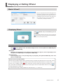
Displaying or Exiting VPanel
What is VPanel?
VPanel is an application that allows milling machine
operation on a computer screen. It has functions for
outputting milling data, performing maintenance,
and making various corrections. The milling machine status and errors can also be displayed.
"Setup Guide" ("Installing the Software")
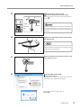
Displaying VPanel
Click
(VPanel icon) in the task tray on the
desktop.
The top window of VPanel will appear. If you cannot find
in the task tray, start the program from the Windows
[Start] screen (or the [Start] menu).
Starting from the Windows [Start] screen (or [Start] menu)
Windows 8.1
Click
on the [Start] screen, and from the Apps screen, click the [VPanel for DWX-51D] icon
under [Roland DWX-51D].
Windows 8
Right-click the background in the [Start] screen to display the app bar, and click [All Apps]. Click
the [VPanel for DWX-51D] icon under [Roland DWX-51D].
Windows Vista/7
From the [Start] menu, click [All Programs] (or [Program]), then [Roland DWX-51D]. Then click
[VPanel for DWX-51D].
VPanel serves as resident software.
VPanel works as resident software that is constantly working to manage the milling machine, send e-mails*, and so
on. It is recommended to configure the settings so that VPanel starts automatically when the computer starts. ( P.
8""Settings" Tab")
In addition, clicking
in the upper right of the top window will minimize the window to the task
tray. The window will disappear from the screen, but the program will not be exited. While VPanel is running,
is
constantly displayed in the task tray.
*E-mails are sent to notify of milling completion or errors that occur. ( P. 10""Mail" Tab")
1. Operation Screen
5
Displaying or Exiting VPanel
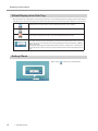
VPanel Display in the Task Tray
When the VPanel icon is displayed in the task tray, the status of a connected milling machine is always monitored. The display
of the VPanel icon changes depending on the status of the milling machine. The meanings of the displays are shown below.
Indicates that at least one of the connected milling machines is on (is online).
Indicates that all the connected milling machines are off.
Indicates that an error has occurred on at least one of the connected milling machines.
If you hover the mouse pointer over this icon, you can check which machine has the error.
Messages are displayed automatically if an error occurs, during milling, and in similar situations. Even after the message disappears, if you hover the mouse pointer over this icon, the
status of each connected machine (such as Ready, Milling, Finished, Completed, or Offline)
will be displayed.
Messages prompting you to perform maintenance (such as "Spindle run-in required") will
also be displayed. In these situations, perform the maintenance work indicated by the message.
Exiting VPanel
Right-click on
6
1. Operation Screen
in the task tray and click [Exit].
VPanel Window and Functions
Top Window
The top window displays the statuses of connected milling machines and an output list of milling data. Output of milling
data can also be executed in this window.
No.
Displayed content
Details
: Milling data can be received.
: The power of the milling machine is off.
: Operation is in progress.
Machine operation status
: An error has occurred.
: Operation is paused.
: The front cover is open.
: Milling is complete. (Will change to READY if the front cover
is closed.)
Name of connected machine
Displays the ID and name of the connected machine. The ID of machines
with the power turned off are shown with [-].
If you click the name of a connected milling machine, the status light of the
milling machine will flash. This allows verification of a connected machine
when multiple machines are connected.
Remaining time graph
The estimated milling time and a progress bar are displayed.
Milling bur work time
Displays the name of the tool selected in "Tool management," the current
work time, and the time when it must be replaced.
For example, "00h01m/06h00m" indicates that "00h01m" is the work time
and "06h00m" is the replacement time of the tool.
Milling machine status
Displays the operation status, spindle speed, milling time, etc. The information displayed is for the machine that has the radio button to the left of the
name selected.
Output list
Displays the data being milled, the milling data in standby, and the milling
progress.
Output a file
Cancel
Milling bur management
Settings
Outputs milling data.
P. 24"STEP 3: Outputting Milling Data"
Cancels output of milling dataCancels output of milling data and other
functions.
Allows for registration and selection of milling burs.
P. 12""Milling bur management" Dialog Box"
Displays the SETTINGS window.
P. 8""Settings" Tab", P. 9""Maintenance" Tab", P. 10""Mail" Tab"
1. Operation Screen
7
VPanel Window and Functions
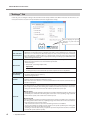
"Settings" Tab
In this tab, you can configure settings related to VPanel auto-startup and NC codes. When more than one machine is connected, the machine selected in the top window becomes the target for the setting.
Click to display the special
website in your Internet
browser.
NC code with
decimal point
Select the how to interpret numbers in NC codes. With "Conventional," the unit is interpreted as
millimeter (or inch) when there is a decimal point, and as 1/1000 millimeter (or 1/10000 inch)
when there is no decimal point. With "Calculator," the unit is always interpreted as millimeter
(or inch) regardless of whether there is a decimal point. Select the scope of the application
when selecting "Calculator." Select an appropriate setting according to your CAM or NC code.
Initial setting: Conventional
When multiple machines are connected to one computer, it's necessary to set IDs for the machines. Select the machine to use in the VPanel top window.
Initial setting: A
Machine ID
"Setup Guide" ("Connecting Multiple Units")
Important
To change an ID, be sure to follow the procedure explained in the "Setup Guide."
Run VPanel at
PC start-up
When this is checked, VPanel will start automatically when Windows starts up, and the VPanel
icon will be displayed in the task tray.
Initial setting: Checked
Version
VPanel: VPanel version
Firmware: Connected machine's firmware version
When more than one machine is connected, information for the machine selected in the top
window is displayed.
You can adjust the milling speed and the spindle speed. This is useful when you want to change
the milling speed, etc., on the fly while monitoring the milling status. Overrides are specified in
percentages. For example, if the milling data command sent from the computer is 10,000 rpm,
setting the override to 150% will cause the rotation speed to be 15,000 rpm.
Override
8
Milling speed
Allows adjustment of the milling bur movement speed when milling the workpiece. If the speed
specified by the command in the milling data is taken to be 100%, inputting a large value will
result in faster speeds, and a small value in slower speeds.
Spindle speed
You can adjust the spindle speed during milling. If the rotation specified by the command in
the milling data is taken to be 100%, inputting a large value will result in an increased rotation,
and a small value in a decreased rotation.
The override will return to 100% when the milling machine is turned OFF.
In the top window, the spindle speed is shown as the speed specified by the milling data
command and not the speed after the override.
Setting an override does not let you perform operations beyond the machine's maximum
or minimum speeds (rotation speeds).
1. Operation Screen
VPanel Window and Functions
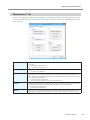
"Maintenance" Tab
In this tab, you can perform operations related to maintenance, including automatic correction of the milling machine and
system reporting. When more than one machine is connected, the machine selected in the top window becomes the target
for the operations.
Correction
Correct the ATC magazine position or the rotary axis position. You can usually use "Automatic
correction."
P. 33"Correcting the Milling Machine"
P. 11""Manual correction" Dialog Box"
Cleaning Tool
This function is used for cleaning. Push this button to open the Cleaning tool dialog box.
P. 14""Cleaning tool" Dialog Box"
ATC
Perform tests, maintenance, and other tasks related to operation with the ATC magazine. The
"Emergency release" button is enabled when the power is turned on while the front cover is
open. Use this function if initialization cannot be performed because, for example, the milling
bur is caught on the workpiece.
P. 31"Situations Requiring Maintenance"
P. 35"Care and Storage of Detection Pin and Automatic Correction Jig"
Spindle
This function is used for long-term spindle management. "Work time" displays the work time of
the spindle. After replacing the spindle unit, click "Reset" to reset the value to 0.
P. 31"Replacing Consumable Parts"
P. 33"Correcting the Milling Machine"
Report
Displays system reports (including firmware version and total operating hours) and error logs.
Pressing the "Save file" button will collect the machine’s log information and save it to a file.
1. Operation Screen
9
VPanel Window and Functions
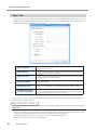
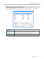
"Mail" Tab
Settings in this tab can be configured so that a notification e-mail is sent when milling finishes, when an error occurs, or
when maintenance is complete. When more than one machine is connected, all of the machines become the targets for the
settings. Check "Use mail notification" to enter each item.
Receiver address
The recipient's e-mail address. You can input more than one address by
separating with a comma.
Sender address
This becomes the sender's e-mail address. Input the mail address being used
on the computer with VPanel installed.
Server host name
Enter the name of the outgoing mail server (SMTP server name) for the e-mail
address input for the sender’s address.
Server port number
Enter the outgoing mail server port number for the e-mail address input for
the sender’s address.
Use SSL connection
Check to use a security-protected connection (SSL). Configure the outgoing
mail server settings for the e-mail address input for the sender’s address.
Use SMTP authentication
User name / Password
Check to use authentication when sending e-mails. Input the user name and
password for authentication. Configure the outgoing mail server settings for
the e-mail address input for the sender’s address.
Click "Send test" to send a test e-mail. If the following e-mail is received at the address specified in "Receiver address," configuration of the settings is complete.
Subject: <Machine name> Body: Test
If the e-mail fails to send, the "Windows Script Host" error message will be displayed. Check the content in the input fields again.
Important
* It may be impossible to send e-mails because of security software settings or the like. If e-mails cannot be sent, check the
settings of the security software being used as anti-virus software or for a similar purpose.
* For detailed information about the e-mail settings, consult your network administrator.
* VPanel does not support TLS connections (STARTTLS).
10
1. Operation Screen
VPanel Window and Functions
"Manual correction" Dialog Box
In this dialog, you can make corrections of the milling machine manually. Perform corrections if you want to precisely adjust
the accuracy. When more than one machine is connected, the machine selected in the top window is the target of corrections.
* Perform automatic correction before performing this correction.
Distance
Correct moving distances in the X, Y, and Z directions. Set the correction
value while considering the initial moving distance as 100%.
Initial setting: 100%
A axis back side
Correct the angle when the A axis is rotated 180 degrees. Set the correction
value while considering the initial setting as 0.00 degrees.
Initial setting: 0.00 degrees
Origin point
Correct the origins of the X, Y, and Z axes. Set the correction value while
considering the setting initial setting as 0.00 mm.
Initial setting: 0.00 mm
Clear these values when executing the automatic correction
Check to reset the values for "Distance," "Origin point," and "A axis back side"
when performing automatic correction.
Initial setting: Checked
1. Operation Screen
11
VPanel Window and Functions
"Milling bur management" Dialog Box
By selecting a milling bur to be used in this dialog box, the work time of the selected milling bur will be recorded automatically.
In addition, when the bur reaches the preset replacement time, a warning message will be displayed. When more than one
machine is connected, the machine selected in the top window is managed.
to display the milling bur for which "Milling bur registration" was performed. The
Click
stocker number of machine's ATC magazine should match the milling bur management
numbers (1 through 10). The information for the selected milling bur will be displayed on
the top window.
P. 12""Milling bur management" Dialog Box"
Milling bur information
Milling bur
Stocker number
Work time / Replacement time
Milling bur registration
Displays the work time and replacement time of the selected milling bur. When the bur
reaches the preset replacement time, a warning message will be displayed. The replacement time can be changed from "Milling bur registration." After replacing the milling bur
with a new one, click "Reset" to set the work time to 0.
Here you can register milling burs whose work time you want to manage, or remove burs
you no longer want to manage. Click here to display the "Milling bur registration" dialog box.
P. 12""Milling bur management" Dialog Box"
12
1. Operation Screen
VPanel Window and Functions
"Milling bur registration" Dialog Box
A milling bur's registration information can be changed in order to change the work time or the replacement time. When
more than one machine is connected, the milling bur for the machine selected in the top window will be the target.
Milling bur list
Displays the names, work times, and replacement times of the registered milling burs.
Milling bur info
Allows the milling bur name, work time, and replacement time of the milling bur selected
in the list to be edited. Click "Save" to overwrite and save the edited content.
Because replacement times depend on the type of milling bur or workpiece as well as the
milling conditions, adjust the replacement time value as necessary.
Add milling bur
Registers additional milling burs. You can register up to 20 milling burs.
Remove milling bur
Removes the milling bur selected in the list.
1. Operation Screen
13
VPanel Window and Functions
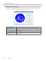
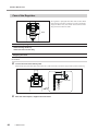
"Cleaning tool" Dialog Box
This dialog box is used when cleaning the machine. It allows the rotary axis unit, spindle, and other parts to be moved. To
verify the operation, place the mouse pointer over the button to switch the illustration.
14
Dust collector ON/OFF
Turns the dust collector ON/OFF.
(For dust collectors with a linking function and connected with a linking cable.)
Front
Moves the rotary axis unit forward. Use this function when cleaning the rotary axis unit.
Rear
Moves the rotary axis unit to the back. Use this function when cleaning the back of
the milling area.
Reverse side
Turns the clamp over. Use this function when cleaning the back side of the clamp.
Spindle
Moves the spindle unit to a visible location. Use this function when cleaning around
the spindle unit.
1. Operation Screen
2. Milling
Using / Reading the Built-In Panel......................16
Using / Reading the Built-In Panel..........................................16
Statuses Indicated by Status Light Color................................16
Switching the Power On or Off............................17
Switching the Power On........................................................17
Switching the Power Off.........................................................17
Preparing for Milling............................................18
Preparing a Workpiece (Usable Workpieces)........................18
Preparing a Milling Bur (Usable Milling Burs)........................18
Preparing Compressed Air (Setting the Regulator)...............18
Starting Milling.....................................................19
STEP 1: Mounting the Clamp to the Workpiece....................19
STEP 2: Attaching the Milling Bur..........................................23
STEP 3: Outputting Milling Data............................................24
Aborting Output.......................................................................26
Removing Milling Data in Standby from the Output List.........26
15
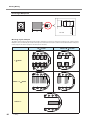
Using / Reading the Built-In Panel
Using / Reading the Built-In Panel
Operation button
ERROR
Flashes when an error has occurred.
PAUSE
Illuminates when operation is paused.
POWER
This lights up when the power is turned on.
CANCEL
Flashes when data is being cancelled and during initialization.
Milling data received while this light is flashing will be cancelled.
Operation button
Pressing this button during milling will pause or restart the machine.
Pressing and holding this button during milling will abort milling or clear some
errors.
Pressing this button in standby will rotate the rotary axis position 180 degrees. The
button will flash during initialization, spindle rotation. The button will illuminate
under any other status while the power is on.
Statuses Indicated by Status Light Color
Blue
The machine is in standby or initializing.
The light will also turn off if no operation is
performed for 30 seconds when in standby,
causing the machine to sleep.
White
When lit white, milling is being performed or
has been paused, or the front cover is open.
Also flashes when the dust collector is in
standby.
Yellow
When lit yellow, an error has occurred, and the
machine has been paused. Check the error
details shown on VPanel. Press the operation
button on the built-in panel to resume milling.
Red
When lit or flashing red, an error has occurred
and milling has been stopped. Milling cannot
be resumed.
Check the error details shown on VPanel. When
lit red, pressing and holding the operation button on the built-in panel will abort milling and
return the machine to the ready status. When
flashing, turn off the power once and start up
the machine again.
Off
The light turns off when the power is turned
off or the machine in the sleep state.
Status
light
16
2. Milling
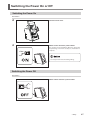
Switching the Power On or Off
Switching the Power On
Procedure
Close the front cover.
Switch on the machine's power switch.
The machine starts initialization. When the status light
stops flashing and remains steadily lit, initialization is
complete.
Do not open the front cover during milling.
Switching the Power Off
Procedure
Switch off the machine's power switch.
2. Milling
17
Preparing for Milling
Preparing a Workpiece (Usable Workpieces)
Workpiece Materials
Zirconia, Wax, PMMA, Composite resin, PEEK, Gypsum
Type
Size (Unit: mm)
Step section: 98.5 mm (diameter), 10 mm (height)
Body section: 95 mm (diameter), 60 mm (height max.)
Disk type
(with step)
Pin type
Ø5.9 ±0.02
Pin diameter: 6 mm
Preparing a Milling Bur (Usable Milling Burs)
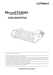
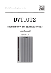
The figure below shows the size of usable milling burs.
Shank diameter: Ø4 mm
Length: 40 to 55 mm
*The shape of the milling bur is merely an example. Select the milling bur that matches the application. Contact your authorized Roland DG Corporation dealer to purchase milling burs.
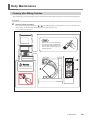
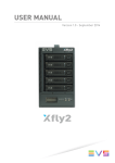
Preparing Compressed Air (Setting the Regulator)
WARNING
Turn the air pressure adjustment knob slowly and carefully.
Otherwise, the machine may move suddenly, posing a risk of injury.
Upper knob
(The air pressure
adjustment knob)
Loosen
(Decrease
the pressure.)
Tighten
(Increase the
pressure.)
Pull up on the upper knob (The air pressure
adjustment knob).
Slowly turn the upper knob.
Push down on the upper knob.
When supply of air starts, the air starts to flow
and the pressure drops. When the pressure has
dropped, adjust the regulator to have an appropriate value again. (Air is supplied when the spindle
rotates or when the tool is replaced.)
Recommended Set Pressure
0.05 MPa
Zirconia
Wax
Composite resin
0.2 MPa
PMMA
PEEK
Gypsum
Be sure to configure the regulator to 0.2 MPa or lower. Anything higher may result in a malfunction.
18
2. Milling
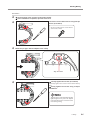
Starting Milling
STEP 1: Mounting the Clamp to the Workpiece
The mounting method differs depending on the workpiece type and size.
P. 18"Preparing a Workpiece (Usable Workpieces)"
For Disk Workpieces
P. 20"For Pin-Type Workpieces"
Close the front cover and turn on the power switch.
P. 17"Switching the Power On"
Once initialization completes, open the front cover.
Loosen the screws about 3 turns using a torque
driver. (2 locations)
Use the included spare screws when a
screw is lost or worn.
Mount the workpiece in the clamp.
Mount the workpiece so that it touches the back of the clamp on the right side.
Loosely tighten the screws. (2 locations)
Alternately tighten the screws in two locations little by
little.
Firmly tighten the screws using a torque
screwdriver.
Tightening only one of the screws at a
time may cause the workpiece to break
or the screws to become loosened during milling.
2. Milling
19
Starting Milling
Pin size
Ø5.9 ±0.02
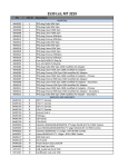
For Pin-Type Workpieces
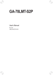
Mounting layout examples
The figure shows examples of the maximum number of workpieces that can be attached according to size, and their layout.
Workpiece sizes are limited by the number of workpieces mounted in the machine, and the number of mountable workpieces
is limited by the size of the workpieces mounted in the machine.
W
L
20mm
20mm < L
50mm < L
20
2. Milling
50mm
15 mm
15mm < W
22 mm
Starting Milling
Procedure
Close the front cover and turn on the power switch.
Once initialization completes, open the front cover.
Loosen the screws about 3 turns using a torque
driver. (2 locations)
Use the included spare screws when a
screw is lost or worn.
Mount the pin-type material adapter to the clamp.
Align the marks.
Loosely tighten the screws. (2 locations)
Alternately tighten the screws in two locations little by
little.
Firmly tighten the screws using a torque
screwdriver.
Tightening the screws without first lightly
tightening them may cause the adapter
to become tilted or the screws to become
loose during milling.
2. Milling
21
Starting Milling
Use a torque driver to loosen the screws holding
the workpiece in position.
Use the included spare screws when a
screw is lost or worn.
Mount the workpiece on the pin-type material adapter.
Make sure the recessed portion of the workpiece is oriented downward, align the protrusion for pin-type material
adapter, and insert the workpiece all the way in.
Align the recessed portion
with the protrusion.
Tighten the screws using a torque driver.
22
2. Milling
Protrusion
Starting Milling
STEP 2: Attaching the Milling Bur
Procedure
Orient with the screw
hole facing up
Milling bur holder
Attach the milling bur holder to the milling bur
positioner.
Insert the milling bur holder oriented as in the figure, and
attach it so that it reaches the back of the hole.
Milling bur
positioner
Slide the milling bur through the milling bur holder, and determine the proper position.
Insert the milling bur as in the figure, and make sure that both ends are within the areas of the milling bur positioner holes.
Secure the mounting screw using the hexagonal screwdriver.
Mounting screw
Both ends of the milling bur
are within the A and B areas.
Set the milling bur in the ATC magazine.
Insert firmly as far as possible. Up to 10 milling burs can be set. The stocker numbers are shown on the surface of the
magazine.
Insert the milling bur firmly.
OK
Not OK
2. Milling
23
Starting Milling
STEP 3: Outputting Milling Data
* You can also use commercial CAM software to output milling data. For information on compatible CAM software, contact
your authorized Roland DG Corporation dealer.
WARNING
Be sure to turn on the dust collector.
Milling Waste and workpieces are flammable and toxic.
WARNING
Never use a vacuum cleaner to clean up milling Waste.
Picking up fine cuttings using an ordinary vacuum cleaner may
result in a fire or explosion.
Procedure
In the top window of VPanel, select the
machine to output.
Click the radio button to the left of the name of the
machine to operate.
Click
.
The "Output a file" window will appear.
Click "Add."
Select the milling data, and click "Open."
The "Open" window will appear.
The selected milling data is displayed in the data
list of the "Output a file" window.
Repeat steps
to
to output the milling data
continuously.
Verify that the workpiece and the milling bur are set in the machine.
P. 23"STEP 2: Attaching the Milling Bur"
24
2. Milling
Starting Milling
Click "Output."
Changing the data list order
You can change the output order by selecting the milling data in the data list and clicking
(The milling data is output from the top of the data list.)
or
.
Removing milling data from the data list
To remove milling data from the output list, select the milling data in the data list and click "Remove."
Adding milling data by dragging and dropping
You can add milling data by dragging and dropping data on the window displayed in steps
and .
Click [OK].
The output milling data is displayed in the output
list of the top window, and milling starts.
A sound will be emitted when milling has finished.
The estimated milling time and a
progress bar are displayed next
to the name of the connected
machine.
Do not open the front cover during milling. To ensure safety, opening the front cover while data is being output
will cause an emergency stop to occur.
P. 54"Responding to Error Messages"
Open the front cover after the status light turns blue.
2. Milling
25
Starting Milling
Aborting Output
Procedure
In the top window of VPanel, select the machine for
which output will be aborted.
Click
.
The message shown in the figure will be displayed.
To abort output, click [OK].
Click [Cancel] to not abort the output.
Removing Milling Data in Standby from the Output List
Procedure
In the top window of VPanel, select the machine to edit from the output list.
Right-click the mouse on the milling data to remove
from the output list, and click [Cancel].
Only milling data in standby can be removed (milling data in the
second or following positions from the top of the output list).
26
2. Milling
3. Maintenance
Maintenance Precautions..........................................28
Maintenance Precautions............................................................... 28
Daily Maintenance ....................................................29
Cleaning after Milling Finishes....................................................... 29
Periodic Maintenance................................................31
Situations Requiring Maintenance................................................. 31
Replacing Consumable Parts........................................................ 31
Running In the Spindle (Warm-up)................................................. 32
Correcting the Milling Machine....................................................... 33
Care and Storage of Detection Pin and Automatic Correction Jig.. 35
Retightening the Collet................................................................... 36
Care of the Regulator.................................................................... 38
27
Maintenance Precautions
Maintenance Precautions
WARNING
Never use a pneumatic blower.
This machine is not compatible with a pneumatic blower. Milling waste may get inside the
machine and cause fire or electrical shock.
WARNING
Never use a solvent such as gasoline, alcohol, or thinner to perform cleaning.
Doing so may cause a fire.
WARNING
Never use a vacuum cleaner to clean up milling waste.
Picking up fine cuttings using an ordinary vacuum cleaner may result in a fire or explosion.
WARNING
Do not touch the spindle unit or the surrounding areas immediately after milling has
ended.
Doing so may result in burns.
CAUTION
Be careful around the milling tool.
The milling tool is sharp. Broken milling tools are also dangerous. To avoid injury,exercise
caution.
This machine is a precision device. Carry out daily care and maintenance.
Carefully clean away milling waste. Operating the machine with milling waste present may cause a malfunction.
Never install in an environment where silicone substances (oil, grease, spray, etc.) are present. Doing so may cause
poor switch contact or ionizer damage.
Never lubricate any location not specified in this manual.
28
3. Maintenance
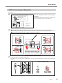
Daily Maintenance
Cleaning after Milling Finishes
After milling finishes, clean the milling area using a commercially available brush or the dust collector. Also clean the milling bur.
Procedure
Clean the inside of machine.
Clean off any milling waste around areas
to
in the following figure, as milling waste in these areas may affect the
milling results. Use the Cleaning tool dialog box to clean the rotary axis unit.
P. 14""Cleaning tool" Dialog Box"
With the dust collector operating,
use a commercially available brush
to brush off the milling waste, and
use the dust collector to pick up
the milling waste.
Do not directly touch
the inside of the ionizer.
3. Maintenance
29
Daily Maintenance
30
Part
Detection
to be pin
wiped
3. Maintenance
Use the included cloth for care to wipe off any dirt
from the portion indicated in the figure.
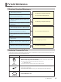
Periodic Maintenance
Situations Requiring Maintenance
When installing the machine
P. 32"Running In the Spindle (Warm-up)"
P. 33"Correcting the Milling Machine"
When replacing the spindle unit
When the machine has not been used for a prolonged period
P. 32"Running In the Spindle (Warm-up)"
Before you start using the machine in low room
temperature
When installing the machine in a different location
P. 33"Correcting the Milling Machine"
When the milling position is misaligned
When symptoms such as a hole in the Z direction
occurs
Once a month
P. 36"Retightening the Collet"
When the work time of the spindle exceeds 200
hours
P. 38"Care of the Regulator"
When water or dust accumulates on the regulator
Replacing Consumable Parts
A replacement manual is included with purchased products. For information on how to perform replacement, refer to the
replacement instruction manual included with the part.
Part name
Replacement time / Guideline
When the total work time of the spindle exceeds 2,000 hours (with slight
variation depending on the work situation).
You can use VPanel to view the total work time of the spindle.
P. 9""Maintenance" Tab"
The replacement spindle unit comes with a collet and belt.
Spindle unit
If the collet is deformed
If an overload error or other error occurs, the collet may have become deformed.
Collet
If the spindle belt is worn
Spindle belt
3. Maintenance
31
Periodic Maintenance
Running In the Spindle (Warm-up)
To stabilize the rotation of the spindle, a spindle run-in (warm-up) may be needed.
Cases Where You Need to Perform This Task
When you finish installing the machine
When the spindle unit is replaced
When the machine is not used for a prolonged period
Before you start using the machine in low room temperature
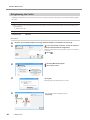
Procedure
Close the front cover and turn on the power.
Show VPanel.
In the top window of VPanel, select the machine
to operate.
P. 5"Displaying VPanel"
Click the radio button to the left of the name of the machine
to operate.
Click
.
The [Settings] screen will appear.
Click the [Maintenance] tab.
Click [Spindle run-in].
32
Click [OK].
Spindle run-in starts.
"Spindle run-in is completed" is displayed.
3. Maintenance
Periodic Maintenance
Correcting the Milling Machine
The accuracy of the milling machine may vary if it is used for a long period of time or the surrounding environment changes.
With automatic correction, the ATC magazine and the rotary axis will be in the right position.
Cases Where You Need to Perform this Task
When you finish installing the machine
When you finish moving the machine
When the cutting position is misaligned
When there is a level difference or a hole is created in the Z direction, etc. in cutting result
Required Items
·Detection pin · Automatic correction jig ·Torque driver · Cloth for care
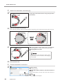
1.
Install the detection pin.
Clean off any milling waste around the clamp.
P. 29"Cleaning after Milling Finishes"
Use the supplied cloth for care to clean the detection pin, automatic correction jig, and central
protrusion on the ATC magazine.
If any dirt is affixed, correction might not occur properly.
Part to be wiped (Detection point )
Detection pin
Clean the tip
as well
Central protrusion on the
ATC magazine
Automatic correction jig
Also wipe the
rear side.
Install the detection pin to the ATC magazine's No. 10 position.
Insert the detection pin firmly.
Detection pin
OK
Not OK
3. Maintenance
33
Periodic Maintenance
2.
Attach the automatic correction jig.
Loosen the screws about 3 turns using a torque driver.
(2 locations)
Attach the automatic correction jig.
Push in until the protrusion comes into contact with the clamp. The jig can be attached with either surface facing up.
Loosely tighten using a torque driver. (2 locations)
Alternately tighten the screws in two locations little by little.
Fully tighten the screws.
Tightening the screws without first lightly tightening them may cause the automatic correction jig to
become tilted.
3.
Close the front cover.
Perform automatic correction.
Show VPanel.
P. 5"Displaying VPanel"
In the top window of VPanel, select the machine to
operate.
Click the radio button to the left of the name of the machine to
operate.
Click
.
The [Settings] screen will appear.
34
3. Maintenance
Periodic Maintenance
Click the [Maintenance] tab.
Click [Automatic correction].
Make sure that the work displayed on the screen is
complete.
Click [OK].
Automatic correction starts.
Automatic correction is complete once the screen in the figure is
displayed.
Click [OK].
Once automatic correction is complete, remove the detection pin and the automatic correction jig.
Turn the screws securing the automatic correction jig about 2 times to remove them. Store the detection pin and the
automatic correction jig in the storage compartment.
Care and Storage of Detection Pin and Automatic Correction Jig
For correction, use the detection pin and the automatic correction jig. The presence of rust, scratches, or grime on the detection pin or the automatic correction jig makes accurate detection impossible, which in turn may make it impossible to
perform milling as intended, and may even damage the machine.
Care and Storage
Before use, wipe clean using a dry clean cloth (included with product), and make sure that no dust, rust, or scratches are
found.
Store the detection pin and the automatic correction jig in the storage compartment.
3. Maintenance
35
Periodic Maintenance
Retightening the Collet
Continuous cutting will cause the collet to become loose, making it easy for the milling bur to come off. Periodically retighten
the collet.
Recommended Interval for Procedure
Once a month, or when the total work time of the spindle exceeds 200 hours (with slight variation depending on the
work situation).
P. 9""Maintenance" Tab"
Required Items
• Detection pin
• Spanner
Procedure
Remove any mounted workpiece, pin-type material adapter, or automatic correction jig.
In the top window of VPanel, select the machine
with the collet that will be retightened.
Click the radio button to the left of the name of the machine
to operate.
Click
Click the [Maintenance] tab.
Click "Open collet."
Click [OK].
Moving the spindle unit will open the collet.
36
.
The window shown in the figure appears.
Click [OK].
3. Maintenance
Periodic Maintenance
Fit the spanner onto the collet.
Insert the detection pin into the collet.
If the detection pin cannot be inserted, repeat the operation in
.
Collet
Detection
pin
Spanner
Use the included spanner and keep the detection pin
inserted. If the detection pin is not inserted, the collet may become deformed, resulting in lower milling
accuracy.
Tighten the collet with the spanner while holding
the detection pin.
Tightening is sufficient once the spanner and the tip
of the spindle unit (shaded portion in the figure to the
left) begin to rotate together.
Remove the detection pin and the spanner, and
close the front cover.
Click the [Maintenance] tab.
Click "Close collet."
The procedure is complete if the spindle unit moves and
"The operation was completed." is displayed.
The window shown in the figure appears.
Click [OK].
3. Maintenance
37
Periodic Maintenance
Care of the Regulator
The regulator is equipped with a filter that becomes filled
with drainage (moisture and dust) over time. Periodically
empty the drain. Also, if the inside of the bowl becomes
dirty, remove and wash the bowl.
Bowl
Situations Requiring This Work
When drainage builds up
When the bowl becomes dirty
Emptying the Drain
Procedure
Loosen the lower knob little by little.
Material may spray out of the drain at this time. Use a cloth or the like to catch the spray and keep it from scattering.
Lower knob
38
After the drain empties, retighten the lower knob.
3. Maintenance
Periodic Maintenance
Cleaning the Bowl
WARNING
Be sure to bleed off the air pressure before removing the regulator bowl.
Failure to do so may result in a rupture or components flying off.
WARNING
Before removing or attaching the regulator and before performing maintenance, make
sure that the bowl is securely attached.
If the bowl is not properly attached, it may come flying off when compressed air is supplied.
Procedure
Stop the supply of compressed air.
Loosen the screws about 3 turns in the locations
shown in the figure to the left using a torque
driver. (2 locations)
Remove the regulator.
Remove the bowl from the regulator.
Wash the bowl using a neutral detergent.
WARNING
Loosen
Tighten
Bowl
Clean the regulator bowl using a neutral detergent.Never use solvents such as gasoline,
alcohol, or thinner.
Using solvents may degrade the bowl and may result
in a rupture.
After making sure that the bowl is completely dry, retighten the bowl.
Attach the regulator to the machine.
3. Maintenance
39
4. Troubleshooting
Machine Trouble........................................................41
Initialization is Not Performed or Initialization Fails........................ 41
The Operation Button Does Not Respond...................................... 41
VPanel Does Not Recognize the Machine..................................... 41
No Data is Being Output to the Machine, or the Machine will Not Operate Even Though Data is Being Output.......................................... 42
The Computer Shuts Down when Connecting Multiple Machines.. 42
The Spindle Does not Rotate......................................................... 42
The Ionizer is Ineffective (Milling Waste Collects Around the Milling Area).. 43
Compressed Air Does Not Come Out............................................. 43
Automatic Correction Fails.............................................................. 43
The Milling Bur Management Information was Lost....................... 44
Milling Quality Problems............................................45
The Milled Surface is Not Attractive................................................ 45
There is a Line of Level Difference in the Milling Results............... 45
Chipping (Edges of Milling Products Become Chipped) Occurs.... 45
A Hole Opens in the Milling Results............................................... 46
The Dimensions of the Milling Results Do Not Match.................... 47
Installation Trouble...................................................48
Installing the Driver Separately...................................................... 48
Installing the Softwear and the Electronic Manual Separately...... 50
Driver Installation Is Impossible..................................................... 51
Uninstalling the Driver.................................................................... 52
Uninstalling VPanel........................................................................ 53
Responding to Error Messages.................................54
40
Machine Trouble
Initialization is Not Performed or Initialization Fails
Is the front cover open?
Keep the front cover closed during startup. For
safety, initialization is not performed when the cover
is open at startup.
-
Is the milling bur caught on anything?
The milling bur attached to the spindle unit may fail
to perform initialization if it is caught on the workpiece or rotary axis unit. Try to detach the milling bur
using the emergency release function in VPanel.
P. 9
Is anything caught on the spindle
unit or rotary axis unit?
Open the maintenance cover, and make sure that no
workpiece or milling waste is caught.
-
The Operation Button Does Not Respond
Is the front cover open?
This machine restricts some operations when the
front cover is open. Close the cover.
-
Are you wearing gloves?
The operation button will not respond if you are
wearing gloves. Operate the button with a bare hand.
-
VPanel Does Not Recognize the Machine
Is the cable connected?
Make sure that the cables are connected.
Refer to "Setup Guide" ("Connecting the Cables") to
perform the work.
-
Is the driver installed correctly?
If the connection to the computer is not made in
the procedure described, the driver may fail to
install correctly. VPanel will not function normally if
the driver is not configured correctly. Check again
to ensure that the connection was made using the
correct procedure.
P. 48
Did you verify the connection procedure when connecting more than
one machine?
There is a possibility that the connection procedure
was performed incorrectly. Make sure that connections were performed correctly.
Refer to "Setup Guide" ("Connecting Multiple Units")
to perform the work.
-
Was the machine ID changed?
If the machine's ID has been changed, restart the
machine.
P. 5
4. Troubleshooting
41
Machine Trouble
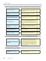
No Data is Being Output to the Machine, or the Machine will Not Operate Even Though Data is Being Output
Is the front cover open?
If the front cover is open, the machine will not start
milling even if milling data is being received. Close
all of the covers and press the operation button to
start milling.
-
Does VPanel recognize the machine?
Verify that a message other than "Offline ("OFF"
display) is shown on VPanel.
-
If multiple machines are connected,
is the correct machine selected?
Select the machine to output milling data to on the
VPanel screen.
-
Is operation paused?
Operation is paused if the PAUSE LED is lit. When the
machine is paused, milling stops and some operations are restricted. Quickly pressing the operation
button of the machine will cancel the pause. Pressing and holding on the operation button will abort
milling.
-
Is initialization or a data cancel in
progress?
Milling data received during initialization or a data
cancel will be cancelled. Make sure to output milling data after confirming that the machine is in the
standby status.
-
Is the milling data correct?
Check the milling data.
-
Has an error occurred?
The ERROR LED will flash if an error occurs. A description of the error is displayed in VPanel.
P. 54
The Computer Shuts Down when Connecting Multiple Machines
Are machines with the same ID
connected to the computer at the
same time?
Connecting more than one machine with the same
ID to a computer at the same time may cause the
computer to shut down. If the computer shuts down,
turn off the power of all connected machines, and
then disconnect the USB cables from the computer.
Restart the computer, and then start VPanel. If VPanel
will not start, reinstall it. After that, configure the settings so that no machines are assigned the same ID.
Refer to "Setup Guide" ("Connecting Multiple Units")
to perform the work.
-
The Spindle Does not Rotate
Is the spindle belt damaged or disconnected?
42
4. Troubleshooting
Check inside the maintenance cover. If the spindle
belt is damaged, replace it.
P. 31
Machine Trouble
The Ionizer is Ineffective (Milling Waste Collects Around the Milling Area)
Is the workpiece being cut a PMMA
workpiece?
The ionizer (static electricity eliminator) is only effective with PMMA. It has no effect on zirconia and wax
workpieces.
-
Is there milling waste around the
ionizer?
If milling waste is found, clean with a dust collector.
Also the ionizer's effectiveness will decrease if milling waste is present. Do not touch inside the ionizer.
P. 29
Is the machine grounded?
The ionizer will not function properly if the machine
is not grounded.
-
Compressed Air Does Not Come Out
Does the operation require compressed air?
Compressed air is only supplied during some operations, such as when the spindle is rotating or when
replacing the milling bur.
-
Is the regulator properly connected
and the pressure settings correctly
configured?
Check the connection. Also, check whether the regulator indicates zero. If the set pressure of the regulator is zero, compressed air will not be supplied.
Refer to "Setup Guide" ("Preparing the Regulator").
P. 18
Is the knob at the bottom of the
regulator open?
The compressed air will escape if the knob at the bottom of the regulator is open.
P. 38
Is the automatic correction jig, detection pin, or ATC magazine dirty?
Clean away any grime on the automatic correction
jig, the detection pin, or the ATC magazine. Fouling
due to buildup of milling waste or the like on any of
these may impede correct sensor operation, making
detection impossible.
P. 33
Is the automatic correction jig properly attached?
Verify that the automatic correction jig is properly
attached.
P. 33
Is the detection pin properly attached?
Verify that the detection pin is properly attached.
Check the position of the milling bur holder on the
detection pin.
Refer to "Setup Guide" ("Dimensional Drawings "Detection Pin Dimensions)
P. 33
Automatic Correction Fails
4. Troubleshooting
43
Machine Trouble
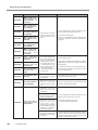
The Milling Bur Management Information was Lost
Was the machine name (printer
name) changed?
44
4. Troubleshooting
Milling bur info is saved per machine name (printer
name). Before changing the machine name (printer
name), make sure to record the milling bur info separately. Milling bur info can be recovered by returning
the machine name (printer name) to the original
name.
-
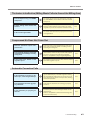
Milling Quality Problems
The Milled Surface is Not Attractive
Is the workpiece firmly secured in
place?
Check the mounting condition of the workpiece.
Fasten the workpiece in place securely so that it will
not slip out of place or come loose because of milling bur pressure or vibration during milling.
P. 19
Is the milling bur worn?
If the same milling bur is used for milling for a long
period of time, it will become worn and affect milling
results. Try replacing the milling bur with a new one.
The work time of the milling bur can also be managed in VPanel.
P. 12
Are the milling conditions too
strict?
Strict milling conditions may affect milling results.
Review the CAM milling conditions.
-
There is a Line of Level Difference in the Milling Results
Is the machine out of correction?
The origin point may become out of position due to
prolonged use or relocating the machine, which can
result in a line of level difference. Perform automatic
correction. If expected results cannot be obtained
even after performing automatic correction, perform
manual correction. With manual correction, changing
the Y value in Origin point may improve the situation.
P. 33
Are the CAM milling settings correct?
Depending on the milling conditions, a line of level
difference may occur. Review the CAM milling conditions.
-
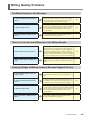
Chipping (Edges of Milling Products Become Chipped) Occurs
Is the installation base of the machine secure?
The vibration from milling can shake the installation
base. Install the machine in a level and stable location.
-
Is the workpiece firmly secured in
place?
Check the mounting condition of the workpiece. If
the workpiece is not mounted correctly, it may come
loose during milling and may become misaligned.
P. 19
Is the milling bur worn?
If the same milling bur is used for milling for a long
period of time, it will become worn and affect milling
results. Try replacing the milling bur with a new one.
The work time of the milling bur can also be managed in VPanel.
P. 12
Are the milling conditions too
strict?
Strict milling conditions may affect milling results.
Review the CAM milling conditions.
4. Troubleshooting
-
45
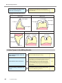
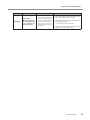
Milling Quality Problems
If the thickness of workpieces is excessively thin,
chipping is likely to occur. Check the shape specified
in the CAD data.
Is the thickness specified in the
CAD data excessively thin?
-
Recommended CAD data thickness
Unit:mm
Front tooth
Molar tooth
1.5 or higher
1.0 or higher
1.5 or higher
1.0 to 1.2
1.5 or higher
0.8 or higher
0.8 or higher
Veneer
Onlay
1.5 or higher
1.0 or higher
Inlay
1.0 or higher
0.4 or
higher
0.6 or higher
0.5 to 1.5
A Hole Opens in the Milling Results
46
Do the milling bur diameter and
ATC magazine number match the
CAM settings?
Check the CAM's milling bur settings.
Is the machine out of correction?
The origin point may become out of position due to
prolonged use or relocating the machine, which can
affect milling results. Perform automatic correction.
If expected results cannot be obtained even after
performing automatic correction, perform manual
correction. With manual correction, changing the Z
value in the + direction in Origin point may improve
the situation.
Are the milling conditions too
strict?
Strict milling conditions may affect milling results.
Review the CAM milling conditions.
4. Troubleshooting
-
P. 33
-
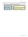
Milling Quality Problems
The Dimensions of the Milling Results Do Not Match
Does the milling bur diameter
match the CAM settings? Is the
CAM shrinking percentage setting
proper for the workpiece?
Check the CAM settings.
-
Does the settings of the sintering
program match the workpiece?
Check the set temperature of the sintering program
to see if it matches the workpiece of the manufacturer used.
-
4. Troubleshooting
47
Installation Trouble
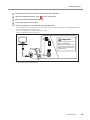
Installing the Driver Separately
With this machine, you can also install the driver, software, and electronic-format manual all at once. To install all
at once, see "Setup Guide" ("Installing the Software").
Procedure
Before installation, confirm that the machine and the computer are not connected with the USB cable.
Log on to Windows as an “Administrator.”
Insert the Roland Software Package CD into the CD-ROM drive of the computer.
When the automatic playback window appears, click [Run menu.exe]. If a [User Account Control] window appears, click
[Allow] or [Yes], and continue with the installation. The setup menu screen appears automatically.
If the driver is already installed, uninstall it.
P. 52"Uninstalling the Driver"
Go to Step
if the driver is not installed or if it has been uninstalled.
Click [Custom Install] for the "DWX-51D Software."
Click [Install] for the "Windows Driver."
Windows 8/ 8.1
Windows Vista/7
48
4. Troubleshooting
When the window shown in the figure appears, click [Install].
If the window shown in the figure appears, click [Install
this driver software anyway].
Installation Trouble
Follow the on-screen instructions to proceed with the installation.
When the installation finishes, click
on the setup menu.
Remove the Roland Software Package CD.
Turn on the power to the machine.
Connect the machine to the computer using the USB cable.
If connecting more than one unit of this machine to a single computer, refer to "Setup Guide" ( "Connecting Multiple Units").
For the USB cable, use the included cable.
Do not use a USB hub. Connection may not be possible.
Secure the USB cable with a cable clamp.
Important
Do not bind the power cord
with the cable clamp.
Binding the USB cable and
the power cord may produce
noise or the like, resulting in
a malfunction.
The driver will be installed automatically.
4. Troubleshooting
49
Installation Trouble
Installing the Softwear and the Electronic Manual Separately
Log on to Windows as an “Administrator.”
Insert the Roland Software Package CD into the CD-ROM drive of the computer.
When the automatic playback window appears, click [Run menu.exe]. If a [User Account Control] window appears, click
[Allow] or [Yes], and continue with the installation. The setup menu screen appears automatically.
Click [Custom Install] for the "DWX-51D Software."
Click [Install] for "VPanel" or "Manual."
Follow the on-screen instructions to proceed with the installation.
When the installation finishes, click
on the setup menu.
Remove the Roland Software Package CD-ROM.
With this machine, you can also install the driver, software, and electronic-format manual all at once. To install
all at once, see "Setup Guide" ("Installing the Software").
50
4. Troubleshooting
Installation Trouble
Driver Installation Is Impossible
If installation quits partway through or when VPanel does not recognize the machine, the driver may not have been installed
correctly. In such cases, perform the following procedures. (If procedure A does not solve your problem, perform procedure B.)
Windows 8 / 8.1 (procedure A)
1. Connect the machine to the computer with the USB cable and turn on the machine.
2. Click [Desktop].
3. Point to the lower-right corner of the screen to display the charms, and click [Settings].
4. Click [Control Panel].
5. Click [View devices and printers].
6. Check that the model you are using is displayed under "Unspecified."
7. Right-click the icon of the model you are using, and then click [Remove device].
8. When the message "Are you sure you want to remove this device?" is displayed, click [Yes].
9. Check that the icon for the model you are using is no longer displayed under "Unspecified."
10. Temporarily disconnect the USB cable connecting the machine to the computer, and then reconnect these devices.
If the printer icon for the machine you are using is displayed under "Printer," the driver has been successfully installed.
If you could not solve your problem by following this procedure, perform the procedure under "Windows 8/8.1 (procedure B)."
Windows 8 / 8.1 (procedure B)
1. Connect the machine to the computer with the USB cable and turn on the machine.
2. If the [Found New Hardware] appears, click [Close] to close it. Disconnect any USB cables for printers or other such equipment other than this machine.
3. Click [Desktop].
4. Point to the lower-right corner of the screen to display the charms, and click [Settings].
5. Click [PC info].
6. Click [Device Manager]. If the [User Account Control] window appears, click [Continue]. [Device Manager] appears.
7. Click [Show hidden devices] from the [View] menu.
8. In the list, find [Printers] or [Other devices], then double-click it. Under the selected item, click the name of the model you
are using or [Unknown device].
9. Go to the [Action] menu, and click [Uninstall].
10. In the "Confirm Device Uninstall" window, click [OK]. Close [Device Manager].
11. Detach the USB cable from the computer, and then restart Windows.
12. Uninstall the driver. Carry out the steps from step 3 on page 52 “Uninstalling the Driver (Windows 8/8.1)” to uninstall
the driver.
13. Reinstall the driver again following "Setup Guide" ("Installing the Software") or P. 48"Installing the Driver Separately".
Windows 7 (procedure A)
1. Connect the machine to the computer with the USB cable and turn on the machine.
2. From the [Start] menu, click [Devices and Printers].
3. Check that the model you are using is displayed under "Unspecified."
4. Right-click the icon of the model you are using, and then click [Troubleshooting].
5. When a screen is displayed with the message "Install a driver for this device," click [Apply this fix].
6. If a message is displayed asking you to "Set as default printer," click [Skip this fix].
7. When the message "Troubleshooting has completed" is displayed, click [Close the troubleshooter].
If the printer icon for the machine you are using is displayed under "Printer," the driver has been successfully installed.
If you could not solve your problem by following this procedure, perform the procedure under "Windows 7 (procedure B)."
Windows 7 (procedure B)
1. If [Found New Hardware] appears, click [Close] to close it.
2. Click the [Start] menu, then right-click [Computer]. Click [Properties].
3. Click [Device Manager]. The [User Account Control] appears, click [Continue]. [Device Manager] appears.
4. Click [Show hidden devices] from the [View] menu.
5. In the list, find [Other devices] , then double-click it. Under the selected item, click the name of the model you are using
or [Unknown device].
6. Go to the [Action] menu, and click [Uninstall].
4. Troubleshooting
51
Installation Trouble
7. In the "Confirm Device Uninstall" window, select [Delete the driver software for this device.], then click [OK]. Close [Device
Manager].
8. Detach the USB cable from the computer, and then restart Windows.
9. Uninstall the driver. Carry out the steps from step 3 on page 52 “Uninstalling the Driver (Windows Vista / 7)” to uninstall
the driver.
10. Reinstall the driver again according to the procedure in "Setup Guide" ("Installing the Software") or P. 50"Installing
the Softwear and the Electronic Manual Separately".
Uninstalling the Driver
When uninstalling the driver, perform the following operation.
Windows 8 / 8.1
*If the driver is uninstalled without following the procedure given below, there is a possibility that it might not be able to
be re-installed.
1. Turn off the machine and remove the cable connecting the machine to the computer.
2. Log on to Windows as an administrator.
3. Click [Desktop].
4. Point to the lower-right corner of the screen to display the charms, and click [Settings].
5. Click [Control Panel] and then click [Uninstall a program].
6. Select the driver of the machine to remove by clicking it, and then click [Uninstall].
7. The following removal confirmation message will appear. Click [Yes].
8. Click [Start] and then click [Desktop].
9. Open Explorer, and then open the drive and folder containing the driver. (*)
10. Double-click "SETUP64.EXE" (64-bit version) or "SETUP.EXE" (32-bit version).
11. If the [User Account Control] window appears, click [Allow]. The setup program for the driver starts.
12. Click [Uninstall]. Select the machine to remove and click [Start].
13. If it is necessary to restart your computer, a window prompting you to restart will appear. Click [Yes].
14. After the computer has restarted, open the Control Panel again, and click [View devices and printers].
15. If you can see the icon of the machine to remove, right-click it and click [Remove device].
(*) When using the CD, specify the folder as shown below. (This is assuming your CD drive is the D drive.)
D:\Drivers\WIN8X64 (64-bit versions)
D:\Drivers\WIN8X86 (32-bit versions)
If you're not using the CD, go to our special Easy Shape website (http://www.rolandeasyshape.com) and download the driver
for the machine you want to remove, and then specify the folder where you want to extract the downloaded file.
Windows Vista / 7
*If the driver is uninstalled without following the procedure given below, there is a possibility that it might not be able to
be re-installed.
1. Before you start uninstallation of the driver, unplug the USB cables from your computer.
2. Log on to Windows as an administrator.
3. From the [Start] menu, click [Control Panel]. Click [Uninstall a program].
4. Select the driver of the machine to remove by clicking it, and then click [Uninstall].
5. The following removal confirmation message will appear. Click [Yes].
6. From the [Start] menu, choose [All Programs], then [Accessories], then [Run], and then click [Browse].
7. Choose the name of the drive or folder where the driver is located. (*)
8. Select "SETUP64.EXE" (64-bit version) or "SETUP.EXE" (32-bit version) and click [Open], and then click [OK].
9. The [User Account Control] appears, click [Allow].
10. The setup program for the driver starts.
11. Click [Uninstall] to choose it. Select the machine to remove and click [Start].
12. If it is necessary to restart your computer, a window prompting you to restart will appear. Click [Yes].
13. The uninstallation will be finished after the computer restarts.
(*)
When using the CD, specify the folder as shown below. (This is assuming your CD drive is the D drive.)
<< Windows Vista >>
D:\Drivers\WINVISTAX64 (64-bit versions)
D:\Drivers\WINVISTAX86 (32-bit versions)
52
4. Troubleshooting
Installation Trouble
<< Windows 7 >>
D:\Drivers\WIN7X64 (64-bit versions)
D:\Drivers\WIN7X86 (32-bit versions)
If you're not using the Roland Software Package CD, go to our special Easy Shape website (http://www.rolandeasyshape.
com) and download the driver for the machine you want to remove, and then specify the folder where you want to extract
the downloaded file.
Uninstalling VPanel
When uninstalling VPanel, perform the following operation.
Windows 8 / 8.1
1. Exit VPanel. (Right-click
(VPanel icon) in the task tray and select "Exit.")
2. On the desktop, point to the lower-right corner of the screen to display the charms, and click [Settings].
3. Click [Control Panel] and then click [Uninstall a program].
4. Select "Roland VPanel for DWX-51D" and click [Uninstall].
5. Follow the on-screen instructions to uninstall.
Windows Vista / 7
1. Exit VPanel. (Right-click
(VPanel icon) in the task tray and select "Exit.")
2. From the [Start] menu, click [Control Panel] and then click [Programs and Features].
3. Select "Roland VPanel for DWX-51D" and click [Uninstall] (or "Delete").
4. Follow the on-screen instructions to uninstall.
4. Troubleshooting
53
Responding to Error Messages
This section describes the error messages that may appear on VPanel and how to take action to remedy the problem. If the
action described here does not correct the problem, if an error message not described here appears, contact your authorized
Roland DG Corporation dealer.
Error number
Message
1000-****
The % limit switch
is not found.
(% may be "X," "Y,"
"Z," "A,"or "B.")
1006-****
1017-0000
The % axis position
has been shifted.
(% may be "X," "Y,"
"Z," "A,"or "B.")
The front cover is
open.
Situation/error cause
Action
1. Turn off the power.
The operation may be
inhibited by milling
waste or an obstruction.
2. Remove any objects blocking operation of the
machine and any accumulated milling waste.
3. Turn on the power, and then restart operation.
The motor position may
have been lost.
The milling conditions
may be excessively strict.
The front cover was
opened during spindle
rotation.
(For safety, the machine
comes to an emergency
stop if the front cover is
opened while the spindle
is rotating.)
1. Remove any objects blocking operation of the
machine and any accumulated milling waste.
2. Press and hold the operation button on the
built-in panel. This will clear the error.
1. Press and hold the operation button on the
built-in panel. This will clear the error.
2. Review the CAM settings and the shape
specified in the CAD data.
To continue milling
Press the operation button on the built-in panel
to resume milling.
To stop milling
Press and hold the operation button on the
built-in panel.
Do not open the front cover while the spindle is
rotating. Doing so may affect the milling results.
1. Turn off the power.
101C-0000
The milling bur
sensor is not
found.
The operation may be
inhibited by milling
waste or an obstruction.
2. Remove any objects blocking operation of the
machine and any accumulated milling waste.
3. Turn on the power, and then restart operation.
The returning of the
milling bur failed. The
inside of the collet or
the ATC magazine might
be dirty.
101D-****
54
The % milling
bur cannot be
released.
(% may be "1 to
10")
4. Troubleshooting
1. Press and hold the operation button on the
built-in panel. This will clear the error.
2. Clicking "Open collet" in VPanel will open the
collet. Remove the milling bur.
P. 9""Maintenance" Tab"
3. Clean the ATC magazine.
The collet and milling bur
are affixed together and
cannot be separated. The
inside of the collet might
be dirty.
P. 29"Cleaning after Milling Finishes"
4. Retighten the collet.
P. 36"Retightening the Collet"
If the error occurs again even after you perform
the above operations, the collet may have
become deformed. Replace the collet with a
new one.
Responding to Error Messages
Error number
Message
Situation/error cause
The milling bur might be
broken.
Action
1. Press and hold the operation button on the
built-in panel to clear the error.
2. If the milling bur is broken, replace it with a
new one.
The milling bur holder
might be out of position.
101E-****
The % milling bur
might be broken.
(% may be "1 to
10")
3. If the position of the milling bur holder is not
appropriate, correct the position.
P. 23"STEP 2: Attaching the Milling Bur"
The milling conditions
may be excessively strict.
The collet may be worn
out.
The collet may have
come loose.
1. Press and hold the operation button on the
built-in panel. This will clear the error.
2. Review the CAM settings and the shape
specified in the CAD data.
If the error occurs again even after you perform
the above operations, the collet may have
worn out, leading to a decrease in its retention
capabilities. Replace the collet with a new one.
1. Press and hold the operation button on the
built-in panel to clear the error.
2. Retighten the collet.
P. 36"Retightening the Collet"
101F-****
The % milling
bur chucking has
slipped out.
(% may be "1 to
10")
The milling conditions
may be excessively strict.
The collet may be worn
out.
The % milling bur
is too long.
1020-****
1021-****
The % milling bur
is too short.
(% may be "1 to
10")
There is a possibility
that the position of the
milling bur holder is not
correct.
The milling bur has
not been set or it may
have been mounted
on an incorrect stocker
number.
1022-****
The % milling bur
is not found.
(% may be "1 to
10")
There is a possibility that
the ATC magazine is out
of position.
1. Press and hold the operation button on the
built-in panel. This will clear the error.
2. Review the CAM settings and the shape
specified in the CAD data.
If the error occurs again even after you perform
the above operations, the collet may have
worn out, leading to a decrease in its retention
capabilities. Replace the collet with a new one.
Replace the milling bur with one of the appropriate length (40 to 55 mm). Also check the position
of the milling bur holder.
P. 23"STEP 2: Attaching the Milling Bur"
1. Set the milling bur in the correct position
again.
If milling is in progress
Close the front cover, and press and hold the
built-in panel's operation button. Resume
milling.
Perform automatic correction.
P. 33"Correcting the Milling Machine"
Replace the collet.
The collet may be worn
out.
If the error occurs again even after you perform
the above operations, replace the spindle unit
with a new one.
4. Troubleshooting
55
Responding to Error Messages
Error number
Message
Situation/error cause
Action
1023-0000
Milling data error.
The number of
parameters is
incorrect.
1024-0000
Milling data error.
The parameter is
out of range.
1025-0000
Milling data error.
A wrong command
is detected.
1026-0000
Milling data error.
The address is not
defined.
1027-0000
Milling data error.
The parameter is
not defined.
1028-0000
Milling data error.
The operation
c a n n o t
b e
executed.
1029-0000
The spindle
experienced an
overload.
102A-0000
The spindle
experienced
overcurrent.
102B-0000
The spindle motor
temperature is
high.
102D-0000
The spindle does
not turn.
The cable may be broken
or the spindle unit may
be defective.
Turn off the power and contact your authorized
Roland DG Corporation dealer.
1030-0000
The dust collector
is not working.
M ake sure the dust
collector is connected
correctly and the power
is on.
Turn the dust collector on, and check the dust
collector settings and the filter.
There may be a problem
with the milling data
received from the computer.
The spindle stopped under a large milling load
or other cause. The following are likely reasons.
• The milling bur is worn.
• A workpiece that cannot be milled by the machine is being used.
• The milling conditions
are too strict.
1. Press and hold the operation button on the
built-in panel. This will clear the error.
2. Check the milling data.
If there is no problems with the milling data,
restart the computer, and then perform milling again.
1. Turn off the power.
2. Check the milling bur, the workpiece, and the
CAM settings as well as the shape specified in
the CAD data.
3. Allow the machine to rest for some time before turning the power on because the motor
may have overheated.
Automatic correction
may not have been
performed.
Automatic correction
may have been cancelled
before it could finish.
103B-0000
The automatic
correction is not
yet finished.
Automatic correction
may not have been
performed after
updating the firmware
to a version that required
automatic correction to
be performed again.
The VPanel and machine
firmware versions may
not match.
56
4. Troubleshooting
1. Press and hold the operation button on the
built-in panel. This will clear the error.
2. Perform automatic correction.
P. 33"Correcting the Milling Machine"
Download the latest versions of VPanel and the
machine's firmware from our special Easy Shape
website (http://www.rolandeasyshape.com),
and then install these versions.
Responding to Error Messages
Error number
103D-0000
Message
Situation/error cause
103D-0000
Milling data error.
The milling bur has
not reached the
milling position.
If the milling bur is too
short, or if the angle of
the A axis and B axis are
too large, the milling
bur may not reach the
milling position in the Z
direction.
Action
1. Press and hold the operation button on the
built-in panel. This will clear the error.
2. Check the milling bur length and the position
of the milling bur holder.
P. 23"STEP 2: Attaching the Milling Bur"
3. Review the CAM settings, and decrease the
angles of the A axis and the B axis.
4. Troubleshooting
57
DOC-1281
R1-150707