1
User's Manual
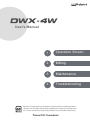
1
Operation Screen
2
Milling
3
Maintenance
4
Troubleshooting
Roland DG Corporation has developed a special website introducing dental
solutions. For the latest information regarding this machine (including manuals), see our special Easy Shape website (http://www.rolandeasyshape.com).
Contents
Contents....................................................................................................................................... 2
1. Operation Screen............................................................................................................................ 4
Displaying or Exiting VPanel........................................................................................................ 5
What is VPanel?............................................................................................................................................................................... 5
Displaying VPanel........................................................................................................................................................................... 5
VPanel Display in the Task Tray.................................................................................................................................................. 6
Exiting VPanel.................................................................................................................................................................................. 6
VPanel Window............................................................................................................................ 7
Top Window...................................................................................................................................................................................... 7
"Settings" Tab................................................................................................................................................................................... 8
"Maintenance" Tab......................................................................................................................................................................... 9
"Mail" Tab.........................................................................................................................................................................................10
"Manual correction" Dialog Box..............................................................................................................................................11
"Milling bur management" Dialog Box.................................................................................................................................12
"Milling bur registration" Dialog Box.....................................................................................................................................13
2. Milling............................................................................................................................................ 14
Using/Reading the Built-In Panel............................................................................................... 15
Using/Reading the Built-In Panel............................................................................................................................................15
Statuses Indicated by Status Light Color.............................................................................................................................15
Switching the Power On or Off................................................................................................... 16
Switching the Power On............................................................................................................................................................16
Switching the Power Off............................................................................................................................................................16
Preparing for Milling................................................................................................................... 17
Preparing a Workpiece (Usable Workpieces)......................................................................................................................17
Preparing a Milling Bur...............................................................................................................................................................17
Preparing Compressed Air (Setting the Regulator).........................................................................................................17
Filling the Coolant Tank/Replacing the Coolant................................................................................................................18
Starting Milling............................................................................................................................ 23
Milling Precautions......................................................................................................................................................................23
STEP 0: Spindle Run-In (Short).................................................................................................................................................23
STEP 1: Mounting the Workpiece...........................................................................................................................................24
STEP 2: Outputting Milling Data.............................................................................................................................................25
Aborting Output...........................................................................................................................................................................27
Deleting Standby Milling Data................................................................................................................................................27
Following Daily Operations........................................................................................................ 28
Collet Maintenance......................................................................................................................................................................28
3. Maintenance.................................................................................................................................. 32
Maintenance Precautions........................................................................................................... 33
Maintenance Precautions..........................................................................................................................................................33
Daily Care.................................................................................................................................. 34
Cleaning after Milling Finishes................................................................................................................................................34
Care of the Dummy Pin for Milling.........................................................................................................................................36
Periodic Care and Maintenance ................................................................................................ 38
Cleaning the Waterproof Plate................................................................................................................................................38
Milling Machine Correction......................................................................................................................................................39
Milling Bur Change Test.............................................................................................................................................................45
Filling the Coolant Tank/Replacing the Coolant................................................................................................................46
Care and Storage of the Automatic Correction Jig..........................................................................................................47
Care of the Regulator Bowl.......................................................................................................................................................47
Replacing Consumable Parts..................................................................................................... 49
Replacing the Spindle Unit.......................................................................................................................................................49
Milling Bur Service Life...............................................................................................................................................................49
Replacing the Coolant Tank Filter...........................................................................................................................................49
Replacing the Collet....................................................................................................................................................................53
2
Extended Periods of Non-Use / Moving the Machine................................................................ 55
Draining the Coolant Lines.......................................................................................................................................................55
Spindle Run-In (Long).................................................................................................................................................................57
Attaching the Retainers.............................................................................................................................................................59
4. Troubleshooting............................................................................................................................ 64
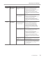
Machine Problems..................................................................................................................... 65
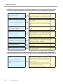
The Machine Does Not Run/Cannot Generate Output...................................................................................................65
The Operation Button Does Not Respond..........................................................................................................................65
VPanel Does Not Recognize the Machine...........................................................................................................................65
No Data Is Being Output to the Machine, or the Machine Will Not Operate Even Though Data Is Being Output...66
The Computer Shuts Down when Connecting Multiple Machines...........................................................................66
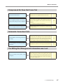
Compressed Air Does Not Come Out....................................................................................................................................67
Automatic Correction Fails........................................................................................................................................................67
The Milling Bur Management Information was Lost.......................................................................................................67
Collet Maintenance Cannot Continue Due to an Error Occurring..............................................................................68
Water Is Leaking from the Front Cover.................................................................................................................................68
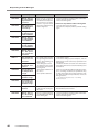
Milling Quality Problems............................................................................................................. 69
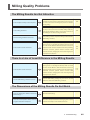
The Milling Results Are Not Attractive..................................................................................................................................69
There Is a Line of Level Difference in the Milling Results...............................................................................................69
The Dimensions of the Milling Results Do Not Match....................................................................................................69
Chipping (Edges of Milling Products Become Chipped) Occurs.................................................................................70
A Hole Opens in the Milling Results......................................................................................................................................70
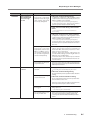
Installation Problems.................................................................................................................. 71
Installing the Driver Separately...............................................................................................................................................71
Installing the Software and the Electronic Manual Separately....................................................................................73
Driver Installation Is Impossible..............................................................................................................................................73
Uninstalling the Driver...............................................................................................................................................................75
Uninstalling VPanel......................................................................................................................................................................76
Responding to Error Messages.................................................................................................. 77
Thank you very much for purchasing this product.
To ensure correct and safe usage with a full understanding of this product's performance, please be sure to read
through this manual completely and store it in a safe location.
Unauthorized copying or transferal, in whole or in part, of this manual is prohibited.
The contents of this operation manual and the specifications of this product are subject to change without notice.
The operation manual and the product have been prepared and tested as much as possible. If you find any
misprint or error, please inform us.
Roland DG Corporation assumes no responsibility for any direct or indirect loss or damage which may occur
through use of this product, regardless of any failure to perform on the part of this product.
Roland DG Corporation assumes no responsibility for any direct or indirect loss or damage which may occur with
respect to any article made using this product.
http://www.rolanddg.com/
Company names and product names are trademarks or registered trademarks of their respective holders.
Copyright © 2015 Roland DG Corporation
Roland DG Corporation has licensed the MMP technology from the TPL Group.
3
1. Operation Screen
Displaying or Exiting VPanel..................................................5
What is VPanel?........................................................................... 5
Displaying VPanel......................................................................... 5
VPanel Display in the Task Tray................................................... 6
Exiting VPanel.............................................................................. 6
VPanel Window......................................................................7
Top Window.................................................................................. 7
"Settings" Tab............................................................................... 8
"Maintenance" Tab........................................................................ 9
"Mail" Tab.................................................................................... 10
"Manual correction" Dialog Box.................................................. 11
"Milling bur management" Dialog Box........................................ 12
"Milling bur registration" Dialog Box............................................ 13
4
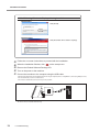
Displaying or Exiting VPanel
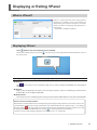
What is VPanel?
VPanel is an application that allows milling machine
operation on a computer screen. It has functions to
output milling data, perform maintenance, and make
various corrections. It also displays milling machine error messages.
"Setup Guide" ("Installing the Software")
Displaying VPanel
Click
(VPanel icon) in the task tray on the desktop.
VPanel will be displayed. If you cannot find
the [Start] menu).
in the task tray, start the program from the Windows [Start] screen (or
Starting from the Windows [Start] screen (or [Start] menu)
Windows 8.1
on the [Start] screen, and from the Apps screen, click the [VPanel for DWX-4W] icon under [Roland
Click
DWX-4W].
Windows 8
Right-click the background in the [Start] screen to display the app bar, and then click [All Apps]. Click the [VPanel
for DWX-4W] icon under [Roland DWX-4W].
Windows Vista/7
From the [Start] menu, click [All Programs] (or [Program]), then [Roland DWX-4W]. Then click [VPanel for DWX-4W].
VPanel serves as resident software.
VPanel works as resident software that is constantly working to manage the milling machine, send e-mails*, and so on. It is
recommended to configure the settings so that VPanel starts automatically when the computer starts. (P. 8 ""Settings"
Tab") Also, clicking
in the upper right corner of the window will cause the window to disappear from the screen, but
the program will not be exited. While VPanel is running,
is constantly displayed in the task tray.
* E-mails are sent to notify of milling completion or errors that occur. (P. 10 ""Mail" Tab")
1. Operation Screen
5
Displaying or Exiting VPanel
VPanel Display in the Task Tray
When the VPanel icon is displayed in the task tray, the status of a connected milling machine is always monitored. The display
of the VPanel icon changes depending on the status of the milling machine. The meanings of the displays are shown below.
Indicates that at least one of the connected milling machines is on (is online). Messages are
displayed automatically if an error occurs, during milling, and in similar situations.
Even after the message disappears, if you hover the mouse pointer over this icon, the status
of each connected machine (such as Ready, Milling, Finished, Completed, or Offline) will be
displayed.
Messages prompting you to perform maintenance (such as "Spindle run-in (long) required")
will also be displayed. In these situations, perform the maintenance work indicated by the
message.
P. 23 "STEP 0: Spindle Run-In (Short)", P. 32 "3. Maintenance"
Indicates that all the connected milling machines are off.
Indicates that an error has occurred on at least one of the connected milling machines.
If you hover the mouse pointer over this icon, you can check which machine has the error.
Exiting VPanel
Right-click on
6
in the task tray and click [Exit].
1. Operation Screen
VPanel Window
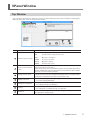
Top Window
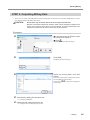
This is the VPanel top window. It displays the statuses of connected milling machines and an output list of milling data.
Output of milling data can also be executed in this window.
No.
Displayed content
Machine operation status
Details
READY:
Milling data can be received.
OFF:
The power of the milling machine is off.
BUSY:
Operation is in progress.
ERROR:
An error has occurred.
PAUSE:
Operation is paused.
COVER:
The front cover is open.
Name of connected machine
Displays the ID and name of a connected machine. The IDs of machines with the
power turned off are shown with [-].
If you click the name of a connected milling machine, the status light of the milling
machine will flash. This enables you to check the connected machines when multiple
machines are connected to the computer.
Milling machine status
Displays the operation status, spindle speed, milling time, etc. The information displayed
is for the machine that has the radio button to the left of the name selected (the machine
for which the round button to the left of its name displays a dot).
Output a file/cancel
Milling bur management
Settings
Output list
Used when outputting or cancelling milling data.
P. 25 "STEP 2: Outputting Milling Data"
Used to select or register a milling bur for which you want to control the work time.
P. 12 ""Milling bur management" Dialog Box"
Display the settings window.
P. 8 ""Settings" Tab", P. 9 ""Maintenance" Tab", P. 10 ""Mail" Tab"
Displays the data being milled and the data awaiting processing.
Also displays the milling progress.
1. Operation Screen
7
VPanel Window
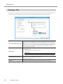
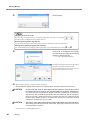
"Settings" Tab
In this tab, you can configure the VPanel auto-startup settings, settings related to the NC code, and other settings. When more
than one machine is connected, the machine selected in the top window becomes the target for the settings.
Click to display the special
website in your Internet
browser.
NC code with decimal point
Select the handling and interpretation of the decimal point in NC codes. With "Conventional," the unit is interpreted as millimeter (or inch) when there is a decimal
point, and as 1/1000 millimeter (or 1/10000 inch) when there is no decimal point.
With "Calculator," the unit is always interpreted as millimeter (or inch) regardless of
whether there is a decimal point. Select the scope of the application when selecting
"Calculator." Select an appropriate setting according to your CAM or NC code.
Initial setting: Conventional
You can set an ID to a machine. This is useful when connecting multiple units.
Initial setting: A
"Setup Guide" ("Connecting Multiple Units")
Machine ID
Important
To change an ID, be sure to follow the procedure explained in the "Setup Guide."
8
Run VPanel at PC start-up
When this is checked, VPanel will start automatically when Windows starts up and
the VPanel icon will be displayed in the task tray.
Initial setting: Checked
Version
Displays the VPanel version and the firmware of connected machines (the machine
selected in the top window when more than one machine is connected).
1. Operation Screen
VPanel Window
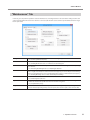
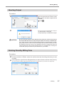
"Maintenance" Tab
In this tab, you can perform operations related to maintenance, including automatic correction of the milling machine and
system reporting. When more than one machine is connected, the machine selected in the top window becomes the target
for the operations.
Daily maintenance
Perform collet and spindle maintenance before starting daily operations.
P. 23 "STEP 0: Spindle Run-In (Short)"
Correction
Perform corrections to correct the rotary axis position. You can usually use "Automatic correction."
P. 39 "Milling Machine Correction", P. 11 ""Manual correction" Dialog Box"
Move
Move the spindle unit and rotary axis. This function is used for cleaning and when repacking
the machine.
P. 34 "Cleaning after Milling Finishes", P. 59 "Attaching the Retainers"
ATC
Perform operation tests, maintenance, and other tasks that use the ATC magazine. If the milling
bur is caught on the workpiece and the machine has stopped, you can forcibly release the milling
bur by clicking [Emergency release] (enabled when the power is on with the front cover open).
P. 45 "Milling Bur Change Test", P. 36 "Care of the Dummy Pin for Milling"
Coolant
Use this function to reset the coolant work time and to drain all of the coolant inside the machine.
P. 55 "Draining the Coolant Lines"
Spindle
Displays the total work time of the spindle and can be used for long-term spindle management
such as run-in when the spindle has not been used for a long time.
P. 57 "Spindle Run-In (Long)"
Report
You can use these buttons to create reports such as machine system reports (including firmware
version and total operating hours) and error reports. The various reports can be saved as files.
1. Operation Screen
9
VPanel Window
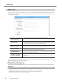
"Mail" Tab
In this tab, you can configure the settings so that you receive a notification e-mail when milling has finished, when an error
has occurred, or when maintenance has finished. When more than one machine is connected, all of the machines become
the targets for the settings.
Check [Use mail notification] to enter each item. For information on the input fields, see the table below.
Receiver address
The recipient's e-mail address. You can input more than one address by separating
with a comma.
Sender address
The e-mail address used for the computer that is currently used to configure VPanel
settings. (This becomes the sender's e-mail address. The address must be one that
can send e-mails via the outgoing server mentioned below.)
Server host name
The outgoing e-mail server name (SMTP server name) of the e-mail software used
on the computer that is currently used to configure VPanel settings.
Server port number
The outgoing e-mail server port number of the e-mail software used on the computer that is currently used to configure VPanel settings.
Use SSL connection
Check to use a security-protected connection (SSL). Configure the settings according to the e-mail software being used.
Use SMTP authentication
User name / Password
Check to use authentication when sending e-mails. Input the user name and password for authentication. Configure the settings according to the e-mail software
being used.
Click [Send test] to perform a sending test. If an e-mail with the following data is received at the address specified in "Receiver
address," configuration of the settings is complete.
Subject: <Machine name> Body: Test
If the e-mail fails to send, the "Windows Script Host" error window will be displayed. Check the content in the input fields again.
Important
* It may be impossible to send e-mails because of security software settings or the like. If e-mails cannot be sent, check the
settings of the security software being used as anti-virus software or for a similar purpose.
* For detailed information about the e-mail settings, consult your network administrator.
* VPanel does not support TLS connections (STARTTLS).
10
1. Operation Screen
VPanel Window
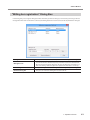
"Manual correction" Dialog Box
In this dialog box, you can directly enter the manual correction values of the milling machine. Perform correction to precisely
adjust accuracy. When more than one machine is connected, the machine selected in the top window becomes the target
for correction.
* Perform automatic correction before performing this correction.
P. 39 "Milling Machine Correction"
Distance
Correct moving distances in the X, Y, and Z directions. Set the correction value
while considering the initial moving distance as 100%.
Initial setting: 100%
A axis back side
Correct the angle when the A axis is rotated 180 degrees. Set the correction
value while considering the initial setting as 0.00 degrees.
Initial setting: 0.00 degrees
Origin point
Correct the origins of the X, Y, and Z axes. Set the correction value while considering the initial setting as 0.00 mm.
Initial setting: 0.00 mm
Clear these values when executing
the automatic correction
Check to reset the values for "Distance," "Origin point," and "A axis back side"
when performing automatic correction.
Initial setting: Checked
1. Operation Screen
11
VPanel Window
"Milling bur management" Dialog Box
By selecting a milling bur to be used in this dialog box, the work time of the selected milling bur will be recorded automatically. In addition, when the bur reaches the preset replacement time, a warning message will be displayed. When more
than one machine is connected, the machine selected in the top window is managed.
12
Milling burs
Here you can select from among the registered milling burs the bur whose work time you
want to count. (#1 to #4 are stocker numbers.)
Select a milling bur according to the milling burs set in the ATC magazine. The name and
work time / replacement time of the selected milling bur will be displayed on the top
window.
When not using this function, leave the box blank.
Work time /
Replacement time
Displays the work time and replacement time of the selected milling bur. The replacement
time can be changed from "Milling bur registration." After replacing the milling bur with a
new one, click [Reset] to set the work time to 0.
Milling bur registration
Here you can register milling burs whose work time you want to manage, or remove burs
you no longer want to manage. Click here to open the "Milling bur registration" dialog box.
1. Operation Screen
P. 13 ""Milling bur registration" Dialog Box"
VPanel Window
"Milling bur registration" Dialog Box
In this dialog box, you can register milling burs whose work time you want to manage, or remove burs you no longer want to
manage. When more than one machine is connected, the milling burs for the machine selected in the top window are managed.
Milling bur list
Displays the name, work time, and replacement time of a registered milling bur.
Milling bur info
Allows the milling bur name, work time, and replacement time of the milling bur selected in the list to be edited. Click [Save] to overwrite and save the edited content.
Because replacement times depend on the type of milling bur or workpiece as
well as the milling conditions, adjust the replacement time value as necessary.
Add milling bur
Here you can register additional milling burs. You can register up to 20 milling burs.
Remove milling bur
Here you can remove the milling bur selected in the list.
1. Operation Screen
13
2. Milling
Using/Reading the Built-In Panel.........................................15
Using/Reading the Built-In Panel................................................ 15
Statuses Indicated by Status Light Color.................................... 15
Switching the Power On or Off.............................................16
Switching the Power On............................................................. 16
Switching the Power Off............................................................. 16
Preparing for Milling.............................................................17
Preparing a Workpiece (Usable Workpieces)............................. 17
Preparing a Milling Bur............................................................... 17
Preparing Compressed Air (Setting the Regulator).................... 17
Filling the Coolant Tank/Replacing the Coolant.......................... 18
Starting Milling......................................................................23
Milling Precautions...................................................................... 23
STEP 0: Spindle Run-In (Short).................................................. 23
STEP 1: Mounting the Workpiece............................................... 24
STEP 2: Outputting Milling Data................................................. 25
Aborting Output........................................................................... 27
Deleting Standby Milling Data.................................................... 27
Following Daily Operations..................................................28
Collet Maintenance..................................................................... 28
14
Using/Reading the Built-In Panel
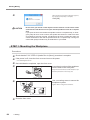
Using/Reading the Built-In Panel
POWER
This lights up when the power is turned on.
PAUSE
Illuminates when operation is paused. Flashes when operation is ongoing (from the point when
the operation button is pressed during milling to the point when operation is paused).
ERROR
Flashes when an error has occurred.
CANCEL
Flashes when data is being cancelled and during initialization.
Milling data received while this light is flashing will be cancelled.
Operation button
Pressing this button during milling will pause or restart the machine.
Pressing and holding this button during milling will abort milling or clear some errors.
Pressing this button in standby will rotate the rotary axis position 180 degrees.
The button will flash during initialization, spindle head or rotary axis operation, spindle rotation, and
maintenance operation. The button will illuminate under any other status while the power is on.
Statuses Indicated by Status Light Color
Status light
Blue
Initialization is in progress or the machine is in the standby status. (In the standby status, the color will
change to white when the front cover is opened.)
In the standby status, if no operation is initiated within 5 minutes, the machine will change to the sleep
status, and the status light will turn off.
White
Milling is in operation or is paused. Also, in the standby status, white light will illuminate when the front
cover is opened.
Yellow
When lit yellow, an error has occurred, and the machine has been paused.
Check the error details shown on VPanel. Press the operation button on the built-in panel to resume milling.
Red
When lit or flashing red, an error has occurred and milling has been stopped. Milling cannot be resumed.
Check the error details shown on VPanel. When illuminated, pressing and holding the operation button on
the built-in panel will cancel milling and return the machine to the ready status. When flashing, turn off the
power once and start up the machine again.
Off
The machine is sleeping or the power has been turned off and all lights are out.
2. Milling
15
Switching the Power On or Off
Switching the Power On
Procedure
Close the front cover.
Hold this with
both hands.
Switch on the machine's power switch.
The machine starts initialization. When the
status light stops flashing and remains steadily
lit, initialization is complete.
Switching the Power Off
Procedure
Switch off the machine's power switch.
16
2. Milling
Preparing for Milling
Preparing a Workpiece (Usable Workpieces)
Workpiece Materials
Glass ceramics
Composite resins
Types and Sizes of Workpieces
Type: Type with pin
Maximum number of mountable workpieces: 3
Maximum size of mountable workpieces: 40 (W) × 20 (D) × 20 (H) mm
* However, the workpiece size is limited by the number of workpieces mounted in the machine,
and the number of mountable workpieces is limited by the size of the workpieces mounted in the machine.
Preparing a Milling Bur
Usable Milling Burs
Dedicated milling bur (3 types)
Setting Milling Burs in the ATC Magazine
Set the milling burs in stockers #1 to #4 of the ATC magazine. Set the different types of milling burs in the stocker numbers
according to the milling data settings.
Ensure that the tips of the burs face down. Exercise caution regarding the orientation of the burs.
Preparing Compressed Air (Setting the Regulator)
Recommended Set Pressure
0.6 MPa to 0.8 MPa
2. Milling
17
Preparing for Milling
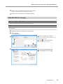
Filling the Coolant Tank/Replacing the Coolant
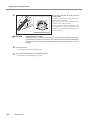
CAUTION
Do not overfill or tilt the coolant tank.
CAUTION
When raising or lowering the coolant tank,
hold the positions indicated in the following figure.
The fluid inlet on the coolant tank is open. Overfilling or tilting will cause fluid to
spill out.
Failing to do so may result in your fingers being pinched,
leading to injury.
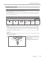
Situations Requiring This Work
Filling: When first using the machine. / When the fluid level in the tank reaches the lower limit.
Lower
limit
Replacement: Once a week, or when the work time exceeds 15 hours.
When the work time exceeds 15 hours, the message shown above is displayed, prompting coolant replacement.
Click [OK], and follow the procedure below to replace the coolant.
If the message appears during milling, click [OK], and replace the coolant as usual after milling completes.
If replacement will be performed before the work time exceeds 15 hours, follow the same procedure for replacing
the coolant.
Water to Use
Use soft or purified water. Using hard water may have a negative effect on the service life of the milling bur and on the quality
of the product.
18
2. Milling
Preparing for Milling
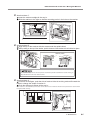
Filling the Coolant Tank/Replacing the Coolant
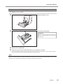
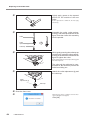
1. Replace the coolant.
Open the bottom cover.
Pull out the coolant tank.
Important
Move the coolant tank slowly. Forcefully moving the coolant tank may cause the coolant
to spray out.
Remove the coolant tank.
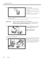
Clean the inside of the coolant tank before you replace the coolant.
Pour a little tap water into the tank, and then shake the tank to the left and right. Dispose of any dirty water. Repeat
this step until the water does not become dirty when you shake the tank.
Note
Dispose of coolant properly, in accordance with the laws in effect in your locale. Do not recklessly dispose of it in sewer
systems, rivers, or streams. Doing so may have an adverse impact on the environment.
2. Milling
19
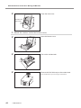
Preparing for Milling
Make the coolant.
The coolant should have a water-to-additive
ratio of 95:5. Use the included measuring cup for
measuring.
The capacity of the coolant tank is approximately
3 L. To fill the tank, use 2850 mL of water and 150
mL of additive.
After you combine the water and additive, there is
no need to mix the substances together.
Refer to the appropriate safety data sheet (SDS) for the chemical substances used in the additives and the safety
related to those substances.
Contact your authorized Roland DG Corporation dealer to purchase additives.
CAUTION
Be sure to put the specified additive in the coolant tank.
Additives are effective in reducing coolant deterioration and raising the milling
efficiency in order to maintain product performance. Also, if additives are not
used, the coolant may generate an unpleasant odor.
Remove the fluid inlet cap on the coolant tank, and pour in the coolant.
Do not add coolant past MAX.
After filling with coolant,
close the fluid inlet cap.
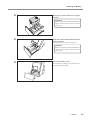
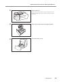
2. Store the coolant tank.
Wipe the inside of the bottom cover.
Water accumulates in the bottom inside the bottom cover after using for long periods. Wipe regularly at the same timing as coolant replacement.
Also, pull the rail forward when cleaning.
Part to be wiped
20
2. Milling
Preparing for Milling
Return the coolant tank to its original
position.
Important
Move the coolant tank slowly. Forcefully moving the coolant tank may cause the coolant
to spray out.
Push the coolant tank toward the back
of the machine.
Push until you feel the tank click into place.
Important
Move the coolant tank slowly. Forcefully moving the coolant tank may cause the coolant
to spray out.
Close the bottom cover.
This completes the filling of the coolant tank or
the replacing of the coolant.
2. Milling
21
Preparing for Milling
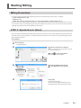
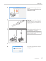
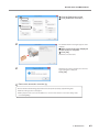
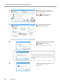
3. Reset the coolant work time.
After replacing the coolant, perform the following procedure.
If the work time is not reset, the message prompting coolant replacement will continue to be displayed.
Show VPanel.
P. 5 "Displaying VPanel"
Select a machine to operate.
Click the radio button to the left of the name of
the machine to operate.
Click
in the top window.
The [Settings] screen will appear.
22
Click the [Maintenance] tab.
Click [Reset].
Click [OK].
The coolant work time display will become "0."
The replacement operation is now complete.
2. Milling
Starting Milling
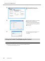
Milling Precautions
Do not turn the power off during the following operations or stop work before the operation is complete.
Collet maintenance (P. 28)
Milling (P. 25)
When the machine is operating after you click the [Emergency release] button (P. 9)
If you turn the power off during these operations or stop work before the operation is complete, the spindle unit may be
in a state where it does not hold anything (the milling bur and detection pin may also be in states where they do not hold
anything). Note that the machine may malfunction in this state.
STEP 0: Spindle Run-In (Short)
Be sure to perform the following tasks before daily operations. These tasks are necessary for maintaining a favorable machine
condition and for ensuring a high level of product quality. If these tasks are not executed, a message prompting operation
will be displayed in VPanel.
Procedure
Show VPanel.
P. 5 "Displaying VPanel"
Select a machine to operate.
Click the radio button to the left of the name of
the machine to operate.
Click
in the top window.
The [Settings] screen will appear.
Click the [Maintenance] tab.
Click [Spindle run-in (short)].
Click [OK].
Spindle run-in will begin.
The machine status light will flash blue. The remaining work time will be displayed on VPanel.
2. Milling
23
Starting Milling
When the message shown in the figure appears,
the spindle run-in (short) is complete.
Click [OK].
CAUTION
Do not insert your hands or other objects into the machine or look into the inside
of the machine with the front cover open until the spindle has come to a complete
stop.
If you open the front cover before the spindle comes to a complete stop, an emergency stop will occur. Due to inertia, the spindle will continue to rotate even after
an emergency stop has occurred. It is dangerous to touch a rotating tool. Also, the
coolant continues to flow until the spindle comes to a complete stop. Coming into
contact with sprayed coolant may be hazardous to your health.
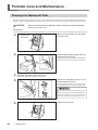
STEP 1: Mounting the Workpiece
Procedure
Check that the P. 23 "STEP 0: Spindle Run-In (Short)" procedure is complete.
Once initialization completes, open the front cover.
If the power is off, close the front cover and turn on the power.
P. 16 "Switching the Power On"
Insert the pin portion of the workpiece
into the hole on the rotary axis.
Align the notch on the base of the workpiece pin
with the protrusion on the rotary axis.
Use a mounting screw to secure the
workpiece in place.
Tighten with a hexagonal screwdriver.
OK
24
Close the front cover.
2. Milling
Not OK
Starting Milling
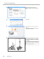
STEP 2: Outputting Milling Data
* You can also use commercial CAM software to output milling data. For information on compatible CAM software, contact
your authorized Roland DG Corporation dealer.
CAUTION
Do not place any electronic devices in the vicinity of this machine.
Because coolant flows within this machine, water may be sprayed on objects in the
vicinity of the machine when its front cover is opened. To prevent malfunctions, do
not place any electronic devices in the vicinity of this machine.
Procedure
In the top window of VPanel, select
the machine to output to.
Click
.
The [Output a file] window will appear.
Click [Add].
Select the milling data, and click
[Open].
The [Open] window will appear.
The selected milling data is displayed in the data
list of the [Output a file] window.
Repeat steps
to output the milling data
continuously.
Verify that the milling bur has been set.
Check that the coolant has been set.
P. 17 "Preparing a Milling Bur"
P. 18 "Filling the Coolant Tank/Replacing the Coolant"
2. Milling
25
Starting Milling
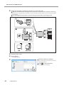
Click [Output].
Changing the data list order
You can change the output order by selecting the milling data in the data list and clicking
(The milling data is output from the top of the data list.)
or
.
Removing milling data in the data list
You can remove milling data in the data list by selecting the milling data and clicking "Remove."
Adding milling data by dragging and dropping
You can add milling data by dragging and dropping data on the window displayed in steps
and .
Verify that a workpiece and milling
bur have been mounted on the milling
machine, and click [OK].
P. 24 "STEP 1: Mounting the Workpiece"
The output milling data is displayed in the output
list of the top window, and milling starts.
The estimated milling time and a progress bar are
displayed next to the machine name.
When milling is finished, a completion buzzer will sound.
Check that the spindle has come to a complete stop, and then open the front cover.
CAUTION
Do not insert your hands or other objects into the machine or look into the inside of
the machine with the front cover open until the spindle has come to a complete stop.
If you open the front cover before the spindle comes to a complete stop, an emergency
stop will occur. Due to inertia, the spindle will continue to rotate even after an emergency
stop has occurred. It is dangerous to touch a rotating tool. Also, the coolant continues
to flow until the spindle comes to a complete stop. Coming into contact with sprayed
coolant may be hazardous to your health.
CAUTION
After milling, thoroughly wash the products with purified water or a similar substance.
After milling, there will be coolant on the product. Using the product as is may cause
an inflammation or the like.
Continue on to P. 28 "Following Daily Operations".
26
2. Milling
Starting Milling
Aborting Output
Procedure
In the top window of VPanel, select
the machine for which output will be
aborted.
Click
.
The message shown in the figure will be displayed.
To abort output, click [OK].
Click [Cancel] to not abort the output.
CAUTION
Do not insert your hands or other objects into the machine or look into the inside of
the machine with the front cover open until the spindle has come to a complete stop.
If you open the front cover before the spindle comes to a complete stop, an emergency stop will occur. Due to inertia, the spindle will continue to rotate even after
an emergency stop has occurred. It is dangerous to touch a rotating tool. Also, the
coolant continues to flow until the spindle comes to a complete stop. Coming into
contact with sprayed coolant may be hazardous to your health.
Deleting Standby Milling Data
Procedure
In the top window of VPanel, select the machine that has the milling data that you want
to delete.
In the output list, right-click the milling data that you want to delete, and then click [Cancel].
You can only delete standby milling data (milling data that is second from the top or lower in the output list).
2. Milling
27
Following Daily Operations
Collet Maintenance
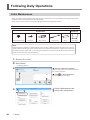
Be sure to perform the following tasks after daily operations. These tasks are necessary for maintaining a favorable machine
condition and for ensuring a high level of product quality.
If these tasks are not executed, a message prompting operation will be displayed in VPanel.
Required Tools
Commercially
available item
Included items
Collet replacement jig
Collet tap
Taper cleaner
Collet brush
Grease
Dry cloth
Note
Collet maintenance should be completed quickly. This is because a sufficient amount of compressed air must be
supplied while performing the work, and if the work is not completed promptly, the compressed air supply will
be insufficient. If the compressed air can no longer be supplied, an error will occur, which will result in the need
to start the operation over from the beginning.
1. Remove the collet.
Show VPanel.
P. 5 "Displaying VPanel"
Select a machine to operate.
Click the radio button to the left of the name of
the machine to operate.
Click
in the top window.
The [Settings] screen will appear.
28
2. Milling
Click the [Maintenance] tab.
Click [Collet maintenance].
Following Daily Operations
If a workpiece or the automatic
correction jig is attached:
Remove the workpiece or the automatic
correction jig, close the front cover, and
then click [OK].
If no workpiece or automatic
correction jig is attached:
Click [OK].
The window shown in the figure
appears automatically.
Open the front cover.
Hold this with
both hands.
Press the collet replacement jig
against the collet, and then insert
the collet tap.
Align the hexagonal tip of the collet and the
hexagonal portion of the collet replacement jig.
Important
Collet
replacement jig
Collet tap
Rotate the collet replacement jig while the
collet tap is inserted. If the collet replacement
jig is rotated without the collet tap inserted,
the collet may be damaged.
While gently pressing the collet tap up
into the hole, rotate the collet replacement
jig in the direction indicated in the figure.
Rotate the collet replacement jig until the collet
naturally comes free.
Due to the pressure of the compressed
air, the collet may be forcefully pushed
out when it comes free. Gently support
the collet with your hand so that the
collet does not fall out.
2. Milling
29
Following Daily Operations
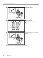
2. Clean the inside of the spindle and the collet.
Clean the inside of the spindle (where
contact with the collet is made) with
the taper cleaner.
Rotate the taper cleaner left and right as if you are
brushing the inner portion of the spindle.
Wipe the outer portion of the collet with
a clean, dry cloth.
Do not hold the tapered portion tightly. This part
being deformed may result in malfunctions.
Clean the inner portion of the collet
with the collet brush.
Rotate the collet brush left and right as if you are
brushing the inner portion of the collet.
Lightly apply grease to the tapered
portion on the outside of the collet.
A thin application is sufficient. Do not apply
excessively.
Collet
Collet
replacement jig
Collet tap
30
2. Milling
Assemble the collet, collet replacement
jig, and collet tap as shown in the figure,
and then insert this assembly into the
spindle.
Following Daily Operations
While gently pressing the collet tap up into
the hole, rotate the collet replacement jig
in the direction indicated in the figure to
tighten the collet.
Keep rotating until the collet replacement jig will
not rotate any more.
The collet will be subjected to compressed air. Be careful to prevent the
collet from falling out.
Attach the collet replacement jig and
the collet tap.
Collet
replacement jig
Collet tap
Close the front cover.
Hold this with
both hands.
When the message shown in the figure appears,
the collet maintenance is complete.
Click [OK].
2. Milling
31
3. Maintenance
Maintenance Precautions.....................................................33
Maintenance Precautions........................................................... 33
Daily Care.............................................................................34
Cleaning after Milling Finishes.................................................... 34
Care of the Dummy Pin for Milling.............................................. 36
Periodic Care and Maintenance ..........................................38
Cleaning the Waterproof Plate.................................................... 38
Milling Machine Correction......................................................... 39
Milling Bur Change Test.............................................................. 45
Filling the Coolant Tank/Replacing the Coolant.......................... 46
Care and Storage of the Automatic Correction Jig..................... 47
Care of the Regulator Bowl........................................................ 47
Replacing Consumable Parts...............................................49
Replacing the Spindle Unit......................................................... 49
Milling Bur Service Life............................................................... 49
Replacing the Coolant Tank Filter............................................... 49
Replacing the Collet................................................................... 53
Extended Periods of Non-Use / Moving the Machine.......... 55
Draining the Coolant Lines......................................................... 55
Spindle Run-In (Long)................................................................ 57
Attaching the Retainers.............................................................. 59
32
Maintenance Precautions
Maintenance Precautions
WARNING
Never use a pneumatic blower.
WARNING
Never use a solvent such as gasoline, alcohol, or thinner to perform cleaning.
WARNING
Caution: High temperatures.
CAUTION
Be careful around the milling tool.
CAUTION
Use a dry cloth when cleaning silicone resin parts, and be careful to prevent the
silicone resin from being damaged.
This machine is not compatible with a pneumatic blower. Milling waste may get
inside the machine and cause fire or electrical shock.
Doing so may cause a fire.
The milling tool and spindle motor become hot. Exercise caution to avoid fire or burns.
The milling tool is sharp. Broken milling tools are also dangerous. To avoid injury,
exercise caution.
The silicone resin being damaged may lead to electric leakage.
This machine is a precision device. Carry out daily care and maintenance.
Carefully wipe away any fluid or milling waste. Operating the machine with fluid or milling waste present may cause
malfunction or breakdown.
Never install in an environment where silicone substances (oil, grease, spray, etc.) are present. Doing so may cause
poor switch contact.
Do not turn the power off during the following operations or stop work before the operation is complete.
Automatic correction (P. 39)
Milling bur change test (P. 45)
Detection pin maintenance (P. 36)
When the machine is operating after you click the [Emergency release] button (P. 9)
If you turn the power off during these operations or stop work before the operation is complete, the spindle unit may be
in a state where it does not hold anything (the milling bur and detection pin may also be in states where they do not hold
anything). Note that the machine may malfunction in this state.
3. Maintenance
33
Daily Care
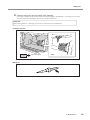
Cleaning after Milling Finishes
After milling finishes, clean inside the machine with a dry cloth. Carefully wipe around the spindle head and the rotary axis
parts shown in the following figure as fluid and milling waste in these areas may affect milling results.
CAUTION
Use a dry cloth to clean the inside of the equipment.
CAUTION
Be careful of the pointed portion inside the front cover.
Failure to do so may cause the components inside the equipment to degrade,
which can lead to injury.
There is a pointed portion inside the front cover. Exercise caution when cleaning.
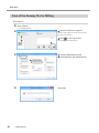
Procedure
Show VPanel.
P. 5 "Displaying VPanel"
Select a machine to operate.
Click the radio button to the left of the name of
the machine to operate.
Click
in the top window.
The [Settings] screen will appear.
34
3. Maintenance
Click the [Maintenance] tab.
Click [Default <-> Cleaning].
Daily Care
Clean the milling bur and the inside of the machine.
In particular, carefully clean the portions shown in the following figures. Click [Default <-> Cleaning] as necessary for
each cleaning location. Clicking this will cause the spindle head to move.
Important
When clicking [Default <-> Cleaning], it's necessary to close the front cover beforehand.
Inside the machine
Part to be wiped
Milling bur
3. Maintenance
35
Daily Care
Care of the Dummy Pin for Milling
Procedure
Show VPanel.
P. 5 "Displaying VPanel"
Select a machine to operate.
Click the radio button to the left of the name of
the machine to operate.
Click
in the top window.
The [Settings] screen will appear.
36
3. Maintenance
Click the [Maintenance] tab.
Click [Detection pin maintenance].
Click [OK].
Daily Care
The window shown in the figure appears automatically.
Open the front cover and remove the
dummy pin for milling.
Wipe the dummy pin for milling with
a dry cloth.
Any fluid or milling waste not wiped off will have
an effect on the milling results. Carefully wipe the
entire area clean.
Return the dummy pin for milling to the
ATC magazine's "D" stocker.
The detection pin should be oriented with the
tapered end up. Be careful not to confuse which
side is up and which is down.
Close the front cover.
The operation is complete once the message in
the figure is displayed.
Click [OK].
3. Maintenance
37
Periodic Care and Maintenance
Cleaning the Waterproof Plate
Through use, the waterproof plate attached on the inside of the front cover will become dirty and visibility from the outside will
drop. By cleaning the waterproof plate regularly, visibility can be maintained, making it easy to check the status of operations.
CAUTION
Never use a solvent such as gasoline, alcohol, or thinner to perform cleaning.
Doing so may cause a fire.
Procedure
Hold this with
both hands.
Make sure the power is off, and open
the front cover.
Remove the waterproof plate from the
inside of the front cover.
Slide the waterproof plate up, and remove it from
the protrusions on the front cover in 2 locations.
Wash the waterproof plate with water.
After washing, wipe off any moister on the plate.
Attach the waterproof plate on the
inside of the front cover.
Make sure that the protrusions on the front cover
are seated firmly in the 2 locations on the plate.
The waterproof plate has a top, bottom, front, and
back side. Be careful of the orientation when installing. If the orientation is not correct, the plate may
interfere with opening and closing the front cover.
38
3. Maintenance
Close the front cover.
Periodic Care and Maintenance
Milling Machine Correction
The accuracy of the milling machine may vary if it is used for a long period of time or the surrounding environment changes.
Performing automatic correction will correct the rotary axis position.
Situations Requiring This Work
When replacing the spindle unit
When the milling position is misaligned
When symptoms such as a line of level difference or a hole in the Z direction occurs in the milling results
This procedure must be performed by a trained service technician in the following cases.
When installing the machine in a different location
This work is required not only when installing the machine but also when moving the machine to a different location.
Contact your authorized Roland DG Corporation dealer to perform such work.
Required Tools
Included items
Automatic
correction jig
Detection pin for
correction
Commercially available item
Dry cloth
Make sure to keep the dummy pin for milling and the detection pin for correction
separate and to never mistake which is for milling and which is for correction.
If a detection pin is used for milling even once, it cannot be used to provide proper correction. If for
some reason a detection pin for correction is used for milling, a new detection pin for correction will
be necessary. In such cases, contact your authorized Roland DG Corporation dealer.
1. Replace the dummy pin for milling with the detection pin for correction.
Show VPanel.
P. 5 "Displaying VPanel"
Select a machine to operate.
Click the radio button to the left of the name of
the machine to operate.
Click
in the top window.
The [Settings] screen will appear.
3. Maintenance
39
Periodic Care and Maintenance
Click the [Maintenance] tab.
Click [Detection pin maintenance].
Click [OK].
The window shown in the figure appears automatically.
Open the front cover and remove the
dummy pin for milling.
Return the detection pin for correction
to the ATC magazine's "D" stocker
and install the dummy pin for milling
in its place.
The detection pin should be oriented with the
tapered end up. Be careful not to confuse which
side is up and which is down.
40
3. Maintenance
Periodic Care and Maintenance
Close the front cover.
If the message shown in the following
figure appears, click [OK].
Wipe the removed dummy pin for milling with a dry cloth.
Any fluid or milling waste not wiped off will have an effect on the milling results. Carefully wipe the entire area clean.
2. Perform automatic correction of the milling machine.
Open the front cover.
Hold this with
both hands.
Use a dry cloth to cleanly wipe away any fluid or dirt in the locations shown in the following figure.
If any fluid or dirt is present in these locations, correction might not occur properly.
Milling bur sensor
(contact side of the milling bur)
Detection pin for correction
and spindle head
Automatic correction jig
Part to be wiped
3. Maintenance
41
Periodic Care and Maintenance
Attach the automatic correction jig to hole "2" on the rotary axis.
Align the recessed portion of the jig with the protrusion on the rotary axis, and then insert the jig.
Ensure that there is no gap between the surfaces. It does not matter which of the two recesses on the jig is aligned
to the protrusion.
Use a hexagonal screwdriver to secure the jig in place with a mounting screw.
OK
Not OK
Close the front cover.
Show VPanel.
P. 5 "Displaying VPanel"
Select a machine to operate.
Click the radio button to the left of the name of
the machine to operate.
Click
in the top window.
The [Settings] screen will appear.
42
3. Maintenance
Periodic Care and Maintenance
Click the [Maintenance] tab.
Click [Automatic correction].
The window shown in the figure appears automatically.
Make sure that the work displayed
on the screen is complete.
Click [OK].
Automatic correction starts.
Automatic correction is complete once the message in the figure is displayed.
Click [OK].
Remove the automatic correction jig.
To check whether the following symptoms have been improved, actually output milling data.
When the milling position is misaligned
When symptoms such as a line of level difference or a hole in the Z direction occurs in the milling results
P. 23 "Starting Milling"
3. Maintenance
43
Periodic Care and Maintenance
3. Replace the detection pin for correction with the dummy pin for milling.
Show VPanel.
P. 5 "Displaying VPanel"
Select a machine to operate.
Click the radio button to the left of the name of
the machine to operate.
Click
in the top window.
The [Settings] screen will appear.
Click the [Maintenance] tab.
Click [Detection pin maintenance].
Click [OK].
The window shown in the figure appears automatically.
Open the front cover and remove the
detection pin for correction.
44
3. Maintenance
Periodic Care and Maintenance
Set the dummy pin for milling in the
ATC magazine's "D" stocker.
The detection pin should be oriented with the
tapered end up. Be careful not to confuse which
side is up and which is down.
Close the front cover.
If the message shown in the following
figure appears, click [OK].
Milling Bur Change Test
Check whether the milling bur has been set in the correct position at the correct length.
Procedure
Verify the milling bur is set in the ATC magazine.
Show VPanel.
P. 17 "Preparing a Milling Bur"
P. 5 "Displaying VPanel"
Select a machine to operate.
Click the radio button to the left of the name of
the machine to operate.
Click
in the top window.
The [Settings] screen will appear.
3. Maintenance
45
Periodic Care and Maintenance
Click the [Maintenance] tab.
Click [Milling bur change test].
Select which milling bur you want
to perform the change test for.
The numbers correspond to the ATC magazine
numbers. This test checks whether the milling bur
set to the selected number can be held correctly.
Click [OK].
When the message shown in the figure appears,
the milling bur change test is complete.
Click [OK].
Filling the Coolant Tank/Replacing the Coolant
Situations Requiring This Work
Filling: When the fluid level in the tank reaches the lower limit.
Replacement: Once a week, or when the work time exceeds 15 hours.
P. 18 "Filling the Coolant Tank/Replacing the Coolant"
46
3. Maintenance
Periodic Care and Maintenance
Care and Storage of the Automatic Correction Jig
The presence of rust, scratches, or grime on the automatic correction jig makes accurate detection impossible, which in turn
may make it impossible to perform milling as intended, and may even damage the machine.
Care and Storage
Before use, wipe clean using a dry, clean cloth, and make sure that no dust, rust, or scratches are found.
When the item will be out of use for a prolonged period, store in a location with low humidity and little fluctuation in
temperature.
Care of the Regulator Bowl
If the inside of the bowl becomes dirty, remove and wash the bowl.
Bowl
WARNING
Be sure to bleed off the air pressure before removing the regulator bowl.
WARNING
Clean the regulator bowl using a neutral detergent. Never use solvents such as
gasoline, alcohol, or thinner.
Failure to do so may result in a rupture or components flying off.
Using solvents may degrade the bowl and may result in a rupture.
Procedure
Stop the supply of compressed air.
Make sure that the pressure gauge reads "0."
3. Maintenance
47
Periodic Care and Maintenance
Remove the regulator.
Remove the screws at the locations shown in
the figure.
Remove the bowl.
Wash the bowl using a neutral detergent.
After making sure that the bowl is
completely dry, attach the bowl.
Loosen Tighten Loosen Tighten
48
Secure the regulator in its original
position.
Return the supply of compressed air to its previous state.
3. Maintenance
Replacing Consumable Parts
Replacing the Spindle Unit
Recommended Replacement Interval
When the total work time of the spindle exceeds 2,000 hours (with variation depending on the work situation).
The spindle unit is a part that wears out. You can use VPanel to view the total work time of the spindle. Refer to VPanel to determine when replacement is needed. Contact your authorized Roland DG Corporation dealer when it is time for replacement.
Milling Bur Service Life
Necessary Replacement Interval
Approx. 15 hours of work time
The work time for each milling bur can be viewed on VPanel.
P. 12 ""Milling bur management" Dialog Box"
The milling bur is a consumable part. Contact your authorized Roland DG Corporation dealer when it is time for replacement.
Replacing the Coolant Tank Filter
Contact your authorized Roland DG Corporation dealer to purchase new filters.
CAUTION
Do not overfill or tilt the coolant tank.
CAUTION
When raising or lowering the coolant tank,
hold the positions indicated in the following figure.
The fluid inlet on the coolant tank is open. Overfilling or tilting will cause fluid to
spill out.
Failing to do so may result in your fingers being pinched,
leading to injury.
Situations Requiring This Work
When the filter is dirty
Once a month (varies with work conditions)
Required Tools
Optional part
Filter
3. Maintenance
49
Replacing Consumable Parts
Cleaning
1. Clean the coolant tank.
Remove the coolant tank.
P. 18 "Filling the Coolant Tank/Replacing the Coolant"
Remove the fluid inlet cap on the coolant tank.
Discard the coolant.
Note
Dispose of coolant properly, in accordance with the laws in effect in your locale. Do not recklessly dispose of it in sewer
systems, rivers, or streams. Doing so may have an adverse impact on the environment.
Clean the inside of the coolant tank.
Pour a little tap water into the tank, and then shake the tank to the left and right. Dispose of any dirty water. Repeat
this step until the water does not become dirty when you shake the tank.
Important
Empty the coolant tank of as much fluid as possible before replacing the filter. The coolant tank is tilted when
replacing the filter, and it is easy for fluid remaining in the coolant tank to spill out in this situation.
2. Replace the coolant tank filter.
Remove the cap and filter.
Removing the filter cap allows for the filter to also
be removed. If the filter does not also come out,
pull it out from the hole.
Important
Fluid that has been absorbed into the filter
may spill out. We recommend that you place
a towel or some newspapers under the tank.
50
3. Maintenance
Replacing Consumable Parts
Remove the pipe from the center of
the filter.
Clean the pipe.
Attach the cap to a new filter.
Wash the pipe with water.
Important
Keep the cap aligned with the filter and insert straightly. If inserted at an angle or if the O-ring is
twisted, it will not be possible to obtain sufficient filtration.
O-ring
Not OK
Not OK
Insert the removed pipe into the center
of the new filter.
The pipe can be inserted in any direction.
3. Maintenance
51
Replacing Consumable Parts
Insert the new filter and cap into the
coolant tank.
Insert the new filter and cap through the hole on
the side of the coolant tank.
Align the hole on the side of the filter with the
protrusion at the back of the tank.
At the same time, align the indentation on the
filter cap with the protrusion on the tank. If the
alignment is not correct, the filter will not fall all
the way into place.
CAUTION
52
Handle the filter carefully.
Dropping the filter or grasping it too strongly may damage the filter. If the filtration
function does not work due to damage, the coolant line may be clogged with milling
waste, which may lead to coolant leaks and fire and electrical shock due to current
leakage.
Fill with coolant.
Return the coolant tank to its original position.
P. 18 "Filling the Coolant Tank/Replacing the Coolant"
P. 18 "Filling the Coolant Tank/Replacing the Coolant"
3. Maintenance
Replacing Consumable Parts
Replacing the Collet
Recommended Replacement Interval
When scratches or rust appears on the tapered portion of the collet
If the collet is deformed
The collet is a part that wears out. If a large force, such as an overload during milling, is applied to the collet, the collet may
have become deformed. In such cases, it is necessary to replace the collet. Contact your authorized Roland DG Corporation
dealer to purchase a replacement collet.
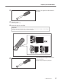
Required Tools
Commercially
available item
Included items
Collet replacement jig
Collet tap
Taper cleaner
Collet brush
Grease
Dry cloth
Note
Collet replacement should be completed quickly. This is because a sufficient amount of compressed air must be
supplied while performing the work, and if the work is not completed promptly, the compressed air supply will
be insufficient. If the compressed air can no longer be supplied, an error will occur, which will result in the need
to start the operation over from the beginning.
Procedure
Remove the old collet.
Refer to P. 28 "Collet Maintenance" to remove the old collet.
Clean the inside of the spindle (where
contact with the collet is made) with
the taper cleaner.
Rotate the taper cleaner left and right as if you are
brushing the inner portion of the spindle.
3. Maintenance
53
Replacing Consumable Parts
Lightly apply grease to the tapered
portion on the outside of the new
collet.
A thin application is sufficient. Do not apply
excessively.
Assemble the collet, collet replacement jig, and collet tap as shown in the
figure, and then insert this assembly
into the spindle.
Collet
Collet
replacement jig
Collet tap
While gently pressing the collet tap up
into the hole, rotate the collet replacement jig in the direction indicated in the
figure to tighten the collet.
Keep rotating until the collet replacement jig will
not rotate any more.
The collet will be subjected to compressed air. Be careful to prevent the
collet from falling out.
Attach the collet replacement jig and
the collet tap.
Collet
replacement jig
Collet tap
Close the front cover.
Replacing the collet is complete once the message in the figure is displayed.
Click [OK].
54
3. Maintenance
Extended Periods of Non-Use / Moving the Machine
Draining the Coolant Lines
Drain the fluid collected in the coolant lines running through the machine.
Situations Requiring This Work
When there are no plans to use the machine for 1 week or longer (or when the machine has not been used for 1 week
or longer)
Before moving the machine (especially when there is a risk of coolant spillage)
Required Tools
Commercially
available item
Tray
Draining
Procedure
If a workpiece or a milling bur is mounted on the machine, remove it.
Do not remove the detection pin.
Remove the coolant tank and discard the coolant.
Proceed to the next step without returning the coolant tank to its original position.
P. 18 "Filling the Coolant Tank/Replacing the Coolant"
Place the tray with the coolant tank
inside the bottom cover in the stored
position.
Important
Because some water may drip when draining
the pathways, keep the tray in place until the
coolant tank is returned to its original position.
Show VPanel.
P. 5 "Displaying VPanel"
3. Maintenance
55
Extended Periods of Non-Use / Moving the Machine
Select a machine to operate.
Click the radio button to the left of the name of
the machine to operate.
Click
in the top window.
The [Settings] screen will appear.
Click the [Maintenance] tab.
Click [Drain coolant].
Make sure that the work displayed
on the screen is complete.
Click [OK].
The coolant will begin to be discharged.
If the coolant tank has been attached, the message shown in
the figure to the left will be displayed. Remove the coolant
tank, click [OK], and then perform the procedure again from
step
.
Draining of the coolant lines is complete once the
message in the figure is displayed.
Click [OK].
56
3. Maintenance
Extended Periods of Non-Use / Moving the Machine
Remove the tray placed inside the bottom cover.
Return the coolant tank to its original position.
Dispose of any water that has accumulated in the tray.
Spindle Run-In (Long)
Situations Requiring This Work
When the machine has not been used for 1 month or longer
Performing Run-In
Procedure
Close the front cover and turn on the power.
Show VPanel.
P. 5 "Displaying VPanel"
Select a machine to operate.
Click the radio button to the left of the name of
the machine to operate.
Click
in the top window.
The [Settings] screen will appear.
Click the [Maintenance] tab.
Click [Spindle run-in (long)].
3. Maintenance
57
Extended Periods of Non-Use / Moving the Machine
If a workpiece or the automatic correction jig is attached:
Remove the workpiece or the automatic correction jig, close the front
cover, and then click [OK].
If no workpiece or automatic correction jig is attached:
Click [OK].
Open the front cover.
Spin the spindle around 10 times
in either direction by hand.
Close the front cover.
Spindle run-in will begin.
The machine status light will flash blue. The remaining work time will be displayed on VPanel.
When the message shown in the figure appears,
the spindle run-in (long) is complete.
Click [OK].
CAUTION
Do not insert your hands or other objects into the machine or look into the inside
of the machine with the front cover open until the spindle has come to a complete
stop.
If you open the front cover before the spindle comes to a complete stop, an emergency stop will occur. Due to inertia, the spindle will continue to rotate even after
an emergency stop has occurred. It is dangerous to touch a rotating tool. Also, the
coolant continues to flow until the spindle comes to a complete stop. Coming into
contact with sprayed coolant may be hazardous to your health.
58
3. Maintenance
Extended Periods of Non-Use / Moving the Machine
Attaching the Retainers
Situations Requiring This Work
When moving the machine
Attach the retainers to protect the machine from vibration during shipment.
Required Tools
Commercially
available item
Securing tape
Attaching the Retainers
Make sure to drain all coolant lines before installing the retainers.
P. 55 "Draining the Coolant Lines"
1. Move the position of the spindle head.
Close the front cover and turn on the power.
Show VPanel.
P. 5 "Displaying VPanel"
Select a machine to operate.
Click the radio button to the left of the name of
the machine to operate.
Click
in the top window.
The [Settings] screen will appear.
3. Maintenance
59
Extended Periods of Non-Use / Moving the Machine
Click the [Maintenance] tab.
Click [Packing].
The spindle will move.
When the message shown in the figure appears, movement of
the spindle will be complete.
Click [OK].
2. Attach the retainer inside the front cover.
Make sure the front cover is closed, and turn off the power.
Open the front cover.
Hold this with
both hands.
60
3. Maintenance
Remove the waterproof plate.
Extended Periods of Non-Use / Moving the Machine
Attach retainer C.
Insert the retainer straight all the way in.
Slide the retainer to the right so that the mounting part is in the hole on the retainer.
Attach retainer B.
Align the top of the retainer with the area around the spindle head.
While pushing on the top of the retainer, push the bottom of the retainer so that it slides into place.
Silicone portion
Be careful not to pinch the silicone portion around the spindle head with the retainer. Doing so
may weaken the secureness of the retainer.
Attach retainer A.
As shown in the figure, push the side of retainer A that is touching retainer B toward the
inside to change the shape of retainer A.
Push the deformed retainer all the way in.
If the retainer is not deformed, it will catch on the uneven area inside the machine and prevent the retainer from
being attached correctly.
3. Maintenance
61
Extended Periods of Non-Use / Moving the Machine
Close the front cover.
Hold this with
both hands.
3. Attach the retainer inside the bottom cover.
62
Open the bottom cover.
Pull out the coolant tank.
Remove the fluid inlet cap on the coolant tank.
3. Maintenance
Place the fluid inlet cap in the storage compartment.
Extended Periods of Non-Use / Moving the Machine
Attach retainer D.
Return the coolant tank to its original position.
Close the bottom cover.
Use tape to secure the retainer to the coolant tank. Commercially available tape can be used to secure the retainer
to the tank.
3. Maintenance
63
4. Troubleshooting
Machine Problems................................................................65
The Machine Does Not Run/Cannot Generate Output............... 65
The Operation Button Does Not Respond.................................. 65
VPanel Does Not Recognize the Machine................................. 65
No Data Is Being Output to the Machine, or the Machine
Will Not Operate Even Though Data Is Being Output................. 66
The Computer Shuts Down when Connecting Multiple Machines... 66
Compressed Air Does Not Come Out......................................... 67
Automatic Correction Fails.......................................................... 67
The Milling Bur Management Information was Lost................... 67
Collet Maintenance Cannot Continue Due to an Error Occurring... 68
Water Is Leaking from the Front Cover....................................... 68
Milling Quality Problems.......................................................69
The Milling Results Are Not Attractive......................................... 69
There Is a Line of Level Difference in the Milling Results........... 69
The Dimensions of the Milling Results Do Not Match................ 69
Chipping (Edges of Milling Products Become Chipped) Occurs.. 70
A Hole Opens in the Milling Results........................................... 70
Installation Problems............................................................71
Installing the Driver Separately................................................... 71
Installing the Software and the Electronic Manual Separately... 73
Driver Installation Is Impossible.................................................. 73
Uninstalling the Driver................................................................. 75
Uninstalling VPanel.................................................................... 76
Responding to Error Messages............................................77
64
Machine Problems
The Machine Does Not Run/Cannot Generate Output
Is the front cover open?
Is anything caught on the spindle unit or
rotary axis unit?
Keep the front cover closed during startup. For safety,
-
initialization is not performed when the cover is open at startup.
Temporarily turn the power off, and then check whether
something has become caught and is impeding initialization.
-
After you remove the obstruction, turn on the machine.
The milling bur attached to the spindle unit may fail to
Is the milling bur caught on anything?
perform initialization if it is caught on the workpiece or rotary
axis unit. Try to detach the milling bur using the emergency
P. 9
release function in VPanel.
The Operation Button Does Not Respond
Is the front cover open?
Are you wearing gloves?
This machine restricts some operations when the front cover
-
is open. Close the front cover.
The built-in panel's operation button will not respond if you
-
are wearing gloves. Operate the button with a bare hand.
VPanel Does Not Recognize the Machine
Is the cable connected?
Make sure that the cables are connected.
-
"Setup Guide" ("Connecting the Cables")
If the connection to the computer is not made in the procedure
described, the driver may fail to install correctly. VPanel will
Is the driver installed correctly?
not function normally if the driver is not configured correctly.
P. 73
Check again to ensure that the connection was made using
the correct procedure.
There is a possibility that the connection procedure was
Was the procedure for connecting multiple
machines or for changing the ID of any
machine performed correctly?
performed incorrectly. Make sure that connections were
performed correctly. When changing a machine's ID,
-
remember that it is necessary to restart both the machine
and VPanel. "Setup Guide" ("Connecting Multiple Units")
4. Troubleshooting
65
Machine Problems
No Data Is Being Output to the Machine, or the Machine Will Not Operate Even Though Data Is Being Output
If the front cover is open, the machine will not start milling
Is the front cover open?
even if milling data is being received. Close all the covers,
and then press the built-in panel's operation button to start
-
milling.
Verify that a message other than "Offline" ("OFF" display) is
shown on VPanel.
Does VPanel recognize the machine?
If "Offline" (OFF) is displayed on VPanel regardless of the
P. 65
machine being on, check the cable connections and similar
items.
If multiple machines are connected, is the
correct machine selected?
Select the machine to output milling data to on the VPanel
screen.
-
Operation is paused if the PAUSE LED is lit. When the machine
is paused, milling stops and some operations are restricted.
Is operation paused?
Quickly pressing the built-in panel's operation button of the
-
machine will cancel the pause. Pressing and holding on the
operation button will abort milling.
Milling data received during initialization or a data cancel
Is initialization or a data cancel in progress?
will be cancelled. Make sure to output milling data after
confirming that "READY" is displayed for the machine's
P. 7
operation status in the VPanel top window.
Is the milling data correct?
Has an error occurred?
There may be problems in the milling data parameters. Check
the milling data.
The error LED will flash if an error occurs. A description of the
error is displayed in VPanel.
-
P. 77
The Computer Shuts Down when Connecting Multiple Machines
Connecting more than one machine with the same ID to a
computer at the same time may cause the computer to shut
down. If the computer shuts down, turn off the power of all
Are machines with the same ID
connected to the computer at the same
time?
connected machines, and then disconnect the USB cables
from the computer.
Restart the computer, and then start VPanel. If VPanel will
not start, reinstall it. After that, configure the settings so that
no machines are assigned the same ID.
"Setup Guide" ("Connecting Multiple Units")
66
4. Troubleshooting
-
Machine Problems
Compressed Air Does Not Come Out
Is the power switched on?
Compressed air is not supplied when the power is off.
-
Check the connection. If there are no connection problems,
Is the regulator properly connected and
the pressure settings correctly configured?
check whether the regulator scale indicates zero. If the set
pressure of the regulator is zero, compressed air will not be
P. 17
supplied.
"Setup Guide" ("Preparing the Regulator")
Is the air supply hose bent or flattened?
If the hose is bent or flattened, straighten it to enable the flow
-
of compressed air.
Automatic Correction Fails
Clean away any grime on the automatic correction jig, the
Is the automatic correction jig or detection
pin dirty?
detection pin, or the milling bur sensor tip (the side that is
in contact with the milling bur). Fouling due to buildup of
P. 39
milling waste or the like on any of these may impede correct
sensor operation, making correct detection impossible.
Is the automatic correction jig properly
attached?
Verify that the automatic correction jig is properly attached.
P. 39
The Milling Bur Management Information was Lost
Milling bur info is saved per machine name (printer name).
Was the machine name (printer name)
changed?
Before changing the machine name (printer name), make
sure to record the milling bur info separately. Milling bur info
-
can be recovered by returning the machine name (printer
name) to the original name.
4. Troubleshooting
67
Machine Problems
Collet Maintenance Cannot Continue Due to an Error Occurring
If you take too long to perform the collet maintenance, the
supply of compressed air will become insufficient, and it will
no longer be possible to continue the collet maintenance.
Follow the procedure below to perform the maintenance
again.
1. Turn off the machine's power.
2. Supply the appropriate amount of compressed air.
P. 17 "Preparing Compressed Air (Setting the Regulator)"
3. Open the front cover.
Is the message "1039-0000 The pressure
of the compressed air is too high or low."
displayed on VPanel?
4. Turn on the power.
5. Click [OK] in the message window displayed on VPanel to
-
clear the message.
6. In VPanel, click the [Maintenance] tab, and then click
[Emergency release].
7. Click [OK] in the message window displayed.
8. The collet is open, so use the collet replacement jig and the
collet tap to close the collet.
9. Close the front cover. When the machine stops operating
and the status light turns on in blue, the machine is in the
ready status.
10. Perform the collet maintenance again.
Is anything caught on the spindle unit or
rotary axis unit?
Check whether something has become caught and is
impeding initialization.
-
Water Is Leaking from the Front Cover
If the waterproof plate is not attached properly, water may
leak. Check the installation of the waterproof plate.
Is the waterproof plate attached properly?
For information on how to attach the waterproof plate, refer
to the "Setup Guide" or the page listed to the right ("Cleaning
the Waterproof Plate").
68
4. Troubleshooting
P. 38
Milling Quality Problems
The Milling Results Are Not Attractive
Check the mounting condition of the workpiece. Fasten the
Is the workpiece firmly secured in place?
workpiece in place securely so that it will not slip out of place
or come loose because of milling bur pressure or vibration
P. 24
during milling.
If the same milling bur is used for milling for a long period
Is the milling bur worn?
of time, it will become worn and affect milling results. Try
replacing the milling bur with a new one. The work time of
P. 12
the milling bur can also be managed in VPanel.
Are the milling conditions too strict?
Strict milling conditions may affect milling results. Review the
-
CAM milling conditions.
The origin point may become out of position due to
prolonged use or relocating the machine, which can result
in a line of level difference. Perform automatic correction. If
Is the machine out of correction?
expected results cannot be obtained even after performing
automatic correction, perform manual correction. With
P. 39
P. 11
manual correction, changing the Y value under Origin point
may improve the situation.
There Is a Line of Level Difference in the Milling Results
The origin point may become out of position due to
prolonged use or relocating the machine, which can result
in a line of level difference. Perform automatic correction. If
Is the machine out of correction?
expected results cannot be obtained even after performing
automatic correction, perform manual correction. With
P. 39
P. 11
manual correction, changing the Y value under Origin point
may improve the situation.
Are the CAM milling conditions correct?
Incorrect CAM milling settings may lead to line of level
differences. Review the CAM milling conditions.
-
The Dimensions of the Milling Results Do Not Match
Does the milling bur diameter match the
CAM settings?
Does the set temperature of the sintering
program match the workpiece?
Check the CAM settings.
-
Check the set temperature of the sintering program to see if it
matches the workpiece of the manufacturer used.
4. Troubleshooting
-
69
Milling Quality Problems
Chipping (Edges of Milling Products Become Chipped) Occurs
Is the installation base of the machine
secure?
The vibration from cutting can shake the installation base.
-
Check the mounting condition of the workpiece. Fasten the
Is the workpiece firmly secured in place?
workpiece in place securely so that it will not slip out of place
or come loose because of milling bur pressure or vibration
P. 24
during milling.
If the same milling bur is used for milling for a long period
Is the milling bur worn?
of time, it will become worn and affect milling results. Try
replacing the milling bur with a new one. The work time of
P. 12
the milling bur can also be managed in VPanel.
The collet may be deformed if the tip of the spindle strikes
Is the collet deformed?
the rotary axis, etc., or if the spindle is locked. Replace the
P. 53
collet if it is deformed.
Is the thickness specified in the milling
data excessively thin?
Are the milling conditions too strict?
If the specified finish thickness of workpieces is excessively
thin, chipping is likely to occur. Check the shape specified in
-
the milling data.
Strict milling conditions may affect milling results. Review the
CAM milling conditions.
-
A Hole Opens in the Milling Results
Does the milling bur diameter match the
CAM settings?
Check the CAM milling bur settings.
-
The origin point may become out of position due to
prolonged use or relocating the machine, which can affect
milling results. Perform automatic correction. If expected
Is the machine out of correction?
results cannot be obtained even after performing automatic
correction, perform manual correction. With manual
P. 39
P. 11
correction, changing the Z value in the + direction in Origin
point may improve the situation.
Are the milling conditions too strict?
Is the thickness specified in the milling
data excessively thin?
70
4. Troubleshooting
Strict milling conditions may affect milling results. Review the
CAM milling conditions.
The finish thickness of milled products needs to be 0.8 mm or
more. Check the thickness specified in the milling data.
-
-
Installation Problems
Installing the Driver Separately
With this machine, you can also install the driver, software, and electronic-format manual all at once. To install
all at once, see "Setup Guide" ("Installing the Software").
Procedure
Before installation, confirm that the machine and the computer are not connected with the
USB cable.
Log on to Windows as an "Administrator."
Insert the Roland Software Package CD into the CD-ROM drive of the computer.
When the automatic playback window appears, click [Run menu.exe]. If a [User Account Control] window appears,
click [Allow] or [Yes], and continue with the installation. The setup menu screen appears automatically.
If the driver is already installed, uninstall it.
P. 75 "Uninstalling the Driver"
Go to Step
if the driver is not installed or if it has been uninstalled.
Click [Custom Install] for the "DWX-4W Software."
Click [Install] for the "Windows Driver."
4. Troubleshooting
71
Installation Problems
If the Following Window Is Displayed during Installation
Windows 8/8.1
Click [Install].
Windows Vista/7
Click [Install this driver software anyway].
Follow the on-screen instructions to proceed with the installation.
When the installation finishes, click
Remove the Roland Software Package CD.
Turn on the power to the machine.
Connect the machine to the computer using the USB cable.
If connecting more than one unit of this machine to a single computer, refer to "Setup Guide" ( "Connecting Multiple Units").
For the USB cable, use the included cable.
Do not use a USB hub. Connection may not be possible.
The driver will be installed automatically.
72
on the setup menu.
4. Troubleshooting
Installation Problems
Installing the Software and the Electronic Manual Separately
Procedure
Log on to Windows as an "Administrator."
Insert the Roland Software Package CD into the CD-ROM drive of the computer.
When the automatic playback window appears, click [Run menu.exe]. If a [User Account Control] window appears,
click [Allow] or [Yes], and continue with the installation. The setup menu screen appears automatically.
Click [Custom Install] for the "DWX-4W Software."
Click [Install] for "VPanel" or "Manual."
Follow the on-screen instructions to proceed with the installation.
When the installation finishes, click
on the setup menu.
Remove the Roland Software Package CD.
With this machine, you can also install the driver, software, and electronic-format manual all at once. To install
all at once, see "Setup Guide" ("Installing the Software").
Driver Installation Is Impossible
If installation quits partway through or when VPanel does not recognize the machine, the driver may not have been installed
correctly. In such cases, perform the following procedures. (If procedure A does not solve your problem, perform procedure B.)
Windows 8/8.1 (procedure A)
1. Connect the machine to the computer with the USB cable and turn on the machine.
2. Click [Desktop].
3. Point to the lower-right corner of the screen to display the charms, and click [Settings].
4. Click [Control Panel].
5. Click [Devices and Printers].
6. Check that the model you are using is displayed under "Unspecified."
7. Right-click the icon of the model you are using, and then click [Remove device].
8. If the message "Are you sure you want to remove this device?" is displayed, click [Yes].
9. Check that the icon for the model you are using is no longer displayed under "Unspecified."
10. Temporarily disconnect the USB cable connecting the machine to the computer, and then reconnect the devices.
If the printer icon for the machine you are using is displayed under "Printer," the driver has been successfully installed.
If you could not solve your problem by following this procedure, perform the procedure under "Windows 8/8.1 (procedure B)."
4. Troubleshooting
73
Installation Problems
Windows 8/8.1 (procedure B)
1. Connect the machine to the computer with the USB cable and turn on the machine.
2.If the [Found New Hardware] appears, click [Cancel] to close it. Disconnect any USB cables for printers or other such
equipment other than this machine.
3. Click [Desktop].
4. Point to the lower-right corner of the screen to display the charms, and click [Settings].
5. Click [PC info].
6. Click [Device Manager]. If the [User Account Control] window appears, click [Continue]. [Device Manager] appears.
7. Click [Show hidden devices] from the [View] menu.
8. In the list, find [Printers] or [Other devices], then double-click it. Under the selected item, click the name of the model
you are using or [Unknown device].
9. Go to the [Action] menu, and click [Uninstall].
10. In the "Confirm Device Uninstall" window, click [OK]. Close [Device Manager].
11. Detach the USB cable from the computer, and then restart Windows.
12.Uninstall the driver. Carry out the steps from step 3 on P. 75 "Uninstalling the Driver" (Windows 8/8.1) to uninstall the
driver.(Windows 8/8.1)
13.Reinstall the driver again according to the procedure in "Setup Guide" ("Installing the Software") or P. 71 "Installing the
Driver Separately".
Windows 7 (procedure A)
1. Connect the machine to the computer with the USB cable and turn on the machine.
2. From the [Start] menu, click [Devices and Printers].
3. Check that the model you are using is displayed under "Unspecified."
4. Right-click the icon of the model you are using, and then click [Troubleshooting].
5. When a screen is displayed with the message "Install a driver for this device," click [Apply this fix].
6. If a message is displayed asking you to "Set as default printer," click [Skip this fix].
7. If the message "Troubleshooting has completed" is displayed, click [Close the troubleshooter].
If the printer icon for the machine you are using is displayed under "Printer," the driver has been successfully installed.
If this does not solve the problem, perform the procedure under "Windows 7 (procedure B)."
Windows 7 (procedure B)
1. If [Found New Hardware] appears, click [Cancel] to close it.
2. Click the [Start] menu, then right-click [Computer]. Click [Properties].
3. Click [Device Manager]. The [User Account Control] appears. Click [Continue]. [Device Manager] appears.
4. Click [Show hidden devices] from the [View] menu.
5. In Windows 7, find [Other devices] in the list, and double-click it. Under the selected item, click the name of the model
you are using or [Unknown device].
6. Go to the [Action] menu, and click [Uninstall].
7. In the "Confirm Device Uninstall" window, select [Delete the driver software for this device.], then click [OK]. Close [Device
Manager].
8. Detach the USB cable from the computer, and then restart Windows.
9. Uninstall the driver. Carry out the steps from step 3 on page 63 "Uninstalling the Driver (Windows Vista/7)" to uninstall
the driver.
10. Reinstall the driver again according to the procedure in "Setup Guide" ("Installing the Software") or P. 71 "Installing
the Driver Separately".
74
4. Troubleshooting
Installation Problems
Uninstalling the Driver
Windows 8/8.1
*If the driver is uninstalled without following the procedure given below, there is a possibility that it might not be able to
be re-installed.
1. Turn off the machine and remove the cable connecting the machine to the computer.
2. Log on to Windows as an administrator.
3. Click [Desktop].
4. Point to the lower-right corner of the screen to display the charms, and click [Settings].
5. Click [Control Panel] and then click [Uninstall a program].
6. Select the driver of the machine to remove by clicking it, and then click [Uninstall].
7. The following removal confirmation message will appear. Click [Yes].
8. Click [Start] and then click [Desktop].
9. Open Explorer, and then open the drive and folder containing the driver. (*)
10. Double-click "SETUP64.EXE" (64-bit version) or "SETUP.EXE" (32-bit version).
11. If the [User Account Control] window appears, click [Allow]. The setup program for the driver starts.
12. Click [Uninstall]. Select the machine to remove and click [Start].
13. If it is necessary to restart your computer, a window prompting you to restart will appear. Click [Yes].
14. After the computer has restarted, open the Control Panel again, and click [View devices and printers].
15. If you can see the icon of the machine to remove, right-click it and click [Remove device].
(*)
When using the CD-ROM, specify the folder as shown below. (This is assuming your CD-ROM drive is the D drive.)
D:\Drivers\WIN8X64 (64-bit versions)
D:\Drivers\WIN8X86 (32-bit versions)
If you're not using the Roland Software Package CD, go to Roland DG Corporation’s special website Easy Shape (http://www.
rolandeasyshape.com) and download the driver for the machine you want to remove, and then specify the folder where you
want to extract the downloaded file.
Windows Vista/7
*If the driver is uninstalled without following the procedure given below, there is a possibility that it might not be able to
be re-installed.
1. Before you start uninstallation of the driver, unplug the USB cables from your computer.
2. Log on to Windows as an administrator.
3. From the [Start] menu, click [Control Panel]. Click [Uninstall a program].
4. Select the driver of the machine to remove by clicking it, and then click [Uninstall].
5. The following removal confirmation message will appear. Click [Yes].
6. From the [Start] menu, choose [All Programs], then [Accessories], then [Run], and then click [Browse].
7. Choose the name of the drive or folder where the driver is located. (*)
8. Select "SETUP64.EXE" (64-bit version) or "SETUP.EXE" (32-bit version) and click [Open], and then click [OK].
9. The [User Account Control] window will appear. Click [Allow].
10. The setup program for the driver starts.
11. Click [Uninstall] to choose it. Select the machine to remove and click [Start].
12. If it is necessary to restart your computer, a window prompting you to restart will appear. Click [Yes].
13. The uninstallation will be finished after the computer restarts.
(*)
When using the CD-ROM, specify the folder as shown below. (This is assuming your CD-ROM drive is the D drive.)
<< Windows Vista >>
D:\Drivers\WINVISTAX64 (64-bit versions)
D:\Drivers\WINVISTAX86 (32-bit versions)
<< Windows 7 >>
D:\Drivers\WIN7X64 (64-bit versions)
D:\Drivers\WIN7X86 (32-bit versions)
If you're not using the Roland Software Package CD, go to Roland DG Corporation’s special website Easy Shape (http://www.
rolandeasyshape.com) and download the driver for the machine you want to remove, and then specify the folder where you
want to extract the downloaded file.
4. Troubleshooting
75
Installation Problems
Uninstalling VPanel
Windows 8/8.1
1. Exit VPanel. (Right-click
(VPanel icon) in the task tray and select "Exit.")
2. On the desktop, point to the lower-right corner of the screen to display the charms, and click [Settings].
3. Click [Control Panel] and then click [Uninstall a program].
4. Select "Roland VPanel for DWX-4W" and click [Uninstall].
5. Follow the on-screen instructions to uninstall.
Windows Vista/7
1. Exit VPanel. (Right-click
(VPanel icon) in the task tray and select "Exit.")
2. From the [Start] menu, click [Control Panel] and then click [Programs and Features].
3. Select "Roland VPanel for DWX-4W" and click [Uninstall] (or "Delete").
4. Follow the on-screen instructions to uninstall.
76
4. Troubleshooting
Responding to Error Messages
This section describes the error messages that may appear on VPanel and how to take action to remedy the problem. If the
action described here does not correct the problem, if an error message not described here appears, or if you need to replace
a part or an included item such as the collet, contact your authorized Roland DG Corporation dealer.
Error number
Message
Situation/error cause
Action
1000-****
The % limit switch
is not found.
(% may be "X,"
"Y," "Z," or "A.")
Operation may be inhibited
by milling waste or an obstruction.
1. Turn off the power.
2. Remove any objects blocking operation of the
machine and any accumulated milling waste.
3. Turn on the power, and then restart operation.
1006-****
The % axis
position has
been shifted.
(% may be "X,"
"Y," "Z," or "A.")
The motor position may
have been lost.
1. Remove any objects blocking operation of the
machine and any accumulated milling waste.
2. Press and hold the operation button on the builtin panel. This will clear the error.
The milling conditions may
be excessively strict.
1. Review the CAM settings and the shape specified
in the milling data.
2. Press and hold the operation button on the builtin panel. This will clear the error.
1017-0000
The cover is
open.
The front cover was opened
during spindle rotation.
(For safety, the machine
comes to an emergency
stop if the front cover is
opened while the spindle
is rotating.)
1. Turn off the power.
2. Close the front cover.
3. Turn on the power.
101D-0000
The milling bur
cannot be released.
The returning of the milling
bur failed. The cause may
be dirt inside the collet or
on the ATC magazine or
damage or deformation of
the collet.
1. Follow the messages displayed in VPanel to forcibly release the milling bur.
If the bur is difficult to remove because the connection portion is stuck, shake the milling bur to the
left and right while pulling downward.
The collet and milling bur
are affixed together and
cannot be separated. The
cause may be dirt inside
the collet or damage or
deformation of the collet.
2. Perform collet maintenance. Carefully clean the
inside of the collet.
P. 23 "STEP 0: Spindle Run-In (Short)"
3. Clean the ATC magazine.
P. 34 "Cleaning after Milling Finishes"
If the error occurs again even after you perform
the above operations, the collet may be deformed.
In this case, replace the collet. Perform automatic
correction after the replacement.
P. 39 "Milling Machine Correction"
There is a possibility that
the spindle unit is defective.
If the error occurs again even after you replace the
collet, replace the spindle unit. After you replace
the spindle unit, correct the milling machine.
P. 49 "Replacing the Spindle Unit", P. 39 "Milling
Machine Correction"
4. Troubleshooting
77
Responding to Error Messages
Error number
Message
Situation/error cause
Action
101E-0000
The milling bur
might be broken.
The milling bur might be
broken.
1. Press and hold the button on the machine to
clear the error.
2. If the milling bur is broken or if it is out of position,
replace it with a new milling bur.
3. The milling conditions may be excessively strict,
so review them.
4. If the error occurs even after you review the
milling conditions, perform collet maintenance.
Carefully clean the inside of the collet.
P. 23 "STEP 0: Spindle Run-In (Short)"
The milling bur might be
out of position.
The inside of the collet
might be dirty.
The collet may have worn
out.
If the error occurs again even after you perform the
above operations, the collet may have worn out,
leading to a decrease in its retention capabilities.
Replace the collet with a new one. After you replace
the collet, correct the milling machine.
P. 53 "Replacing the Collet", P. 39 "Milling Machine
Correction"
101F-0000
The milling bur
chucking has
slipped out.
The milling bur holder
might be out of position.
The milling bur might have
been shortened due to
wear.
The inside of the collet
might be dirty.
The collet may have worn
out.
1. Follow the messages displayed in VPanel to forcibly release the milling bur.
2. If the milling bur has been shortened due to
wear or if the holder is out of position, replace the
milling bur.
3. The milling conditions may be excessively strict,
so review them.
4. If the error occurs even after you review the
milling conditions, perform collet maintenance.
Carefully clean the inside of the collet.
P. 23 "STEP 0: Spindle Run-In (Short)"
If the error occurs again even after you perform the
above operations, the collet may have worn out.
Replace the collet with a new one. After you replace
the collet, correct the milling machine.
P. 53 "Replacing the Collet", P. 39 "Milling Machine
Correction"
1020-0000
The milling bur
is too long.
The milling bur in use
might not be a dedicated
product.
1. Set the correct milling bur in the stocker.
2.
If the error occurred during milling
Close the front cover, and press the built-in panel's
operation button. Resume milling.
If the error occurred outside of milling
Close the front cover, and then press and hold the
built-in panel's operation button. This will clear
the error.
The milling bur holder
might be out of position.
1. Replace the milling bur with a new one.
2.
If the error occurred during milling
Close the front cover, and press the built-in panel's
operation button. Resume milling.
If the error occurred outside of milling
Close the front cover, and then press and hold the
built-in panel's operation button. This will clear
the error.
78
4. Troubleshooting
Responding to Error Messages
Error number
Message
Situation/error cause
Action
1021-0000
The milling bur
is too short.
The milling bur in use
might not be a dedicated
product.
1. Set the correct milling bur in the stocker.
2.
If the error occurred during milling
Close the front cover, and press the built-in panel's
operation button. Resume milling.
If the error occurred outside of milling
Close the front cover, and then press and hold the
built-in panel's operation button. This will clear
the error.
The milling bur might be
bent or the holder might
be out of position.
1. Replace the milling bur with a new one.
2.
If the error occurred during milling
Close the front cover, and press the built-in panel's
operation button. Resume milling.
If the error occurred outside of milling
Close the front cover, and then press and hold the
built-in panel's operation button. This will clear
the error.
1022-0000
The milling bur
is not found.
The milling bur has not
been set or it may have
been mounted on an incorrect stocker number.
1. Set the milling bur in the correct position.
2.
If the error occurred during milling
Close the front cover, and press the built-in
panel's operation button. Resume milling.
If the error occurred outside of milling
Close the front cover, and then press and hold
the built-in panel's operation button. This will
clear the error.
The ATC magazine or the
milling bur might be dirty.
1.
Clean the ATC magazine and the milling bur.
P. 34 "Cleaning after Milling Finishes"
2.
If the error occurred during milling
Close the front cover, and press the built-in panel's
operation button. Resume milling.
If the error occurred outside of milling
Close the front cover, and then press and hold the
built-in panel's operation button. This will clear
the error.
There is a possibility that
the ATC magazine is out of
position.
If the error occurs again even after you perform the
above operations, contact your authorized Roland
DG Corporation dealer.
There is a possibility that
the spindle unit is defective.
If the error occurs again even after you perform the
above operations, replace the spindle unit with a
new one. After you replace the spindle unit, correct
the milling machine.
P. 49 "Replacing the Spindle Unit", P. 39 "Milling
Machine Correction"
4. Troubleshooting
79
Responding to Error Messages
80
Error number
Message
Situation/error cause
Action
1023-0000
Milling data error. The number
of parameters is
incorrect.
1. Press and hold the operation button on the builtin panel. This will clear the error.
2. Check the milling data.
1024-0000
Milling data error.
The parameter is
out of range.
There may be a problem
with the milling data received from the computer.
Alternatively, the data
transfer may have failed
due to the computer being
under a high load.
1025-0000
Milling data error. A wrong command is detected.
1026-0000
Milling data error. The address
is not defined.
1027-0000
Milling data error. The parameter is not defined.
1028-0000
Milling data error. The operation cannot be
executed.
1029-****
The spindle experienced an
overload.
102A-0000
The spindle experienced overcurrent.
102B-0000
The spindle motor temperature
is high.
103C-0000
The spindle temperature is high.
1035-0000
The spindle control circuit temperature is high.
102D-0000
The spindle does
not turn.
The cable may be broken
or the spindle unit may be
defective.
Turn off the power and contact your authorized
Roland DG Corporation dealer.
1038-0000
Milling data error. No milling
bur is selected.
There is a problem with the
specified milling bur details
in the milling data.
1. Press and hold the operation button on the builtin panel. This will clear the error.
2. Check the milling data.
4. Troubleshooting
The spindle stopped under
a large milling load or other
causes. The following are
likely reasons.
• The milling bur is worn.
• A workpiece that cannot
be milled by the machine
is being used.
• The milling conditions are
too strict.
• The spindle is defective.
If there are no problems with the milling data
1. Exit any unnecessary programs.
2. Restart the computer, and then perform milling
again.
1. Turn off the power.
2. Check the milling bur, the workpiece, and the
CAM settings as well as the shape specified in the
milling data.
3. Allow the machine to rest for some time before
turning the power on because the motor may have
overheated.
If there are no problems with the milling bur, workpiece, or milling conditions, the spindle unit may
be defective. Replace the spindle unit with a new
one. After you replace the spindle unit, correct the
milling machine.
P. 49 "Replacing the Spindle Unit", P. 39 "Milling
Machine Correction"
Responding to Error Messages
Error number
Message
Situation/error cause
Action
1039-0000
The pressure of
the compressed
air is too high
or low.
It is possible that the compressed air is not being
supplied or that the regulator settings have been
incorrectly configured.
If the error occurred during milling
1. Adjust the compressor or the regulator so that
compressed air with the appropriate pressure (0.6
MPa to 0.8 MPa) can be supplied.
P. 17 "Preparing Compressed Air (Setting the Regulator)"
2. Close the front cover, and press the built-in
panel's operation button. Resume milling.
If the error occurred during collet maintenance
P. 68 "Collet Maintenance Cannot Continue Due to an
Error Occurring"
If the error occurred in any other situations
1. Adjust the compressor or the regulator so that
compressed air with the appropriate pressure (0.6
MPa to 0.8 MPa) can be supplied.
P. 17 "Preparing Compressed Air (Setting the Regulator)"
2. Close the front cover, and then press and hold
the built-in panel's operation button. This will clear
the error.
1033-0000
The coolant has
run out.
Even though the compressed air is set to the
appropriate pressure (0.6
MPa to 0.8 MPa), if an error message is displayed,
the pressure might have
decreased temporarily.
1. Increase the pressure slightly from the current
setting. Increase the pressure in increments of
about 0.05 MPa, and set the pressure to a value
where no error is generated.
However, make sure that the setting does not
exceed 0.8 MPa. Setting a pressure higher than 0.8
MPa may cause a malfunction.
2. Close the front cover, and then press and hold
the built-in panel's operation button. The error can
now be cleared.
The regulator or other parts
may be defective.
If the error occurs again even after you perform the
above operations, contact your authorized Roland
DG Corporation dealer.
There may be no coolant in
the tank.
1. Supply the appropriate amount of coolant.
P. 18 "Filling the Coolant Tank/Replacing the Coolant"
2.
If the error occurred during milling
Press the built-in panel's operation button. Resume
milling.
There may not be enough
coolant in the tank.
If the error occurred outside of milling
Press and hold the built-in panel's operation button. This will clear the error.
If the error occurs again even after you perform the
above operations, replace all the coolant.
The filter or the lines may
be clogged.
Clean the inside of the coolant tank. If the filter is
dirty, replace it.
P. 49 "Replacing the Coolant Tank Filter"
The coolant pump or sensor may be defective.
If the error occurs again even after you perform
the above operations, turn off the power and
contact your authorized Roland DG Corporation
dealer.
4. Troubleshooting
81
Responding to Error Messages
Error number
Message
Situation/error cause
Action
1034-0000
The coolant tank
is not installed.
The coolant tank may have
been removed during machine operation.
1. Correctly attach the coolant tank. You have to
push the coolant tank until you feel it click into
place.
2.
If the error occurred during milling
Press the built-in panel's operation button. Resume
milling.
If the error occurred outside of milling
Press and hold the built-in panel's operation button.
103B-0000
The automatic
correction is not
yet finished.
Automatic correction may
not have been performed.
Automatic correction may
have been cancelled before
it could finish.
1. Press and hold the operation button on the builtin panel. This will clear the error.
2. Perform automatic correction.
P. 39 "Milling Machine Correction"
Automatic correction may
not have been performed
after updating the firmware to a version that required automatic correction to be performed again.
103A-****
82
DANGER!!
The coolant is
leaking!!
4. Troubleshooting
The versions of VPanel and
the machine's firmware
may not match.
Download the latest versions of VPanel and the
machine's firmware from our special Easy Shape
website (http://www.rolandeasyshape.com), and
then install these versions.
Fluid may be leaking inside
the machine.
Turn off the power and unplug the power cable.
After that, contact your authorized Roland DG
Corporation dealer.
DOC-1247
R1-150807