1
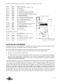
Threads covered by the Insert System (Threads up to 28mm (1 1/8 inch)
Insert
Insert
Insert
Insert
Insert
Insert
Insert
Insert
Insert
Insert
Insert
Insert
Insert
Insert
Insert
2
3
6
7
8
A
B
C
D
E
F
H
I
J
L
(I2NS)
(I3NS)
(I6NS)
(I7NS)
(I8NS)
(IANS)
(IBNS)
(ICNS)
(IDNS)
(IENS)
(IFNS)
(IHNS)
(HNS)
(IJNS)
(ILNS)
:
:
:
:
:
:
:
:
:
:
:
:
:
:
:
Insert
Insert
Insert
Insert
Insert
Insert
Insert
Insert
K
M
N
O
T
U
V
W
(IKNS)
(IMNS)
(INNS)
(IONS)
(ITNS)
(IUNS)
(IVNS)
(IWNS)
:
:
:
:
:
:
:
:
M20 x 2 Tyme Cub
M20 x 1.5 Electra Beckum Multico Sumaro
3/4” Plain Bore
1 1/8” 8 TPI UN RH
7/8” 12TPI NS LH
3/4” 14TPI BSP RH Teknatool (Pre 1986)
3/4” 14TPI BSP LH Teknatool (Pre 1986)
1” 10TPI BSF RH Teknatool Woodfast Durden
1” 8TPI BSW RH General Rockwell Delta Golding
1” 12TPI RH Myford MLS
5/8” Plain Bore Shopsmith
3/4” 10TPI BSW RH Rockwell Homecraft
M24 x 3 RH B Line, Arundel K600 K450
1 1/8” 12TPI RH Myford Mystro
ILNS 1” UNS 8 TPI RH (for DVR lathes
with this thread only)
M18 x 2.5 ELU DB180
1” 1OTPI BSF LH Teknatool Woodfast Durden
Blank. Can be thread up to 28mm 1/8”
1 1/8” BSW RH Morton
1” 8TPI UNC Dual Threaded LH and RH
1 1/8” UNF RH Taiwanese
7/8” 14TPI NF RH
M25 x 2 RH Tyme Avon
Body Internal Spindle
Lathe Spindle
Thread Direct to Chuck
D Chuck
(NSCD)
4 Chuck
5 Chuck
P Chuck
(NSB4)
(NSC5)
(NSBP)
: 1” 8TPI BSW RH
Note: Maximum spindle length 25.4mm
: M33 x 3.5
: 3/4” 16TPI UNF 1/8” spigot
: 1 1/2” BSW RH RTanner Union Graduate
R Chuck
X Chuck
(NSBR)
(NXBS)
: Blank chuck for threads up to 30mm
: 1 1/2” 8TPI NF Conover
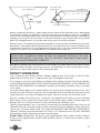
Check insert is
fully home
- NO gap
On lathe must mate against accurate
datum surface/shoulder NO Gap
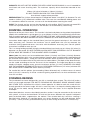
ACTION ADJUSTMENT
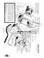
The Nova Chuck has a unique built in action adjustment facility. (NZ Patent Pending Application No.
244229). Please refer to exploded view of the chuck, on Page 5.
By means at the action adjustment the effort required to turn the scroll ring is adjustable.
1 . This will allow you to adjust the feel of the chuck more to your own requirements.
2. Adjust for wear over the life of the chuck.
3. An added feature of the action adjustment is that the movement can be effectively impeded for
special turning requirements. IMPORTANT: THE ACTION ADJUSTMENT SHOULD NOT BE
RELIED ON AS A MOVEMENT LOCK. Normal work mounting procedures and recommendations
in this manual should be followed.
The action adjustment is by means of grubscrew positioned in one o f the three lever hole positions
on the scroll ring. The grubscrew pushes down on a fibre washer which bears against the inner
chuck body. One of the M6 grubscrews (remember to act as a buffer) provided in the fastening kit
needs to be screwed into the threaded hole at the bottom of one of the lever hole positions on the
scroll ring. Note only one of the lower hole positions is threaded at the bottom. Screwing the
grubscrew in (turning it clock-wise) will force the fibre washer against the inner body section. The
more the grubscrew is screwed in, the tighter the chuck action will become. Conversely unscrewing
the grubscrew will give a freer action. By use of this action adjustment feature, over time the action
of the chuck can be adjusted. Only occasional adjustment of the grubscrew should be necessary.
7