1
USER MANUAL
Nordic ID
RF601
Contents
Copyright
1
Disclaimer
1
Trademarks
1
User safety
1
Medical equipment compatibility
2
EC Declaration on Conformity
2
Document history
2
Warranty and safety warnings
3
1.
Using the RF601 for the first time
5
1.1
Unpacking the unit
5
1.2
Installing batteries
5
1.3
The keyboard
6
1.4
Activating the device
6
1.5
Splash screen and initial display
6
2.
System
7
2.1
System overview
7
2.2
Principles of Operation
7
2.3
Communication between the Base Station and the Host Computer
7
2.4
Operation of the Hand terminal
8
2.5
Security
8
3.
Setting up an example system
9
3.1
Fast Inventory -demo
9
4.
RF601 Hand Terminal
11
���������������
4.1
Activating the device
11
4.2
Display symbols and status messages
11
4.3
Sounds
11
4.4
Key function table
12
4.5
F-Keys
13
5.
Input fields
13
5.1
Locked fields (Buttons)
13
5.2
Filling fields with the scanner
13
5.3
Writing text in a field
14
5.4
Writing letters
14
5.5
Removing letters
14
5.6
Moving between fields
14
5.7
Locking the keyboard
14
6.
Built-in Menu
14
6.1
Settings
15
6.1.1
RF-settings
15
“WHAT” Behaviour
15
6.2
Adjustments
15
6.3
Info
15
6.4
Laser conf.
16
8.
Setting up a RF601 network
17
8.1
Site Survey
17
8.2
Installation of the network
17
9.
Using the scanner
17
© 2006 Nordic ID Oy
RF601 User Manual
4
May 2006
Version 1
���������������
10.
Labels
18
11.
Desk Top Charger (DTC05)
19
11.1
General information
19
11.2
Equipment needed for using the charger
19
11.3
Connectors
19
11.4
Indicators
19
11.5
Charging the batteries
20
11.6
“Charging Failure” message
20
11.7
Audible signals and the LED indicator on the hand terminal
21
11.8
Technical data
21
12.
Troubleshooting
22
13.
Maintenance
22
14.
Removing device from the use
22
15.
Warranty, support and service information
23
15.1
Warranty coverage
23
15.2
Returning the unit for service
23
15.3
Extending the normal warranty
23
16.
Application development
24
16.1
Software tools and documents
24
16.2
PLServer, PiccoLink driver ActiveX control
24
17.
Accessories
25
18.
Technical Support
26
19.
Latest information
26
© 2006 Nordic ID Oy
RF601 User Manual
5
May 2006
Version 1
���������������
APPENDIX A - Troubleshooting
27
APPENDIX B - Introduction to the Laser Engine
28
APPENDIX C - Introduction to the Linear Imager
30
APPENDIX D - Factory default settings of the scan engines
31
© 2006 Nordic ID Oy
RF601 User Manual
6
May 2006
Version 1
���������������
Copyright
All rights to this manual are owned solely by Nordic ID. All rights reserved. Copying this manual without the written
permission from the manufacturer by printing, copying, recording or by any other means or the full or partial translation
of the manual to any other language including all programming languages using any electrical, mechanical, magnetic,
optical, manual or other methods or devices is forbidden.
Nordic ID reserves the right to change the technical specifications or functions of its products or to discontinue
manufacturing of any of its products without any written announcement and urges customers to ensure that the information
at their disposal is valid.
Disclaimer
Nordic ID products have not been designed, intended nor inspected to be used in any life support related applications
nor as a part of any other critical system and are not granted functional warranty if used in any such applications.
RF601 contains a Class II laser device, which may cause injuries unless safety regulations and instructions are observed.
Nordic ID may not be held responsible for any injuries or damage resulting from use in contradiction with the safety
related instructions stated elsewhere within this manual or which are in contradiction to the general safetylines relating
to Class II laser devices.
Nordic ID urges its customers to arrange proper and adequate user training, which includes safety issues to any personnel
using, programming or otherwise handling RF601 hand terminals.
The sale, transfer and use of Nordic ID RF601 is subject to the then-current Nordic ID General Conditions of Sale and the
then-current Nordic ID End User License Agreement, the then-current referring to the original purchase date.
Trademarks
Nordic ID and Nordic ID logo are all registered trademarks of Nordic ID Oy. Other trademarks are the property of their
corresponding owners.
All terms mentioned in this User Manual that are known to be trademarks or service marks have been appropriately
marked in the list below with either the ©, ® or the ™ symbol.
Nordic ID cannot attest to the accuracy of this information. Use of a term in this User Manual should not be regarded as
affecting the validity of any trademark or copyright.
User safety
CAUTION: In some configurations of the RF601 barcode scanner contains an integrated Class II laser product. Direct eye
contact with the laser beam or with a reflected beam from a shiny surface may cause permanent damage to the eyes. To
avoid risks, please make sure that never look directly to the laser and/or point anybody with the device.
© 2006 Nordic ID Oy
RF601 User Manual
1
May 2006
Version 1
���������������
Medical equipment compatibility
Medical devices, such as pacemakers, hearing aids etc. are usually manufactured according to the IEC 601-1-2 standard,
which requires that devices must operate properly in an EM (Electromagnetic) field which has a strength of 3V/m over a
frequency band from 26 to 1000 MHz. The RF601 is transmitting at a frequency range of 433.60 to 434.20 MHz, however,
all electric appliances may emit spurious RF-signals at other than specified frequencies.
WARNING: Persons using pacemakers should be aware of the possible risk of interference from any electronic device if
positioned too close to the pacemaker.
EC Declaration on Conformity
Nordic ID hereby declares, that Nordic ID RF601 wireless data collection system has been tested according to the
standards EN 300 200-1 and EN 301 489-3.
The equipment conforms to the essential requirements of the Directive 1999/5/EC.
Document history
March 2006
May 2006
© 2006 Nordic ID Oy
RF601 User Manual
Draft1
Release version
2
May 2006
Version 1
���������������
Warranty and safety warnings
Please read the following warranty and safety related warnings carefully before using the product.
Nordic ID RF601 is a radio device and should not be used in any environments where radio transmitting may cause any
harm. Typical but not limited to are the following types of environments: environments with explosive materials, liquids
or gases, demolition sites, hospitals and emergency care rooms, airplanes and areas with highly sensitive measurement
instrumentation.
Users with pacemakers are to be instructed about the possible safety hazards posed by radio emitting devices. Placing
any radio emitting device near to pacemakers is not recommended. Consult pacemaker documentation for further safety
regulations and requirements set by manufacturer of the pacemaker in question.
NOTICE: Persons using pacemakers should be aware that RF-emissions from the RF601 may cause unwanted
interference if positioned too close to the pacemaker.
NOTICE: RF601 has not been designed, intended nor inspected to be used in any life support related device or
system related function nor as a part of any other critical system and are granted no functional warranty if they
are used in any such applications.
The use of any radio emitting device in explosive environments and especially near explosives may pose serious
threats.
RF601 models contain a laser barcode reader device. Users are advised to follow general safety procedures relating to
the use of laser devices.
Nordic ID RF601 should not be used in critical systems where continuous operation is required and where the possible
loss of data or unwanted changes to data contents are not acceptable, such as in life support related systems.
Warranty will be void, if the product is used in any way which is in contradiction with the instructions given in this User
Manual, or if the housing of the RF601 has been opened or tampered with.
The devices mentioned in this manual are to be used only according to the instructions described in this manual. Faultless
and safe operation of the devices can be guaranteed only if the transport, storage, operation and handling of the devices
are appropriate. This also applies to the maintenance of the products.
RF601 contains no user serviceable parts inside the actual case apart from the batteries, which may be replaced if
required.
NOTICE: Use only AA-type alkaline batteries or rechargeable batteries type: GB Batteries, Models GP180AAHC,
GP210AAHC and GP230AAHC (GPI International). Do not mix batteries (do not use simultaneously batteries
of different capacity, brand, age or type). Observe correct polarity indicated on the label inside the battery
compartment. Do not attempt to charge alkaline or other non-rechargeable battery types using the Hand Terminal
and the Desk Top Charger or any other charger. When charging batteries inside the terminal use ONLY charger
provided by Nordic ID.
NOTICE: With use of Desk Top Charger and Base Station use only applicable power supplies: JODEN ELECTRON
Co., Ltd, Models: JOD-4101-031, JOD-41B-029, JOD-41U-14A.
WARNING: The batteries must be discarded according to local environmental laws and regulations. The batteries
may contain harmful, dangerous or lethal substances, and may cause injury or loss of life if handled recklessly.
Never dispose the batteries in fire due to a risk of explosion.
Any repair of the RF601 must be done by an authorized service partner of Nordic ID.
© 2006 Nordic ID Oy
RF601 User Manual
3
May 2006
Version 1
���������������
WARNING: The RF601 Hand Terminal and Desk Top Charger and power supply contain no user serviceable parts.
Opening the cases will void warranty and may cause injury. The Hand Terminal contains batteries, which may be
changed by opening the battery cover.
In some configurations the RF601 contains a Class II laser device which may cause eye injury if the beam is directed
straight or via a shining surface to the eye. The laser beam should never be pointed at the eye or eyes of persons or
animals. Note that mirrors and reflecting surfaces may cause the beam to deflect in harmful ways. Never look directly into
the laser module when the beam is active.
In Accordance with
EN 60825-1 / A2:2001
(IEC 60825-1 Ed.1.2,2001-08)
650 nm laser
max. 1 mW output
ENGLISH
LASER LIGHT
DO NOT STARE INTO BEAM
CLASS 2 LASER
SUOMI
VAARA LASERSATEILYÄ
ÄLÄ TUIJOTA SÄTEESEEN
LUOKKA 2 LASER
DEUTSCH
LASERSTRAHLEN
NICHT DIREKT IN DEN LASERSTRAHL SCHAUEN
KLASS 2 LASER
SVENSKA
VARNING LASERSTÅLNING
STIRRA EJ IN I STRÅLEN LASERPRODUKT DER KLASSE 2
DANSK
LASERLYF
SE IKKE IND I STRÅLEN
KLASSE 2 LASER
ITALIANO
LUCE LASER
NON FISSARE IL RAGGIO PRODOTTO
AL LASER DI CLASSE 2
FRANÇAIS
LUMIERE LASER
NE PAS REGARDER LE RAYON FIXEMENT
PRODUIT LASER DE CLASSE 2
ESPAÑOL
LUZ LASER
NO MIRE FIJAMENTE EL HAZ
PRODUCTO LASER DE LA CLASE 2
NEDERLANDS
LASERLICHT
NIET IN STRAAL STAREN LASERLYS
KLASSE-2 LASER
NORSK
IKKE STIRR INN I LYSSTRÅL
LASER, KLASSE 2
PORTUGUÊS
LUZ DE LASER NÃO FIXAR O RAIO LUMINOSO
PRODUTO LASER DA CLASSE 2
© 2006 Nordic ID Oy
RF601 User Manual
4
May 2006
Version 1
���������������
1. Using the RF601 for the first time
1.1
Unpacking the unit
The RF601 Hand Held Unit packing includes:
•
•
•
RF601 Hand Held Unit
Nordic ID User Manual CD and/or book
Rechargeable batteries (optional)
The Demo-packing includes also:
•
•
•
•
Base Station
2m Cable between Base Station and Serial port )
Desk Top charger DTC05
Configuration cable (831)
Remove the unit from the packing and check that all above is included. Save the packing for possible future purposes.
1.2
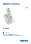
Installing batteries
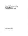
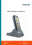
Before using the RF601 install 2 AA-sized alkaline or fully charged rechargeable batteries as shown in the figure 1.
+
-
+
+ -
- +
Fig. Installing batteries to the RF601
© 2006 Nordic ID Oy
RF601 User Manual
5
May 2006
Version 1
���������������
1.3
The keyboard
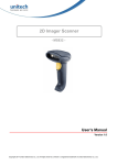
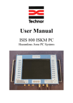
RF601 has 22 button keyboard; scan-key, 5 programmable function keys F1-F5, OK, shift and Up-Down movement –key,
12 alpha/numeric keys and a DEL-key.
Scan -key
Shift -key
OK -key
Programmable function keys
Programmable function keys
Up / Down movement -key /
charging led
Alpha / numeric -keys
Del -key
Fig. Keyboard of the RF601
1.4
Activating the device
The Hand Terminal has no On/Off switch. The Hand Terminal is always (when batteries are powered) ready to function by
pressing any key. When resetting (SHIFT+DEL) or installing batteries the Hand Terminal beeps twice. The Hand Terminal
will resume its standby state 30 seconds (default, configurable to max 254 seconds) after the last function.
1.5
Splash screen and initial display
A splash screen is a displayed immediately after the batteries are installed. This screen is fully configurable to display any
characters on the keymaps.
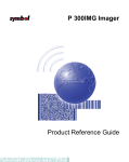
An initial display will always appear if no fields are defined. This will usually occur when the Hand Terminal is activated
or its RAM is cleared. The initial display includes a heading which can be defined by the user and an input field of max.
18 characters.
Fig. Intial display of the device
© 2006 Nordic ID Oy
RF601 User Manual
6
May 2006
Version 1
���������������
2.
System
2.1
System overview
The Nordic ID RF601 Wireless Data Collection System consists of three principal components:
•
Nordic ID RF601 Hand Terminal(s)
•
Nordic ID RF601 Base Station(s)
•
The application software that runs on the Host Computer
This picture (figure 4) illustrates how a Nordic ID RF601 operates. The information will be sent from the handheld terminal
via the base station to the host application. In some configurations the base station includes an ethernet connector which
can be used to connect the base station to the host computer via LAN network.
2.2
Principles of Operation
The Nordic ID RF601 is a Hand Terminal which communicates wireless with PC application software via Nordic ID RF600
Base Station(s). A Base Station can be connected directly to the Host Computer using an RS232C interface, or via
network by using the Ethernet connector (optional feature). The Hand Terminals can send/receive data to/from the Host
Computer using the specific Communication protocol. Data transfer between the system components is always check
summed and acknowledged. This prevents any loss of data.
2.3
Communication between the Base Station and the Host Computer
The Base Station keeps listening the radio channel and the RS232C interface this is in order to check if the Hand Terminals
or the Host Computer have data to send. When the base Station receives data from the Hand Terminal, it verifies the
integrity of the data frame by using CRC check summing; only correct messages are then passed to the RS232C port.
The CRC is not removed from the message so that it can be used to check the hardware link between the Base Station
and the Host Computer.
When the Base Station receives a data from the Host Computer, the CRC checksum is recalculated for the data frame.
Only if the message is correct will it be transmitted to the radio channel.
Fig. Diagram of the communication
© 2006 Nordic ID Oy
RF601 User Manual
7
May 2006
Version 1
���������������
2.4
Operation of the Hand terminal
The RF601 Hand Terminal is designed to use application specific forms, so called fields in the virtual display. This helps
to make the user interface of the Hand Terminal flexible and easy-to-use. The commands in use to generate, modify, read
and write the forms are described in the document called “RF-series system developers quide”.
When no forms are used, the initial screen of the Hand Terminal prompts an initial display and an input field. This field
can be filled with data from the keyboard or from a scanner. Any text sent by the Host Computer will clear the screen and
show the text that was sent. Any user input (from the keyboard or laser scanner) will clear the text and the initial screen
will be displayed again.
The user starts a transaction by making the entry using the Hand Terminal keyboard or reading a barcode. Then the Hand
Terminal sends this data to the Host Computer (via the Base Station) and waits for a message from the HOST. If it does
not receive a correct (check summed) message within the specified time limit, it will resend the original data as many
times as it has been programmed to do.
Note: When no entry is made on the Hand Terminal by the user, the hand terminal remains in a standby state and will
not be able to receive data from the Host Computer. There are some exceptions to this which will be described in the
RF-series system developers guide.
2.5
Security
RF technology offers a good level of data transfer security. It is necessary that no external part without a proper
authentication is able to access the network with capable device.
Security implementation on the Nordic ID RF601 system is based on three factors
• User authentication
User has to identify him/herself. This may include a password and user name input screen defined by the Host Application
and displayed as the first screen visible to the user trying to connect to the Host Application
• Device authentication
To increase security of the Nordic ID RF600 system, the host application will handle only those hand terminals which
serial number match with the specific list of hand terminals provided by the host application.
The CommID of the Hand Terminal can be used to distinguish between an allowed and rejected Hand Terminal used in
the RF601 network.
• Radio link encryption
By default, the radio link between the RF601 hand terminal and the base station is not secured. Messages sent by the
hand terminal can be read with the base station, which is operating in same channel. Data from the hand terminal input
fields can be read with any terminal program (ex. hyper terminal).
A Message from the HOST to the hand terminal is secured because the base station cannot read another base station
messages.
In cases where encryption is specially needed, can user authorization be used for accessing to the computer system.
Password and user ID information must be secured by encryption.
© 2006 Nordic ID Oy
RF601 User Manual
8
May 2006
Version 1
���������������
3.
Setting up an example system
The example system can be created quite easily with demos available from our website. Download and install
RF6xxDemoPack.exe which is the installation packet of four host demo application for the RF6xx hand held devices.
3.1
Fast Inventory -demo
This is detailed description how to use hand terminal set with the Fast Inventory demo application. The Fast Inventory is
a simple application for collecting data to the specific text file using the RF-series hand terminal.
Equipment needed:
• RF601 hand terminal
• RF601 Base station + Power supply + serial cable
• PC with Windows operating system and serial port (COM)
1. Download and install RF6xxDemoPack.exe to your computer.
2. Connect the serial cable between the PC COM port and the Base station. You need to know COM port number.
3. Plug power supply to the base station. (Green Rx led will be lit)
4. Open Fast Inventory -program from the PC start menu: <START>->Programs->RF6xxDemoPack->Fast Inventory
5. Select correct COM port number from Fast Inventory program “Serial Connection” and press “StartServer” button
to start the application.
6. If successful COM connection, COMx (where the x is the number of COM port) text appears in below the “Nordic ID
RF6xx Driver Control “ text.
7. If text is “CreateFileError”, the COM port might be already used by another program.
8. Put fresh batteries to the hand terminal and press OK or any F-key for transmitting.
9. Fast Inventory application answers by displaying user interface screen on hand terminal.
10.Start using Fast Inventory Application by scanning a barcode. The program will save it to Inventory file, located at
path displayed at Inventory file box.
If terminal does not communicate with the host program:
• Make sure that the hand terminal and the base station are in the same channel. (Factory default is 3)
• Make sure that COM port number is correct. (may vary depending on computer)
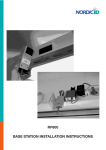
When the hand terminal connects first time to the Fast Inventory program, following screen appears to the hand terminal
screen:
© 2006 Nordic ID Oy
RF601 User Manual
9
May 2006
Version 1
���������������
Fig. Fast Inventory -demo
The hand terminal user can type a count and scan a code of product: After scanning the code with the hand terminal,
data will be transmitted to the host and saved to the specific Inventory file.
Fields are separated by semicolon (;): (code ; count ; date ; hand terminal ID )
f. ex: 023942874102;15;20.9.2004 9:07:55; 1959
The RF6xx Demo applications have several methods for connecting the base stations to the sample application.
• COM port: The most simple way is to connect RF601 base station directly to the demo application by using a PC
COM port. Serial connection can be opened from the demo application by using the “Serial Connection” combo
box:
• TCP/IP server: The base stations can be physically installed to the other computer or network server. The demo
application can “listen” remote base station connections by activating “Start Server” and listening specific port for
incoming connections.
• Serial Server Connection: If the base stations are connected to the LAN by using serial to TCP/IP converters, then
the user can use “Serial Server Connection” for creating connection to the base station. User has to know the TCP/IP
address and the port number of the serial server.
© 2006 Nordic ID Oy
RF601 User Manual
10
May 2006
Version 1
���������������
4.
RF601 Hand Terminal
4.1
Activating the device
The Hand Terminal has no On/Off switch. After installing batteries Hand Terminal is always ready to function by pressing
any key. When resetting (SHIFT+DEL) or installing batteries the Hand Terminal will beep twice. The Hand Terminal will
resume its standby state 30 seconds after the last function and it remembers its last state.
4.2
Display symbols and status messages
Special symbols will be shown on the right side of the display depending on the function:
SHIFTLOCK. This function will be ON or OFF by pressing the shift key,.
TRANSACTION. This sign shows up, when the Hand Terminal is communicating with the HOST.
TRANSACTION FAILURE. This sign shows up, when transaction between the Hand Terminal and the HOST
has failed. This will also be indicated by four beeps.
LASER. This sign shows up, when the laser reader is activated. (yellow laser button)
The status messages are displayed at the bottom of the display. These messages contain information about and the
device and its state. These messages are recognised by the black backround of the text.
4.3
Sounds
Resetting Hand terminal
Transaction failure
Bad battery condition
Reception of message
Successful reading of laser scanner
Opening keylock
Wrong password
© 2006 Nordic ID Oy
RF601 User Manual
2 beeps.
4 beeps
3 beeps with different levels
At least 1 beep, can be more.
1 beep
1 long beep
3 fast beeps
11
May 2006
Version 1
���������������
4.4
Key function table
Key
Function with shift key
(shift + key pressed at
the same time ).
Laser
***
F1
RECEIVER mode ON/
OFF
***
***
***
***
F2
F3
F4
F5
OK
Arrow
up
Arrow
down
Shift
7
8
9
4
5
6
1
2
3
.
0
-
Function with
SHIFTLOCK
Normal function
External reader or RFID
The Laser reader will be activated if
reader activation, if
allowed by the current input field.
available.
F6
F1
F2
F3
F4
F5
The cursor will be moved to the next
field and/or the content of the field
Keylock ON / OFF
Normal function
sent to the HOST if allowed by the
current field
Moves the cursor step Displays the previous field of the
Scrolls display upward
by step to the left.
form.
Scrolls display
Moves the cursor step
Displays the next field of the form.
downward
by step to the right.
***
SHIFTLOCK OFF
SHIFTLOCK ON
***
ABC abc
7
***
DEF def
8
***
GHI ghi
9
***
JKL jkl
4
***
MNO mno
5
***
PQR pqr
6
***
STU stu
1
***
VWX vwx
2
***
YZÅÄÖ yzåäö
3
***
.
↵:;!?”#&@|
MENU
0
<>[]Ü{}()ü
Spc + * / % = $ £ ±
Backlight (option)
-
DEL
F7
F8
F9
F10
½
Reset
Normal function
Removes a character from the current
field.
Table: Key function table
NOTE: The characters depends on the keymap used.
© 2006 Nordic ID Oy
RF601 User Manual
12
May 2006
Version 1
���������������
4.5
F-Keys
The F-Keys <F1> - <F10> can be programmed with a special configuration program to include recurring strings.
The F-Keys function in two different ways:
• By pressing an F-key, the string of characters is sent to the Host Application. This is the default setting.
Example: When the user presses F1-key, the string “F1” will be sent to the Host Application.
• By pressing an F-Key, a string is printed in the current field. If the length of the string exceeds the length of the field,
the excess characters will be omitted. If the field already contains text, it will be replaced by the new text.
A string of characters in the initial display can be sent to the HOST by pressing the OK button or read with a laser
scanner.
5.
Input fields
The Nordic ID RF601 Hand Terminal has a virtual display page of 12 x 20 characters. The actual display size is 8
x 20 characters, thus 2/3 of the virtual page can be viewed at a time. Rows may be scrolled by pressing the keys
accordingly.
Depending on the Host Application, the Host Application can send fields to the Hand Terminal. These fields may be filled
by using the keyboard or the laser scanner. Fields are underlined.
5.1
Locked fields (Buttons)
Fields can generally be filled with text using the keyboard. Locked fields are an exception to this rule. When a locked
field is active, the text in the field is highlighted (black background with white text). The laser scanner cannot be used to
fill a locked field. A locked field functions like a button and the contents of the field can be sent to the Host Application
by pressing the <OK> key.
5.2
Filling fields with the scanner
It is possible to define input fields to have different behaviour when filling an input field with the laser scanner: Typically,
the scanning result goes to the active input field (where the cursor is). Alternatively, if the form has an input field which is
defined as a “DEFAULT_LASER” field, the scanning result is copied into that field regardless of whether it is active or not.
If the field already contains text, it will be replaced by the new text.
1. A field can be filled using the laser scanner and be sent to the HOST immediately Example: typical stock taking
situation.
2. A field can be filled using the laser scanner but not sent to the HOST.Example: the user needs to verify the text
string contents before sending to the Host Application.
3. A field cannot be filled with a laser scanner. Example: the field requires the user to input other information, for
example numbers.
© 2006 Nordic ID Oy
RF601 User Manual
13
May 2006
Version 1
���������������
5.3
Writing text in a field
An active field is indicated by the cursor. An active field can be filled with text by using the keyboard and/or by using the
laser scanner.
You can move the cursor in the field step-by-step by using the keys if SHIFTLOCK-function is ON (the symbol will be
visible in the right lower part of the display).
5.4
Writing letters
Letters can be written into a field when the SHIFTLOCK is ON (the symbol will be visible in the lower right part of the
display) by pressing the proper number keys (the letters are also printed into the keys). When a key is pressed once the
first printed letter on the key will be generated. When pressed quickly twice the second letter printed on the key will be
generated etc.
Pressing a key for at least 1.2 seconds will change the letter from uppercase to lowercase and vice versa.
5.5
Removing letters
Letters can be removed from a field with the <DEL> key.
Pressing the <DEL> key for at least 0.5 seconds clears the entire field of any text.
5.6
Moving between fields
You can move between the fields by using the <> keys. By pressing the <OK> key, you can move to the next field.
5.7
Locking the keyboard
The keyboard may be locked by pressing the <SHIFT> key and while keeping it pressed by pressing the OK-key (second
function of the <OK> button).
6.
Built-in Menu
The settings of the Hand Terminal can be changed through the Menu. The Menu can be activated only if the initial display
is on by pressing the keys SHIFT + 0.
You can move in the Menu by using the <> keys. The desired item is selected by pressing the <OK> key. You can move
backwards in the Menu by selecting the << choice and pressing <OK>.
For changing existing settings values, delete previous value using the <DEL> button. Type in the new value and press
<OK>.
After choosing an item in the Menu, confirm the selection by pressing the <OK> key. Changed setting will be signalled
by a beep.
© 2006 Nordic ID Oy
RF601 User Manual
14
May 2006
Version 1
���������������
6.1
Settings
Settings-menu contains functionalities for managing RF-connections. After selecting Settings from the Main Menu, a 4digit password is required. Usually only a representative of the system integrator has access to these settings. By default
the password is 0000, entering that and pressing <OK> will open Settings menu.
6.1.1 RF-settings
Channel
In this menu user can choose communication channel from 1 to 7. Note that the channel must be same in the
HOST-computer.
Resending times
How many times a message is sent to the HOST if no answer is received. If the Hand Terminal cannot get a
response from the Base Station, and all the resending times have been used, the transaction failure sign F will
be prompt on the display.
Reception timelimit
The time limit during which the Base Station must respond to the Hand Terminal before the message is resent.
Timelimit can be chosen between 1 – 15 seconds.
“WHAT” Behaviour
In this menu user can choose “WHAT” command behaviour between 2 types: the New and the Old one. The
difference between these is explained in RF6XX System Integrator Guide. The default is 0 (new style).
6.2
Adjustments
This menu contain general settings of the Hand Terminal
Contrast
Key sounds
Volume
Battery type
6.3
Display contrast (0 - 100%)
0=Off / 1=On
Beeper level and frequency.
0, if NI-CD or NI-MH rechargeable batteries are used. 1, if using normal
batteries.
Info
This screen shows some basic info about the RF601.
Header
commID
Charmap
Battery
© 2006 Nordic ID Oy
RF601 User Manual
Device and Firmware version
The communication identification number of the device
Active charactermap in use
Battery charge level indicator
15
May 2006
Version 1
���������������
6.4
Laser conf.
The user can fill this input field by activating the scanner and by using the scanner to read a barcode.
This feature may be used to test the reader functionality and programming the laser module. A special use of this feature
relates to the programming of the laser module with the help of special programming barcodes provided Nordic ID. For
further information about programming the laser module, please contact Nordic ID Technical Support (support@nordicid.
com).
The scanner can also be configured “on-line” from the backend software. This feature is explained in the document “RFseries system developer guide”.
7.
RF601 Base Station
RF601 Base Station creates the radio network required for the data transmission between Hand Terminal(s) and Host
system. Base station supports 7 channels which each can support several users simultaneously. The base station can
be connected to the host system using an RS232 serial interface or to LAN (Local Area Network) using the Ethernet
connector (optional).
The Base Station has an RS232C port with fixed settings 19200 bauds, no parity, 8 data bits, and 1 stop bit. It uses RTS/
CTS hardware handshaking in the direction HOST-> Base station.
The configuration of the (optional) ethernet connector is done by specific software avalable from Nordic ID.
Fig. The Nordic ID RF601 Base Station
© 2006 Nordic ID Oy
RF601 User Manual
16
May 2006
Version 1
���������������
8.
Setting up a RF601 network
This chapter describes the basics of building the RF601 network. Detailed info can be found on document “RF6XX
System integrator guide” available from Nordic ID Partner Login Area at www.nordicid.com.
8.1
Site Survey
Site survey is a Radio Network operation survey on an actual user environment. This means that Base Stations are placed
to the desired positions at the site and then measurements are made to check how the connection signals changes. By
doing this the base station(s) can be positioned to best possible places.
Enter the Site survey -mode by typing “TST” in the password field. The site survey shows all the RF601 Base Stations in
the range, their CommID number and the RSSI (Radio Signal Strength Indicator) value. Bigger value means better signal
strength.
8.2
Installation of the network
The network is build by using base stations that cover the area where Hand Terminals is being used. Base Stations must
configure to work as a network with a specific configuration tool available from Nordic ID by request.
In theory the best place to install a Base Station is at middle of the area to be covered. However the frequencies used in
RF601 system can be heavily attenuated by object between the Terminal and the Base Station.
The actual installation of Base Stations must be made by authorized personnel and followed by local legislation.
9.
Using the scanner
User can read barcodes depending on configuration of the handheld unit. See Appendix for more info about scanner
configuration.
1. Hold the RF601 at a slight angle about 10 – 30 cm (few inches) from the barcode label to be read. If the surface of the
barcode label is very reflective, scanning from directly above (90° angle) may cause reading errors.
2. Push the <SCAN> button on the keypad while directing
the beam so that the beam covers all of the bars on
the label. A beep or audio signal will be generated
indicating that the scanner has successfully read the
label. The scanner will stay on or it will automatically turn
off depending on the scanning options, During normal
operation, the beam will be switched off immediately
after the barcode has been read successfully.
© 2006 Nordic ID Oy
RF601 User Manual
17
May 2006
Version 1
���������������
10. Labels
The labels are located backside of Hand Terminal and inside the battery compartment.
The labels inside the battery compartment may be read by removing the battery compartment cover and the batteries. The
label also contains markings to indicate the correct orientation and polarity of the batteries or re-chargeable batteries.
Label includes the following information:
• Type of the Hand Terminal
• Serial number of the Hand Terminal
• CommID (a communications identification number, which can be used by the Host Application to identify a particular
Hand Terminal)
• The configuration code of the hand terminal
Fig: Type label of the RF601 hand terminal
Please note that there might be several types of Hand Terminals with different configuration. For further details please
contact Nordic ID or your local reseller.
The CommID (Communication ID) is a fixed number, which is used to identify transmissions. In RF600 system this number
was the same as the serial number of the device. CommID range is between 0 and 65535.
The laser light caution label is located backside of the hand terminal.
© 2006 Nordic ID Oy
RF601 User Manual
18
May 2006
Version 1
���������������
11.
Desk Top Charger (DTC05)
The RF601 Hand Terminal may be powered either by using alkaline batteries (AA-type 1.5V batteries) or by using NiMHtype AA-size rechargeable batteries. Note that the only approved type of rechargeable batteries is: GB Batteries (GPI
International) Model: GP180AAHC.
When using NiMH-type batteries an optional Desk Top Charger is available. The information in this chapter applies to the
single Hand Terminal Desk Top Charger (DTC05) but applies also basically to the Multiple Desk Top Charger unit, with
which it is possible to charge up to five Hand Terminals simultaneously.
11.1
General information
The Desk Top Charger is used for charging the rechargeable batteries of the Nordic ID RF601 Hand Terminal. It is a fast
charger which reduces the charging time. Using the Desk Top Charger the batteries may be charged without removing
them from the Hand Terminal. The charging procedure is directed through the Hand Terminal.
11.2
Equipment needed for using the charger
• Desk Top Charger
• Power Supply (see approved models at the chapter “Warranty and safety information” at page 3 of this manual)
• Approved type of AA-size rechargeable batteries
• Nordic ID RF601 Hand Terminal
11.3
Connectors
The only connector of the charger is for the power supply.
Fig. The power connector of the charger
11.4
Indicators
The charging indicator, which shows the charging status of the batteries is located in the up/down -key of the hand
terminal. The hand terminal indicates the charging For more information see section: 11.7 Audible signals and the LED
indicator on the hand terminal
© 2006 Nordic ID Oy
RF601 User Manual
19
May 2006
Version 1
���������������
11.5
Charging the batteries
WARNING!
Do not attempt to charge regular or alkaline batteries as
this may cause an explosion.
Do not place a defective Hand Terminal into the charger.
Use only approved type of rechargeable batteries.
NOTICE! Use only approved type of power supplies (see
chapter “Warranty and safety warnings” at page 3 of this
manual).
The Hand Terminal cannot be used during battery charging.
It is normal for the base of the charger to become warm
during charging.
Fig. The Nordic ID RF601 and the charger
Requirements for using the Desk Top Charger:
• Batteries must be placed inside the Hand Terminal to allow charging.
• Check that the Hand Terminal batteries are of rechargeable type (NiMH).
• Check that the settings for the Hand Terminal have been configured as follows:
MENU > ADJUSTMENTS > BATTERY > 0. (See User Manual: MENU).
• Connect the power supply adapter (9525) to the power supply connector of the charger (see picture).
• Place the Hand Terminal in the charger.
• The Hand Terminal will beep and start to charger the batteries in full charge mode.
• If the rechargeable batteries are already fully loaded, the charger goes into trickle mode automatically.
• The charging indicator LED will remain ON during quick charging.
• The LED will start to blink when the battery is fully charged. The charger will switch over to trickle charge mode.
11.6
“Charging Failure” message
When placing the Hand Terminal into the charger, the Hand Terminal will check the functionality of the charger. If the
Hand Terminal notices that the charging procedure cannot be started normally, a “Charging Failure” message appears
to the display along with three successive beeps. In this case, remove the Hand Terminal from the charger immediately
and check the batteries (should be of rechargeable type and approved manufacturer and capacity rating and installed
observing the correct polarity marked on the Hand Terminal label inside the battery compartment) and then try again. If
“Charging failure” message appears every time when placing the Hand Terminal into the charger, it is possible that the
Desk Top Charger does not work properly.
It is also possible that the Hand Terminal causes the “Charging Failure” message.
© 2006 Nordic ID Oy
RF601 User Manual
20
May 2006
Version 1
���������������
11.7
Audible signals and the LED indicator on the hand terminal
The status of the Desk Top Charger charging process is indicated by the LED indicator located on the front side of the
Hand Terminal base and by audio signals generated by the Hand Terminal.
CHARGING INDICATOR LED
Quick charge – the red LED remains on and batteries are charged with full charging current
Trickle charge - the red LED blinks and trickle charger mode will maintain the charge level of the batteries at
full level.
AUDIBLE SIGNALS
Three successive beeps - charging not allowed (the Hand Terminal does not contain rechargeable type
batteries.
Two successive beeps (long beep followed by short beep) - The battery is being charged.
NOTICE! TO AVOID DAMAGE OR ACCIDENTS, THE DESK TOP CHARGER MUST NOT BE USED FOR ANY OTHER
PURPOSE THAN THAT STATED IN THIS MANUAL.
USE FOR OTHER PURPOSES NOT STATED IN THIS USER MANUAL MAY VOID WARRANTY.
11.8
Technical data
Rechargeable batteries
Charging methods
Charging current
Charging time
Size AA, (see chapter “Warranty and safety warnings” at page 3 of this manual)
Quick charge and trickle
800 mA
Ca 1,5 h (1800 mAh battery)
© 2006 Nordic ID Oy
RF601 User Manual
May 2006
21
Version 1
���������������
12.
Troubleshooting
In case of problems encountered during the use of the RF601, please contact your system integrator or your local Nordic
ID dealer.
The following Guidelines are to be followed when optimal working distance needs to be determined or if barcode decoding
related problem is encountered.
NOTE: Due to the large variety of symbol sizes, densities, print quality, etc., there is no simple formula to calculate
the optimum symbol distance.
1.
Measure the maximum and minimum distance at which your symbols can be read.
2.
Locate the scan engine so that the symbol is near the middle of this range when being scanned.
3.
Check the near and far range on several symbols. If they are not reasonably consistent there may be a printing
quality problem that can degrade the performance of your system.
4.
Center the symbol (left to right) in the scan line whenever possible.
5.
Position the symbol so that the scan line is as near as possible to perpendicular to the bars and spaces in the
symbol.
6.
Avoid specular reflection (glare) off the symbol by tilting the top or bottom of the symbol away from the engine.
The exact angle is not critical but should be large enough to allow the reflected scan line to miss the window of
the laser engine.
7.
Check that the window is clean.
8.
Give the scan engine time to dwell on the symbol for several scans. Poor quality symbols may not read on
the first scan. When first enabled, the scan engine may take two or three scans before it reaches maximum
performance. Enable the scan engine before the symbol is presented, if possible.
13.
Maintenance
The RF601 display window and the laser scanner window may be cleaned with a clean, non-abrasive, lint-free cloth. Under
no circumstance use alcohol or detergents, as these may harm the materials of the casing and/or remove markings.
14.
Removing device from the use
When removing the device from use in EU area, the device must be returned to local Nordic ID
office or to Nordic ID service center. Please see www.nordicid.com or your supplier to find nearest
Nordic ID office or Service center. Returning the device to Nordic ID enables reuse of the materials
in the device. If the device is left to nature hazardous substances in the equipment may have
effects on environment and human health.
Wasted Nordic ID RF601 handheld and accessories must be collected separately.
© 2006 Nordic ID Oy
RF601 User Manual
22
May 2006
Version 1
���������������
15.
Warranty, support and service information
If you encounter problems during the use of the Nordic ID RF601, please contact your system integrator or local Nordic
ID dealer.
15.1
Warranty coverage
Nordic ID grants warranty to its products according to Nordic ID General Sales Conditions.
Only service companies authorized by Nordic ID have the qualified service maintenance facilities and know-how for the
servicing of RF601.
NOTE: Service attempts by unauthorized personnel will void warranty.
15.2
Returning the unit for service
The Product shall be returned to the Manufacturer for repair in case the System Integrator or the local Nordic ID dealer
cannot help with the problem. Each party will bear the cost of freight of the Product to be repaired to the intended
destination.
Please include a detailed description of the problem encountered and a copy of the original purchase order / receipt
together with full return address and contact information (name of the sender, contact phone number, email address) with
the shipment and send it to authorized service location.
15.3
Extending the normal warranty
Repair service done by the Manufacturer after the warranty period will be charged according to the valid service price list.
The repair service is valid for five years after shipping the Product to the System Integrator or the local Nordic ID dealer.
Upon request the Manufacturer may extend the normal warranty period. This must be requested using a separate
quotation request addressed and sent to the System Integrator or local Nordic ID dealer.
© 2006 Nordic ID Oy
RF601 User Manual
23
May 2006
Version 1
���������������
16.
Application development
The Nordic ID RF601 data collection system interface for 32-bit Windows environment is easy by using the ActiveX
technology. PLServer is ActiveX software component for communication between the hand terminal and the Host
application.
Tools for the RF601 software development is available by request. To register and order the tools package please contact
Nordic ID by email using the address [email protected] or via your sales contact.
16.1
Software tools and documents
Software tools and documents available from Nordic ID contains demo applications and some configuration software
applications required e.g. if updating the firmware of the RF601.
Tools and documents include:
• RF601 User Manual (this document)
• CD-ROM contains the following software
- Various demo software
- Configuration software
- Programming examples (code examples)
- Nordic ID Port Router
• Desk Top Charger with power supply and mains cable (EU, UK or US version)
• Configuration cable
• Boot cable
16.2
PLServer, PiccoLink driver ActiveX control
The Nordic ID RF601 driver control is a 32-bit Windows ActiveX control ( PLServer.ocx ), which controls the data
communication between the base station and the HOST application.
PLServer makes HOST system software development easy because it does all the dirty work for you. The use of PLServer
provides a lot of functionality and code that you don’t have to write or debug. All you have to do is to figure out the entry
points and how to use them.
You can use PLServer control in applications that are developed with Visual Basic, Visual C++, .NET, Excel, Access,
FoxPro, Delphi and many more products that support ActiveX controls.
© 2006 Nordic ID Oy
RF601 User Manual
24
May 2006
Version 1
���������������
17.
Accessories
• Holster with Belt Clip (574)
• Full Cover Holster (575)
• Shock Absorbing Cover in 3 colors; grey, turquoise and orange
• Multiple Desk Top Charger
• Cable Kit (900) which includes:
• 2 pcs BS-extension cable with RS-11 connectors 10m (920)
• BS extension socket with DC-cable (925)
• BS extension socket (927)
Cables can be also sold separately. Ask your local Nordic ID dealer or mail to [email protected].
© 2006 Nordic ID Oy
RF601 User Manual
25
May 2006
Version 1
���������������
18. Technical Support
The System Integrator or your local Nordic ID dealer or primarily provides all non-service related technical support.
Nordic ID as a hardware manufacturer provides the hardware repair related technical support.
Please use the e-mail address below when technical support is required:
Nordic ID Head Office
Myllojankatu 2A
FIN-24100 SALO
FINLAND
Telephone
Fax
+358 – 2 – 727 7700
+358 – 2 – 727 7720
Technical Support
Telephone
+358 – 2 – 727 7736 direct
Fax
+358 – 2 – 727 7720
[email protected] (7 – 16 CET)
19.
Latest information
For latest information on RF601 and related products and on possible changes to this manual please consult our Webpages at:
www.nordicid.com
© 2006 Nordic ID Oy
RF601 User Manual
26
May 2006
Version 1
���������������
APPENDIX A - Troubleshooting
In case of problems encountered during the use of the RF651, please contact your system integrator or your local Nordic
ID dealer.
The following Guidelines are to be followed when optimal working distance needs to be determined or if barcode decoding
related problem is encountered.
NOTE: Due to the large variety of symbol sizes, densities, print quality, etc., there is no simple formula to calculate the
optimum symbol distance.
1. Measure the maximum and minimum distance at which your symbols can be read.
2. Locate the scan engine so that the symbol is near the middle of this range when being scanned.
3. Check the near and far range on several symbols. If they are not reasonably consistent there may be a printing quality
problem that can degrade the performance of your system.
4. Center the symbol (left to right) in the scan line whenever possible.
5. Position the symbol so that the scan line is as near as possible to perpendicular to the bars and spaces in the
symbol.
6. Avoid specular reflection (glare) off the symbol by tilting the top or bottom of the symbol away from the engine. The
exact angle is not critical but should be large enough to allow the reflected scan line to miss the window of the laser
engine.
7. Check that the window is clean.
8. Give the scan engine time to dwell on the symbol for several scans. Poor quality symbols may not read on the first
scan. When first enabled, the scan engine may take two or three scans before it reaches maximum performance.
Enable the scan engine before the symbol is presented, if possible.
Should you have some more questions or problems, please go to our website: www.nordicid.com. If you cannot find the
answer for your problem there, please contact Technical Support by sending email to [email protected] .
© 2006 Nordic ID Oy
RF601 User Manual
27
May 2006
Version 1
���������������
APPENDIX B - Introduction to the Laser Engine
A laser diode produces a single beam of coherent light which deflects off a mirror, and is emitted from the laser engine
used inside the RF651. The total deflection of the single beam is 53° (standard version), and the scan frequency is 39
scans per second.
When the laser beam strikes a barcode, the dark bars absorb most of the light while the light spaces reflect most of it.
Thus, changes in the reflected light can be used to deduce the barcode into electronic format. A photo diode is used to
sense the reflected laser light and generate a current proportional to the reflected light signal. The current then produces
an analogue voltage, which is further amplified, filtered to minimise noise related problems and then finally sent to a
digitiser, which transforms the analogue signal into digital form representing the barcode. This is called the Digitised Bar
Pattern (DBP).
The DBP data is then sent to the decoder board for processing into a host-compatible format and further applications
are based on the software used.
The technical specifications of the laser engine used in the RF651 are listed in the table below.
Description
Item
Laser Power (at 650 nm)
Scan mode; 1.7 mW (± 0.2 mW)
Aim mode:
0.5 mW (± 0.05 mW)
CDRH Class II/IEC Class 2
Optical Resolution
0.004 in. minimum element width
Print Contrast
Minimum 25% absolute dark/light reflectance measured at 650
nm.
Scan Angle
Wide:
47° ± 3°
Narrow: 35° ± 3°
Environmental characteristics
Ambient light immunity:
Sunlight:
107,640 lux (10,000 ft. candles)
Artificial Light 4,844 lux (450 ft. candles)
Scan rate
92 minimum., 104 typical, 116 max. scans/sec (bidirectional)
Scanning angles
scan angle: 47° ± 3° (wide), 35° ± 3° (narrow)
skew: 100% UPC at 5 in. ± 50° from normal
pitch: 100% UPC at 5 in. ± 65° from normal
tilt: 100% UPC at 5 in. ± 35° from vertical
Reading distances
Near ranges on lower densities (not specified) are largely
dependent upon the width of the bar code and the scan angle.
Table: Laser engine technical specifications
© 2006 Nordic ID Oy
RF601 User Manual
28
May 2006
Version 1
���������������
Usable scan distance depends on the barcode size and pitch, quality of the barcode print and ambient light conditions
as well as the pitch and angle of the laser beam in reference to the barcode surface. Further information is available from
Nordic ID Technical Support upon request ([email protected]).
© 2006 Nordic ID Oy
RF601 User Manual
29
May 2006
Version 1
���������������
APPENDIX C - Introduction to the Linear Imager
The Linear imager is a high performance decoded bi-linear bar code scanner. The Linear imager uses Active Pixel Sensor
(APS) CMOS technology. It combines high density, standard range and PDF 417 models all in one.
The linear imager has a very high scan rate and a large depth of field enabling it to read even the most elusive bar codes
including poorly printed, damaged, low contrast, wide or high density.
The linear imager uses a 617nm illumination system to provide bright and sharp aiming line.
Light source
617 nm highly visible LED
Symbologies
Codabar, Codablock A and F, Code 11,
Code 39, Code 93/93i, Code 128/ISBT 128/
UCC EAN 128, Industrial and Standard
2 of 5, Interleaved 2 of 5, Matrix, MSI
PDF417/MicroPDF417/MacroPDF417
Plessey, RSS, Telepen
UPC/EAN/ISBN
emulated DBP mode Codabar, Code 11, Code 39
Code 93/93i
Code 128/UCC EAN 128, Standard 2 of 5
Interleaved 2 of 5, Matrix, MSI
PDF417/MacroPDF417 (unbuffered mode)
Plessey, RSS, Telepen, UPC/EAN
Environmental characteristics
ambient light works in any lighting conditions from 0 to
100 000 lux
Scan rate
decoded operation up to 500 scans per second (auto-adaptive)
Scanning angles
scan angle 40°
skew 65°
pitch 75°
tilt 25° (N/A on stacked codes)
Barcode characteristics
min X dimension down to 0.1 mm / 4 mil
barcode width up to 18 cm / 7 in on 0.3 / 12 mil resolution
code print contrast down to 25%
Reading distance
0 to 49.2 cm / 19.4 in
Table: Linear engine technical specifications
© 2006 Nordic ID Oy
RF601 User Manual
30
May 2006
Version 1
���������������
APPENDIX D - Factory default settings of the scan engines
The scan engine used in the RF601 is programmed during the manufacturing process by defining certain operational
parameters with default values. These values may be changed by special programming barcodes (detailed information
available upon request from Nordic ID Technical Support).
The barcodes after the default settings can be used to set scan engine settings to default.
Laser engine default parameters
Parameter
Parameter Number (Hex)
Set Factory Default
Factory Default
All Defaults
Beeper Volume
0x8C
Medium
Beeper Tone
0x91
Medium Frequency
Beeper Frequency Adjustment
0xF0 0x91
2500 Hz
Laser On Time
0x88
3.0 sec
Aim Duration
0xED
0.0 sec
Scan Angle
0xBF
Wide (47°)
Power Mode
0x80
Low Power
Trigger Mode
0x8A
Level
Time-out Between Same Symbol
0x89
1.0 sec
Beep After Good Decode
0x38
Enable
Transmit “No Read” Message
0x5E
Disable
Parameter Scanning
0xEC
Enable
Linear Code Type Security Levels
0x4E
1
Bi-directional Redundancy
0x43
Disable
UPC-A
0x01
Enable
UPC-E
0x02
Enable
UPC-E1
0x0C
Disable
EAN-8
0x04
Enable
EAN-13
0x03
Enable
Bookland EAN
0x53
Disable
Decode UPC/EAN Supplementals
0x10
Ignore
Decode UPC/EAN Supplemental
Redundancy
0x50
7
Transmit UPC-A Check Digit
0x28
Enable
Transmit UPC-E Check Digit
0x29
Enable
Transmit UPC-E1 Check Digit
0x2A
Enable
UPC-A Preamble
0x22
System Character
UPC-E Preamble
0x23
System Character
UPC/EAN
© 2006 Nordic ID Oy
RF601 User Manual
31
May 2006
Version 1
���������������
UPC-E1 Preamble
0x24
System Character
Convert UPC-E to A
0x25
Disable
Convert UPC-E1 to A
0x26
Disable
EAN-8 Zero Extend
0x27
Disable
Convert EAN-8 to EAN-13 Type
0xE0
Type is EAN-13
UPC/EAN Security Level
0x4D
0
UCC Coupon Extended Code
0x55
Disable
Code-128
0x08
Enable
UCC/EAN-128
0x0E
Enable
ISBT 128
0x54
Enable
Code 39
0x00
Enable
Trioptic Code 39
0x0D
Disable
Convert Code 39 to Code 32
0x56
Disable
Code 32 Prefix
0xE7
Disable
Set Length(s) for Code 39
0x12 0x13
2-55
Code 39 Check Digit Verification
0x30
Disable
Transmit Code 39 Check Digit
0x2B
Disable
Code 39 Full ASCII Conversion
0x11
Disable
Code 93
0x09
Disable
Set Length(s) for Code 93
0x1A 0x1B
4-55
Code 11
0x0A
Disable
Set Lengths for Code 11
0x1C 0x1D
4 to 55
Code 11 Check Digit Verification
0x34
Disable
Transmit Code 11 Check Digit(s)
0x2F
Disable
Interleaved 2 of 5
0x06
Enable
Set Length(s) for I 2 of 5
0x16 0x17
14
I 2 of 5 Check Digit Verification
0x31
Disable
Transmit I 2 of 5 Check Digit
0x2C
Disable
Convert I 2 of 5 to EAN 13
0x52
Disable
Discrete 2 of 5
0x05
Disable
Set Length(s) for D 2 of 5
0x14 0x15
12
0xF0 0x98
Disable
0x07
Disable
Code 128
Code 39
Code 93
Code 11
Interleaved 2 of 5
Discrete 2 of 5
Chinese 2 of 5
Chinese 2 of 5
Codabar
Codabar
© 2006 Nordic ID Oy
RF601 User Manual
32
May 2006
Version 1
���������������
Set Lengths for Codabar
0x18 0x19
5-55
CLSI Editing
0x36
Disable
NOTIS Editing
0x37
Disable
MSI
0x0B
Disable
Set Length(s) for MSI
0x1E 0x1F
6-55
MSI Check Digits
0x32
One
Transmit MSI Check Digit
0x2E
Disable
MSI Check Digit Algorithm
0x33
Mod 10/Mod 10
RSS-14
0xF0 0x52
Disable
RSS-Limited
0xF0 0x53
Disable
RSS-Expanded
0xF0 0x54
Disable
Convert RSS to UPC/EAN
0xF0 0x8D
Disable
Transmit Code ID Character
0x2D
None
Prefix/Suffix Values Prefix Suffix 1 Suffix 2
0x69 0x68 0x6A
NULL LF CR
Scan Data Transmission Format
0xEB
Data as is
Baud Rate
0x9C
9600
Parity
0x9E
None
Software Handshaking
0x9F
Enable
Decode Data Packet Format
0xEE
Unpacketed
Host Serial Response Time-out
0x9B
2 sec
Stop Bit Select
0x9D
1
Intercharacter Delay
0x6E
0
Host Character Time-out
0xEF
200 msec
Decode Event
0xF0 0x00
Disable
Boot Up Event
0xF0 0x02
Disable
Parameter Event
0xF0 0x03
Disable
MSI
RSS
Data Options
Serial Interface
Event Reporting*
Reset to default settings (se-955)
© 2006 Nordic ID Oy
RF601 User Manual
33
May 2006
Version 1
���������������
EV15 Linear Engine default settings
Function
FID
Default parameter
activation
40
disabled
start stop transmission
58
disabled
CLSI library system
59
disabled
symbology identifier
C0
“ B7 “
check digit verification
4C
disabled
check digit transmission
54
disabled
length L1
50
6
length L2
51
0
length L3
52
0
length mode
53
L1 as minimum length
Codablock A activation
40
disabled
Codablock F activation
41
disabled
Codablock A symbology identifier Codablock F symbology
identifier
C0
C1
“ K0 “ “ K1 “
activation
40
disabled
symbology identifier
C0
“ C1 “
check digit verification
4C
1 digit
check digit transmission
54
enabled
length L1
50
0 (any length)
length L2
51
0
length L3
52
0
length mode
53
L1 as minimum length
activation
40
enabled
full ASCII conversion
5A
disabled
reading range start stop transmission
47
58
extended “ * “ only
accepted start character
59
“*“
symbology identifier
C0
“ B1 “
check digit verification
4C
disabled
check digit transmission
54
disabled
reading tolerance
4F
high
length L1
50
0 (any length)
length L2
51
0
length L3
52
0
length mode
53
L1 as minimum length
Codabar = 0x40
Codablock = 0x4D
Code 11 = 0x4A
Code 39 = 0x42
© 2006 Nordic ID Oy
RF601 User Manual
34
May 2006
Version 1
���������������
Code 93 = 0x41
activation
40
disabled
symbology identifier
C0
“ B6 “
length L1
50
1
length L2
51
0
length L3
52
0
length mode
53
L1 as minimum length
Code 128 activation
40
enabled
Code EAN 128
42
enabled
EAN 128 identifier
58
enabled
GTIN compliant
60
disabled
FNC1 conversion
59
<GS> (1Dh)
ISBT 128
41
disabled
ISBT concatenation transmission
5A
disabled
concatenate any pair of ISBT codes
5B
disabled
reading range
47
extended
Code 128 symbology identifier
C0
“ B3 “
EAN 128 symbology identifier
C1
“ C9 “
reading tolerance
4F
high
check digit verification (French CIP)
4C
disabled
length L1
50
0 (any length)
length L2
51
0
length L3
52
0
length mode
53
L1 as minimum length
activation
40
disabled
reading range
47
extended
symbology identifier
C0
“ B2 “
check digit verification
4C
disabled
check digit transmission
54
disabled
length L1
50
6
length L2
51
0
length L3
52
0
length mode
53
L1 as minimum length
activation
40
disabled
symbology identifier
C0
“ B4 “
length L1
50
6
length L2
51
0
Code 128 / EAN 128 = 0x43
Interleaved 2 of 5 = 0x44
Matrix 2 of 5 = 0x45
© 2006 Nordic ID Oy
RF601 User Manual
35
May 2006
Version 1
���������������
length L3
52
0
length mode
53
L1 as minimum length
activation
40
disabled
symbology identifier
C0
“ B8 “
check digit verification
4C
Modulo 10
check digit transmission
54
enabled
length L1
50
6
length L2
51
0
length L3
52
0
length mode
53
L1 as minimum length
PDF417 activation
40
enabled
control header
58
not transmitted
file name
59
not transmitted
segment time stamp sender
5A
5B
5C
not transmitted
not transmitted not
transmitted
Addressee
5D
not transmitted
file size
5E
not transmitted
checksum
5F
not transmitted
MicroPDF417 activation
42
disabled
MicroPDF417 Code 128 emulation
45
disabled
PDF417 symbology identifier MicroPDF417 symbology identifier
C0
C1
“ C7 “ “ C8 “
activation
40
disabled
symbology identifier
C0
“ C2 “
check digit transmission
54
disabled
length L1
50
0 (any length)
length L2
51
0
length L3
52
0
length mode
53
L1 as minimum length
RSS-14 activation
40
disabled
RSS Limited activation
41
disabled
RSS Expanded activation RSS-14 symbology identifier RSS Limited
symbology identifier RSS Expanded symbology identifier
42
C0
C1
C2
disabled “ C3 “ “ C4 “ “
C5 “
MSI Code = 0x46
PDF417 / MicroPDF417 = 0x4C
Plessey Code = 0x47
RSS = 0x4F
© 2006 Nordic ID Oy
RF601 User Manual
36
May 2006
Version 1
���������������
Standard 2 of 5 = 0x48
activation
40
disabled
format
58
identicon (6 start/stop
bars)
symbology identifier
C0
“ B5 “
check digit verification
4C
disabled
check digit transmission
54
disabled
length L1
50
6
length L2
51
0
length L3
52
0
length mode
53
L1 as minimum length
activation
40
disabled
format
58
ASCII
symbology identifier
C0
“ C6 “
length L1
50
0 (any length)
length L2
51
0
length L3
52
0
length mode
53
L1 as minimum length
activation UPC-A
40
enabled
activation UPC-E
41
enabled
activation UPC-E1
4C
disabled
activation EAN-8
42
enabled
activation EAN-13
43
enabled
ISBN conversion for EAN-13
44
disabled
add-on digits
5D
not required but
Telepen = 0x49
UPC / EAN = 0x4B
transmitted if read
add-on 2
45
disabled
add-on 5
46
disabled
add-on 2/5 security
47
10 (0Ah)
check digit UPC-A transmitted
54
enabled
check digit UPC-E transmitted
55
enabled
check digit EAN-8 transmitted
56
enabled
check digit EAN-13 transmitted
57
enabled
UPC-A number system transmitted
58
enabled
UPC-E number system transmitted
59
enabled
GTIN compliant
60
disabled
UPC-A transmitted as EAN-13
5A
enabled
UPC-E transmitted as UPC-A
5B
disabled
EAN-8 transmitted as EAN-13
5C
disabled
© 2006 Nordic ID Oy
RF601 User Manual
37
May 2006
Version 1
���������������
reading range
4D
extended
UPC-A symbology identifier
C0
“ A0 “
UPC-E symbology identifier
C1
“ E0 “
EAN-8 symbology identifier
C2
“ FF “
EAN-13 symbology identifier
C3
“F“
consecutive same read data validation
40
0
timeout between identical consecutive codes
80
300 ms
timeout between different consecutive codes
81
0 ms
Decoding security = 0x71
Reset to default settings (EV-15)
© 2006 Nordic ID Oy
RF601 User Manual
38
May 2006
Version 1
���������������
Nordic ID Oy owns all rights to this manual. All rights reserved. Copying this manual without the written permission from the manufacturer
by printing, copying, recording or by any other means or the full or partial translation of the manual to any other language including all
programming languages using any electrical, mechanical, magnetic, optical, manual or other methods or devices is forbidden.
Nordic ID reserves the right to change the technical specifications or functions of its products or to discontinue manufacturing of any
of its products without any written announcement and urges customers to ensure that the information at their disposal is valid.
© Nordic ID Oy 2006