1
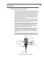
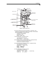
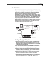
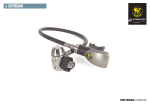
Valco Instruments Co. Inc. Pulsed Discharge Detector Models D-3-I-HP and D-3-I-7890 Instruction Manual Rev 1/15 North America, South America, and Australia/Oceania contact: Valco Instruments Co. Inc. 800 · 367· 8424sales 713 · 688· 9345tech 713 · 688· 8106fax [email protected] Europe, Asia, and Africa contact:: VICI AG International Schenkon, Switzerland Int + 41 · 41 · 925· 6200phone Int + 41 · 41 · 925· 6201fax [email protected] This page intentionally left blank for printing purposes Table of Contents Introduction Description and Operating Principles ............................................................ 1 Safety Notes and Information ........................................................................ 2 Symbols Installation Category Safety Components of the Detector System ............................................................. 3 System Requirements Components not Included with the Detector System ..................................... 4 System Purity ................................................................................................ 4 Gas Specifications ......................................................................................... 5 Installation General Precautions ...................................................................................... 6 Checking the Firmware Version Agilent 6890 GC ..................................................................................... 6 Agilent 7890 GC ..................................................................................... 6 Mounting the Detector .................................................................................... 6 Installing and Configuring the FID Logic Board Agilent 6890 GC ..................................................................................... 8 Agilent 7890 GC ..................................................................................... 8 Gas Connections .......................................................................................... 11 Installing and Purging the Gas Regulator ...............................................11 Installing and Purging the Helium Purifier .............................................. 12 Connecting the Discharge Gas to the Detector ......................................12 Initial Power-Up ............................................................................................. 13 Capillary Column Connection ........................................................................ 14 Packed Column Connection ..........................................................................14 Testing for Leaks ........................................................................................... 15 Mode Selection and Setup Helium Ionization Mode ................................................................................. 16 Selective Photoionization Mode ....................................................................16 Troubleshooting ................................................................................................... 18 Warranty ............................................................................................................. 20 Detector Performance Log ...................................................................................21 This page intentionally left blank for printing purposes 1 Introduction Description and Operating Principle The D3 is a non-radioactive pulsed discharge ionization detector (PDID), with models available for “plug and play” installation on the Agilent 6890 or 7890 GC. A schematic representation of the detector is shown in Figure 1. The D3 utilizes a stable, low power, pulsed DC discharge in helium as the ionization source. Elutants from the column, flowing counter to the flow of helium from the discharge zone, are ionized by photons from the helium discharge above. Resulting electrons are focused toward the collector electrode by the two bias electrodes. The principal mode of ionization is photoionization by radiation arising from 1 + the transition of diatomic helium He2(A ∑ u ) to the dissociative 2He(1S1) ground state. This is the well-known Hopfield emission. The photon energy from the He2 continuum is in the range of 13.5 eV to 17.7 eV. The D3 is essentially non-destructive (0.01 - 0.1% ionization) and highly sensitive. The response to organic compounds is linear over five orders of magnitude with minimum detectable quantities (MDQs) in the low picogram range. The response to fixed gases is positive (the standing current increases), with MDQs in the low ppb range. Detector response is universal except for neon, which has an ionization potential of 21.56 eV. Since this potential is close to the energy of the He* metastable (19.8 eV) but greater than the photon energy from the He2 continuum, neon exhibits a low ionization efficiency and low detector response. When a dopant is added to the discharge gas, the D3 also functions as a selective photoionization detector. (Suitable dopants include Ar for organic compounds, Kr for unsaturated compounds, or Xe for polynuclear aromatics.) GROUND PIN DISCHARGE REGION HELIUM INLET HIGH VOLTAGE SAPPHIRE INSULATORS CAPILLARY COLUMN COLLECTOR ELECTRODE VENT COLUMN INLET Figure 1: Schematic of the D-3 detector Introduction 2 Safety Notes and Information Symbols ATTENTION Refer to the manual. Installation Category This equipment has been designed for installation category (overvoltage category) II, pollution degree 2. It has been approved for use only in heavy industrial environments and may not be used in the residential, commercial, or light-industrial environment. Safety This instrument left the factory in a safe condition. This instruction manual contains important information and warnings which must be followed by the user to insure safe operation and to retain the instrument in a safe condition. Use only with an approved mains supply cord having a rating of 2A, 250V, or greater. Do not use this equipment in a manner not specified herein. CAUTION: During normal operation, the detector produces ultraviolet energy (UVA, UVB), some of which may be emitted. Do not watch the arc without eye protection. Introduction 3 Components of the Detector System Components of the detector system are listed in Table 1 below. Check the contents of the packages to verify that everything is present. Contact the factory if anything is missing or damaged. (NOTE: damaged shipments must remain with the original packaging for freight company inspection.) Introduction 4 System Requirements Components Not Included with the Detector System • Helium (99.999% purity) and other support gases • Ultra high purity grade gas pressure regulator with stainless steel diaphragm • Any special adapters required for connection to the gas regulator • SS tubing to go from gas supply to GC • Flow measuring device System Purity Discharge/Carrier Gas Considerations The performance of the detector is adversely affected by the presence of any impurities in the gas streams (carrier, discharge, or dopant). We recommend that a quality grade of helium 5.0 (99.999% pure or better) be used at all times. Major gas suppliers offer research grade helium (99.9999% pure) which is particularly low in fixed gas impurities and should give good results in a clean system, but even the highest quality carrier gas may contain some water vapor and fixed gas impurities; hence a helium purifier is included as part of the detector system. The discharge gas should always be run through the helium purifier. Whenever a new batch of discharge gas is received, we recommend performing a blank GC analysis of the gas in the PDHID mode to detect and identify the presence of any impurities. Gas purity requirements are specified on the next page. Tubing Standards of cleanliness that are suitable for many GC applications may be totally inadequate for the sensitive PDHID/PDPID work. All surfaces that contact the gas stream must be glass or stainless steel. Do not use copper tubing or brass fittings. All tubes must be thoroughly cleaned and baked before use. Flow Controllers The use of valves or flow controllers in which the gas stream is exposed to any polymer-based packing or lubricating material is to be particularly avoided. Pressure Regulators We recommend commercial “ultra-pure” grade regulators with stainless steel diaphragms. Regulators with diaphragms made of neoprene or other elastomers should never be used. Introduction 5 Gas Specifications Detector Mode PDHID Ar-PDPID Discharge gas Helium 2% Ar in He Carrier gas Helium * Kr-PDPID Xe-PDPID 1.5% Kr in He 0.8% Xe in He ** ** ** Any gas including He which has an ionization potential greater than 12 eV ** Any gas including He which has an ionization potential greater than 11 eV Purity Specifications • Helium (discharge and carrier gas) must have a minimum purity of 99.999%, with < 20 ppm Ne impurity. For trace analysis of fixed gases, we strongly recomment 99.9999% purity He with < 0.5 ppm Ne. • Ar-PDPID mode: • Kr-PDPID mode: • Xe-PDPID mode: 2% ± 0.2% Ar in 99.999% He balance 1.5% ± 0.1% Kr in 99.999% He balance 0.8% ± 0.2% Xe in 99.999% He balance 6 Installation General Precautions • Do not use plastic/polymer or copper tubes for gas handling and interconnectons. Use only stainless steel tubing with Valco gold-plated ferrules. • Do not turn the discharge power on until the helium discharge gas is flowing through the detector. • Do not shut off or disconnect the discharge gas when the detector is hot, even if the GC is turned off. • Do not turn on the GC during detector installation. Checking the Firmware Version Agilent 6890 GC 1. Push <Options> and scroll down to select Diagnostics. Press <Enter>. 2. Select Instrument status, and press <Enter>. 3. Scroll down to read Version A.0x 0x. Successful operation of the D3-I-HP requires either 6890 firmware version A.02.12 or higher or the GC’s FID pneumatic control (EPC). If the EPC is used, all it does is provide the detector title, which remains FID. Agilent 7890 GC When the GC is first powered on, the display will read: Agilent 7890 GC A.0x.0x Power on successful If the instrument is already on and displaying other information, push <Status> and then <Clear> to display the message shown above. How do they know if they have a problem related to firmware version? Will they get some message about incompatibility? The second line is the firmware version. Successful operation of the D3 requires 7890 firmware version A.01.05 or higher. If you experience problems, contact Agilent technical support and request a firmware version compatible with Channel Partner detectors. If you are running ChemStation, please check with Agilent to determine that your version is compatible with Channel Partner detectors. A software upgrade may be required. Mounting the Detector 1. Place the D3 on the top of the GC in either the front or back detector position (Figure 2), and tighten the four captive Torx T-20 screws in the detector pallet. (Figure 3) 2. Connect the high voltage cable to the pulser module. The electrometer and heater cables will be connected after the FID logic board is installed. Installation 7 Agile A 7890 GC s logie chno nt Te MODEL D3 DETECTOR m Syste Figure 2: A D3 detector in the “Back” position on a 7890A CAPTIVE SCREWS (4) DISCHARGE GAS INLET (30 mL/min@60 psi) VENT HEATER/SENSOR CABLE TO D3 PULSER MODULE (PD-M2) HIGH VOLTAGE CABLE ELECROMETER RIBBON CABLE COLUMN INLET CAPILLARY COLUMN ADAPTER (Packed column adapter shown on page10) TO FID LOGIC BOARD Figure 3: Mounting and connecting the detector Installation 8 CAUTION: A D-3-I-HP will not work on a 7890 GC, and a D-3-I-7890 will not work on a 6890. If you are not sure which model you have, call the VICI detector department with the detector serial number. Installing and Configuring the FID Logic Board Agilent 6890 GC (units without EPC) The D3 uses the electrometer portion of the Agilent FID logic board, which must be configured to ignore the ignitor circuit. HEATER/SENSOR CABLE CONNECTOR 1. Plug the FID logic board into the GC main board at the location corresponding to the detector mounting position (front or rear) which you intend for the D3. (Refer to the GC manual as required.) Tighten the detector card screw. (Figure 4) FID BOARD SCREW FID LOGIC BOARD ELECTROMETER CABLE CONNECTOR 2. Connect the heater/sensor cable to the main board and the electrometer cable to the interface board. 3. Push <Config> and scroll down to select Instrument. Press <Enter>. 4. Select F det: FID (for front position) or R det: FID (for rear position) and push <.><.><Mode/Type>. 5. Select Electrometer and press <Enter>. Figure 4: 6890 FID board To switch back to standard FID mode, repeat the procedure and slect FID on the last step. Agilent 7890 GC 1. Refer to the GC manual for instructions on removing access panels. Install the FID logic board as illustrated in Figure 5, at the location corresponding to the detector mounting position (front or back). Secure the thumb screw at the top right corner. 2. Connect the heater/sensor cable and the electrometer ribbon cable to the FID logic board as shown in Figure 5 . 3. Connect the appropriate F-DET (front) or B-DET (back) cable to the logic board. The AUX DET1 cable is not be used with the VICI D3 detector. 4. Press <Options>, and use the scroll keys to select Keyboard & Display and press <Enter>. 5. Scroll to select Hard Configuration Lock. Set it to OFF by pressing the <Off/No> key. Installation 9 MODEL D3 IN BACK POSITION FRONT OF 7890 HEATER CABLE CONNECTIONS THUMBSCREW FID LOGIC BOARD FOR FRONT POSITION ELECTROMETER CABLE CONNECTIONS FID LOGIC BOARD FOR BACK POSITION B-DET CABLE CONNECTION F-D ET B-DET F-DET CABLE CONNECTION Figure 5: 7890 FID logic board 6. Press the <Config> key, then press <Back det> or <Front Det>, corresponding to the location where the PDD will be installed. For this example we will select Back Det. The display will read: Configured (or Unconfigured) Ignore ready = False [B-DET] = (Signal) (FID) 7. Press <Mode/Type>. The display will read: CONFIGURE BACK DETECTOR Remove Module < (cursor is here) 8. Press <Enter> to clear the existing configuration. The display will read: CAUTION: Instrument power must be turned off and back on for set point to take effect. 9. Do not turn off the GC; instead press <Enter>. The display will read: CONFIGURE BACK DETECTOR Unconfigured: < (cursor is here) [B-Det] = (Signal) (FID) [EPC4] Not Found [A-Det2] Not Found 10. Press <Mode/Type>. The display will read: CONFIGURE BACK DETECTOR CPDET FID, No Htr, No EPC < (cursor is here) CPDET FID, Htr, No EPC Installation 10 11. Scroll to select the second line and press <Enter>. The display will read: CAUTION: Instrument power must be turned off and back on for set point to take effect. 12. Do not turn off the GC; instead press <Enter>. The display should read: CONFIGURE BACK DETECTOR Configured: Channel Partner Ignore Ready = False [B-det] = (Signal) (FID) 13. Turn off the GC and power it back up. Verify the configuration by pressing <Back Det>. The display should read: Back detector (CP) Temperature xx. .x Output xxxx Installation 11 Gas Connections Remember these three points discussed earlier: (1) all surfaces that contact the gas stream must be glass or stainless steel; (2) do not use copper tubing or brass fittings; and (3) all tubes must be thoroughly cleaned and baked before use. The installation instructions below assume that the detector discharge gas will be supplied from a nearby cylinder of helium of the proper purity. If your installation is different, you may need to modify the instructions appropriately. A number of Valco fittings have been supplied in the fittings kit to handle different situations. Since the distance from the helium supply to the GC varies from installation to installation, we do not supply tubing to go from that point to the GC. Figure 6 illustrates gas connections for the PD-D3-I detector system. Since the distance from the helium supply to the GC varies from installation to installation, we do not supply tubing for that purpose. TEE (ZT1) HELIUM PURIFIER TGA-R-30F60P RESTRICTOR (30 mL/min minimum) DISCHARGE GAS (99.999% He) DISCHARGE GAS INLET VENT EPC HPM COLUMN INLET COLUMN ELECTRONIC PNEUMATIC CONTROL VICI MINIATURE HELIUM PURIFER INJECTOR GAS CHROMATOGRAPH Figure 6: Gas connections for a PD-D3-I system Installing and Purging the Gas Regulator 1. Make sure the on/off valve on the helium cylinder is completely closed. Screw the CGA fitting nut of the regulator into the helium cylinder. Go beyond finger-tight, but do not tighten the nut all the way – some leakage is required for the purging operation. 2. Turn the output pressure regulating knob completely counterclockwise. 3. Open the cylinder on/off valve slightly and quickly close it again. 4. Adjust the tightness of the regulator connecting nut to allow a pressure reduction of ~690 kPa/sec (100 psi/sec). With a new bottle, the gauge should start out at about 14 MPa (2000 psi). 5. When the pressure drops into the 1.4 - 3.4 MPa (200 - 500 psi) range, open the cylinder on/off valve slightly and quickly close it again. 6. Repeat Step 5 eight or ten times to be certain that all the air is purged. On the final purge, tighten the regulator connecting nut very securely as the pressure approaches the 2.1 - 3.4 MPa (300 - 500 psi) range. Installation 12 7. Open the cylinder valve to pressurize the regulator once again. Close the valve and observe the needle of the high pressure gauge for 15 minutes. If it doesn’t move, there is no critical leak on the high pressure side of the regulator. CAUTION: Never use leak detecting fluids on any part of this system. Installing and Purging the Helium Purifier 1. If the pressure regulator has a 1/8" male cone-type outlet port, install the Valco 1/8" external to 1/16" internal reducer (EZR21); if it has a 1/4" male cone-type outlet port, install the Valco 1/4" external to 1/16" internal reducer (EZR41). For other regulator outlet fittings, a wide variety of Valco adapters is available. 2. Remove the cap from the inlet tube of the Valco helium purifier and insert the tube fitting into the 1/16" reducer port. (Keep the outlet tube capped.) Use a 1/4" wrench to turn the nut one-quarter turn past the point where the ferrule first starts to grab the tubing. Do not remove the fitting. When made up properly, it should be leak-tight. 3. Turn the output pressure regulating knob clockwise until the gauge registers 345 KPA (50 psi). 4. Allow five minutes for equilibration, then turn the regulating knob all the way counterclockwise. 5. Observe the needle of the output pressure gauge for 15 minutes. There will be a slight initial drop, but if it doesn’t move after that, consider that all the connections are tight. 6. If necessary, use an electronic leak detector to locate any leaks. If a leak detector is not available, tighten all the fittings (including the output pressure guage), and repressurize the system for another test. CAUTION: Never use leak detecting fluids on any part of this system. 7. Upcap the outlet tube of the purifier and purge the system for 15 to 30 minutes at 60 - 80 mL/min to eliminate air from the purifier getter material. Connecting the Discharge Gas to the Detector 1. Connect the discharge gas source to restrictor TGA-R-30F60P, and connect the restrictor to the detector inlet. 2. Connect a flow measuring device to the vent and adjust the helium pressure to obtain a flow of ~30 mL/min. Installation 13 Initial Power-Up CAUTION: Always make sure that discharge gas is flowing before heating and powering up the detector. 1. Before installing the column, set the gas flow to 30 ml/min (measured at the detector vent). Let it flow for 15 minutes so that all air is purged from the helium purifiers. 2. Plug in the helium purifiers and turn on the GC. 3. Set the detector temperature to 100°C and allow time for the detector and helium purifiers to reach the set temperature. 4. Plug the 24 VDC output from the power supply (I-23569-1) into the pulser module (PD-M2). 5. Plug the power supply cord to a 100 - 250 VAC source, and look through the hole in the detector housing to see if the discharge is on. CAUTION: During normal operation, the detector produces ultraviolet energy (UVA, UVB), some of which may be emitted. Do not watch the arc without eye protection. 6. Check the standing/background current, and record it in the Detector Performance Log on the last page of this manual. Optimum range is 600 - 2000 pA at 100°C. Lower current indicates a clean, leak-free system. 7. The recommended detector temperature is 20°C above the column temperature, with a minimum of 100°C. Set the detector to the operating temperature required for the intended analysis. When the detector has reached the set temperature, read and record the standing current. 8. Install the column as illustrated on page 11, leaving the oven at ambient temperature. Start carrier flow, then read and record the standing current. The difference between this reading and the one previous is the ionization of the combined impurities in and eluting with the carrier gas. The smaller the difference, the better the quality of the gas exiting the column. 9. Set the column oven to the temperature required for the intended analysis. When the oven reaches the set temperature, read and record the standing current. The difference with the previous reading is the ionization of the column bleed. The smaller the difference, the better the column is conditioned. NOTE: Some stationary phases will have a higher bleed than others, but are still suitable for this detector. However, the lower the bleed, the lower the chances of contaminating the detector cell. From this point, the standing current should be observed and logged after any system change. In addition, logging the standing current (with and without the column) on a regular basis is an effective monitor of system integrity (leaktightness and cleanliness). We also recommend tracking the internal standard (quantity on column/area count) for sensitivity continuity. Installation 14 Capillary Column Connection If the capillary column adapter is installed in the column inlet: 1. Make a mark on the column 10.3 cm from the end. COLUMN INLET 10.3 cm CAPILLARY COLUMN ADAPTER (IZERA1.5) 2. Remove the knurled nut and plug from the capillary column adapter in the column inlet at the bottom of the detector. (Figure 3) Slide the nut over the end of the column, followed by the appropriate column ferrule (FS.4 or FS.5, or ZF.5V for megabore). COLUMN FERRULE 3. Seat the ferrule in the detail of the column adapter and begin sliding the column through the capillary column adapter and into the column inlet. NUT CAPILLARY COLUMN 4. Get the nut started on the threads and tighten it until you feel it contact the ferrule, then back off half a turn. Slide the column into the column inlet until the mark is flush with the surface of the knurled nut, and secure the column in the adapter by tightening the knurled nut finger tight only. If the capillary column adapter has been removed, reinstall it: 1. Unscrew the liner as far as it will go, then screw the fitting body into the column inlet fingertight. 2. While using a 1/8" wrench to prevent rotation of the liner (the part with the seat for the column ferrule), use a 1/4" wrench to tighten the body of the adapter until the ferrule has sealed. The liner will deform if it rotates. 3. Proceed to Step 1 above. Packed Column Connection COLUMN INLET 8.7 cm PACKED COLUMN ADAPTER (I-23642-D3) To prevent detector contamination, we strongly recommend disconnecting the column from the detector during column bakeout procedures. The D3 is optimized for packed columns. The column tubing must be thoroughly cleaned and baked before the column is packed. Even when the best care is taken in column tubing cleaning and in the support and stationary phase selection, a new column will often bleed compounds, resulting in a considerable increase in the detector baseline. This initial bleed will usually be reduced to acceptable levels after the column is conditioned with clean carrier gas flow for several hours at the recommended bakeout temperature. 1. Loosen and remove the knurled nut and plug of the capillary column adapter, (or remove the column ferrule and the column if one has been installed). PACKED COLUMN 2. Use a 1/8" wrench to hold the liner – that part of the adapter in which the column ferrule sits. While the 1/8" wrench keeps the liner from rotating, use a 1/4" wrench on the fitting body to loosen the adapter 1/2 turn. Installation 15 3. Set aside the 1/8" wrench and completely remove the adapter from the column inlet. 4. Screw the packed column adapter into the column inlet by hand. Exercise caution, as the tip of the adapter is very fragile. Then tighten the adapter with a 1/4" wrench, using an additional wrench on the flats of the column inlet to support the detector. 5. Connect the 1/8" column to the packed column adapter with the EZRU21 reducing union supplied in the fittings kit. Testing for Leaks It is critical for the system to be leak-tight, and an additional check at this point can save many headaches later on. To test for leaks: 1. Cap the tube and pressurize the entire system with helium to 138 kPa (20 psi). 2. If the system does not hold pressure, check all the fittings with an electronic helium leak detector. DO NOT use leak detecting liquids. 3. Tighten fittings as required. 16 Mode Selection and Setup Helium Ionization Mode Since the PDHID mode provides a better indication of the cleanliness and the integrity (leak tightness) of the system, that mode is utilized for initial testing and startup. If the system is operating according to the parameters described thus far, it is ready for operation in the PDHID mode. Selective Photoionization Mode To maximize detector lifetime, turn off the discharge power when the GC is not actually analyzing samples. This is especially important in the Ar/Kr PID mode. Since the pulsed discharge detector is essentially a windowless helium photoionization detector, changing the discharge gas from pure helium to helium doped with argon, krypton, or xenon changes the discharge emission profile. This results in a change in the photon energy due to additional resonance atomic emissions and diatomic emissions from the rare gas added. Thus a single detector can be operated in any of the three photoionization detector (PID) modes: Ar-, Kr-, or Xe-PID. Doped helium is used rather than other pure gases in order to retain the benefits of the helium: namely, its transparency for Ar, Kr, an Xe resonance radiation and its efficient cooling of the electrodes. Any problems associated with the presence of a window between the photon source and the ionization chamber are eliminated. In most applications involving current commercial PIDs, analyte condensation and decomposition on the window attenuate the lamp energy, necessitating frequent cleaning and recalibration. Custom gas blends for the pulsed discharge detector are available from leading gas suppliers at special prices. Alternatively, they may be formulated on the spot by using appropriate fixed restrictors to mix appropriate amounts of pure helium and pure dopant through a tee. Since all gas streams must pass through a Valco purifier, the second option requires an additional purifier for each dopant. This may still be more cost effective than requesting a custom blend of the more expensive Kr or Xe; since the typical flow rate required for the pure dopant rare gas is about 0.3 - 1 mL/min, a small lecture bottle can last for a long time. In either case, the total discharge gas flow rate should be the same as specified in “Connecting the Discharge Gas to the Detector” on page 12. Mode Selection and Setup 17 Ar-PDPID Changing the discharge gas from helium to a mixture of 2% argon in helium changes the photon energy level from the 17 - 13.5 eV range to the 11.8 - 9.8 eV range. The argon emission consists of resonance radiation at 11.8 eV and 11.6 eV and the diatomic Ar2 emission in the range of 9.2 - 10.3 eV. Except for fixed gases and a few organic compounds like CH4 (IP = 12.5 eV), CH3CN (IP = 12.2 eV) and some fluro-chloro hydrocarbons, the majority of organic compounds have ionization potentials lower than 11.8 eV. Thus the Ar-PDPID is nearly universal, like the flame ionization detector, but without the risks associated with the presence of an open flame and hydrogen. Kr-PDPID The recommended proportion is 1.4% Kr in He as the discharge gas. The krypton emission consists principally of resonance lines at 10.6 eV and 10.1 eV. The Kr-PDPID can detect compounds with IP < 10.6 eV, which includes unsaturated and cyclic hydrocarbons, alcohols, aldehydes, organic acids, esters, etc. Xe-PDPID The recommended proportion is 0.8% Xe in He as the discharge gas. The xenon emission consists principally of resonance lines at 9.6 eV and 8.4 eV, and can detect compounds with IP < 9.6, like aromatics, ethers, alcohols, aldehydes, etc. In addition to the specific compounds named in the three paragraphs above, certain important inorganic compounds like ammonia, hydrogen peroxide, arsenic trichloride, hydrogen sulfide, arsine, phosphine, nitric oxide, carbon disulfide etc. can be selectively detected using the appropriate photoionization mode. Each dopant gas requires an additional helium purifier, which must be purged and conditioned in the same manner as the purifier installed on the discharge gas supply. If you are using more than one dopant, we recommend use of a Valco multiposition stream selection valve so that no fittings have to be disconnected. Not only is this convenient, it keeps the system closed, minimizing chances of contamination. When changing from one dopant to another, allow at least one hour for the old gas to be purged from the system. 18 Troubleshooting High Background Current The detector isn’t leaking. Check for column bleed and/or leaks in the GC setup. Baseline current falls to normal range (< 2000 pA) Disconnect the column and cap the column inlet Pink Check discharge color Baseline current is still high (> 2000 pA) Baseline current falls to normal range (< 2000 pA) Baseline current is still high (> 2000 pA) Consult Valco Baseline current falls to normal range (< 2000 pA) Purple/ blue Do a hydrogen leak test (described on next page) Leaks in the fittings of the PDD plumbing Tighten leaking fittings Leaks inside the detector cell itself Consult Valco No detectable leaks. Possible bad carrier gas or empty He bottle. Install a new bottle. Baseline current is still high (> 2000 pA) Consult Valco Baseline current falls to normal range (< 2000 pA) Baseline current is still high (> 2000 pA) Consult Valco Low Sensitivity Check background current with column removed and column inlet plugged High background current (> 2000 pA) Normal background current (£ 2000 pA) Refer to Troubleshooting: High Background Current Reinstall column and check background current Sensitivity is in acceptable range Background current remains high Remove column and condition it, then run a sample Sensitivity is still too low Run a sample Sensitivity is in acceptable range Background current increases Check column inlet for leaks. Tighten fittings. Background current drops to normal range Background current remains in normal range Check column position according to drawing on p. 14, and run a sample. Sensitivity is in acceptable range Sensitivity is still too low Sensitivity is still too low Remove column and bake detector at 300°C for four hours. Install column and run a sample. Sensitivity is in acceptable range Sensitivity is still too low Consult Valco No Peaks If the background current is stable but there are no peaks: 1. Check column flow. 2. Check the column insertion position (10.3 cm for capillary columns, 8.7 cm for packed columns). 3. If there are still no peaks, check to make sure that the GC is actually making an injection. 4. If there are still no peaks, consult Valco. Troubleshooting 19 High Noise Level If the noise lievel is high: 1. See if it improves with the GC fan turned off. 2. Check the column insertion position (10.3 cm for capillary columns, 8.7 cm for packed columns.) 3. If the noise level is still high, do a hydrogen leak test, described below. 4. If there are no leaks found, or leaks are found and repaired and the noise level is still high, consult Valco. Performing a Hydrogen Leak Test A hydrogen leak test allows you to pinpoint loose fittings and leaks inside the detector. 1. Connect a length of plastic tubing to a regulated hydrogen bottle. Establish a flow of 5-10 ml/min. 2. Hold the hydrogen outlet tube at a fitting connection for ten seconds while monitoring the baseline. 3. Tighten the fitting and test it again, repeating as necessary until every connection has passed the ten second test. 4. Hold the hydrogen outlet close to the detector. (Do not insert the tube into any detector holes.) If a leak in the detector is indicated, contact Valco. 20 Warranty This Limited Warranty gives the Buyer specific legal rights, and a Buyer may also have other rights that vary from state to state. For a period of 365 calendar days from the date of shipment, Valco Instruments Company, Inc. (hereinafter Seller) warrants the goods to be free from defect in material and workmanship to the original purchaser. During the warranty period, Seller agrees to repair or replace defective and/or nonconforming goods or parts without charge for material or labor, or, at the Seller’s option, demand return of the goods and tender repayment of the price. Buyer’s exclusive remedy is repair or replacement of defective and nonconforming goods, or, at Seller’s option, the repayment of the price. Seller excludes and disclaims any liability for lost profits, personal injury, interruption of service, or for consequential incidental or special damages arising out of, resuiting from, or relating in any manner to these goods This Limited Warranty does not cover defects, damage, or nonconformity resulting from abuse, misuse, neglect, lack of reasonable care, modification, or the attachment of improper devices to the goods. This Limited Warranty does not cover expendable items. This warranty is VOID when repairs are performed by a nonauthorized service center or representative. For information about authorized service centers or representatives, write Customer Repairs, Valco Instruments Company, Inc, P.O. Box 55603, Houston, Texas 77255, or phone (713) 688-9345. At Seller’s option, repairs or replacements will be made on site or at the factory. If repairs or replacements are to be made at the factory, Buyer shall return the goods prepaid and bear all the risks of loss until delivered to the factory. If Seller returns the goods, they will be delivered prepaid and Seller will bear all risks of loss until delivery to Buyer. Buyer and Seller agree that this Limited Warranty shall be governed by and construed in accordance with the laws of the State of Texas. The warranties contained in this agreement are in lieu of all other warranties expressed or implied, including the warranties of merchantability and fitness for a particular purpose. This Limited Warranty supercedes all prior proposals or representations oral or written and constitutes the entire understanding regarding the warranties made by Seller to Buyer. This Limited Warranty may not be expanded or modified except in writing signed by the parties hereto. 21 Detector Performance Log In addition to the occasions indicated in the Comments area of the table below (see Initial Power-Up, page 13), the standing current should be observed and logged after any system change. Logging the standing current (with and without the column) on a regular basis is also an effective monitor of system integrity (leaktightness and cleanliness). To check sensitivity continuity, we recommend tracking the internal standard (quantity on column/area count). Additional log pages can be downloaded from the support/manuals section of www.vici.com. Detector Model: Date D-3-I- Operator Serial Number: Comments Date of purchase: Column Detector Noise temp temp level (°C) (°C) Initial power-up (IPU) IPU, detector to analysis temp Ambient IPU, column installed IPU, column to analysis temp 100 Sample Standing current (pA)