1
Chapter 10 Installation and Wiring
10.5 Communication Interface Connection Method
10.5.1 RS-232C Interface (XBL-C21A)
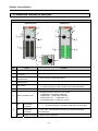
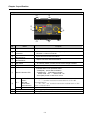
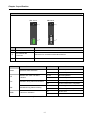
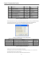
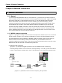
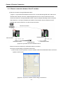
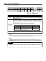
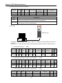
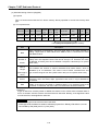
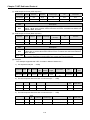
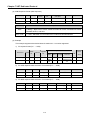
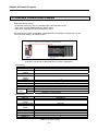
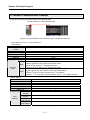
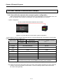
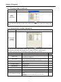
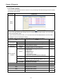
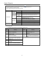
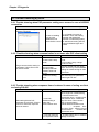
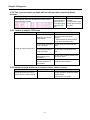
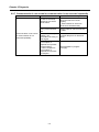
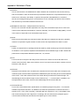
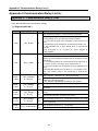
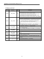
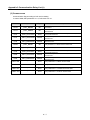
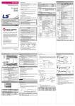
Channel RS-232C uses 9-pin connector (Female) for communication with external devices. The
names and functions of pins and data directions are as shown in the figure below.
Pin No. Name
Contents
Signal Direction
(Cnet I/F module
↔ external device)
Description
1
2
3
CD Carrier Detect
RxD Received Data
TxD Transmitted Data
Reports carrier detection of DCE to DTE
Received data signal
Transmitted data signal
4
DTR
Data Terminal
Ready
Reports ready communication of DTENote1 to
DCE Note2
5
6
7
8
9
SG
DSR
RTS
CTS
RI
Signal Ground
Data Set Ready
Request To Send
Clear To Send
Ring
Ground line for signal
Reports ready communication of DCE to DTE
DTE asks DCE to send data
DCE asks DTE to send data
Reports ringing tone received from DCE to DTE
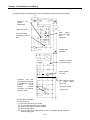
[Figure 10.5.1] RS-232C 9-pin Connector Standard
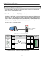
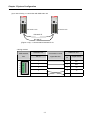
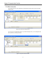
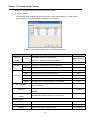
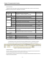
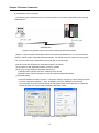
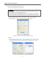
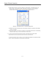
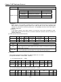
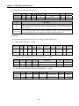
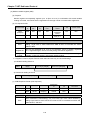
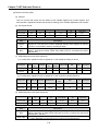
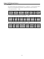
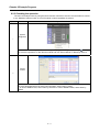
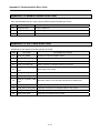
Channel RS-232C can communicate with external devices directly and also with remote communication
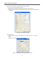
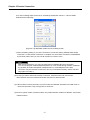
devices using modem. When connecting modem, communication type of RS-232C must be set to
‘modem’ with XG-PD, and when not using modem, it must be set to null modem
Notes
[Note1] DTE: Data Terminal Equipment (Cnet I/F module)
[Note2] DCE: Data Communication Equipment (external modem)
10 −18