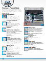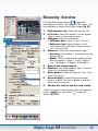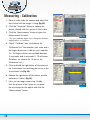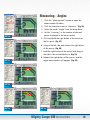
1
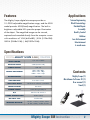
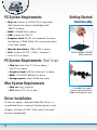
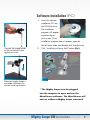
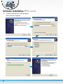
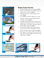
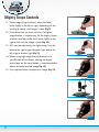
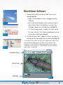
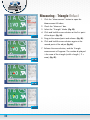
Mighty Scope 5M
Instruction Manual
aveninc.com
Contents
Features 2
Specifications 2
Contents 2
PC System Requirements 3
Driver Installation Procedure 3
Getting Started 3
Software Installation (PC)
4
Mighty Scope Controls
6
MacroViewer Software 8
Function Key Lists
9
Compare 10
Video Setup 12
Preview picture mode 13
Measuring
14
Software Installation (Mac)
22
MacroViewer Software (Mac)
23
24
Function Key Lists
Compare 25
Video Setup 26
Measuring
27
FAQ34
1
Features
Applications
The Mighty Scope digital microscope provides a
10~200X adjustable magnification range, and the 500X
model provides 500X(fixed) magnification. The built-in
brightness adjustable LEDs provides proper illumination
of the object. The magnified image can be viewed,
captured and recorded directly from the computer screen
with resolutions of: VGA (640x480) | XGA (1024x768)
QXGA (2048x1536) | 5M(2592x1944).
Science Engineering
Work Dermatology
Detailed Repair
Assembly
Quality Control
Hobbies
Law Enforcement
Entertainment
& much more
Specifications
Digital Mighty Scope 5.0M |10x-200x
Image Sensor
1/4” Color CMOS
Effective Pixels
5.0M (2592x1944)
Signal Output
USB 2.0
Frames Per Second
640 x 480: 30fps
1024 x 768 : 30fps
2048 x 1536: 15fps
Magnification
10x~200x
Gain Control
Auto Gain Control
Snap Shot Mode
Hardware & Software controllable
White Balance
Automatic
Power Source
5VDC through USB port
O/S
Windows XP, Vista & 7
Power Consumption
260mA (AVG)
LED Light Type
6 White LEDs
Working Distance
At 10x, 112mm | At 20x, 42mm
At 30x, 19mm | At 40x, 8.5mm
Contents
Mighty Scope (1)
MicroViewer Software CD (1)
User manual (1)
Stand (1)
Mighty Scope 5M Instruction Manual
2
PC System Requirements
•Chip set: Pentium 4 3.0GHz CPU or equivalent,
AMD Phenom II or above, Northbridge Intel®
Getting Started
Stand Assembly
i945GZ or above
•RAM: 1024MB DDR or above
•USB: At least one USB 2.0
•Graphics Card: 2D/3D with Hardware Transform
and lighting, 512MB VRAM VGA system and at least
16 bit color support
•Monitor Resolution: 1280x1024 or above
•o/s: Windows XP SP2 | VISTA | Windows 7
• Direct X 9.0c or above
Screw together vertical
pole and base
PC System Requirements (Dual Scope)
•Chip set: Intel® Core™ 2 Duo or above /
Intel G31 or above
•Graphics Card: NVIDIA® GeForce® 7 or above
•RAM: 1024 DDR2 800MHz or above
•Storage space: at least 30MB free space
Mac System Requirements
•Chip set: Intel® Processor
•o/s: Mac OS X 10.5 or later
Driver Installation
This device supports “Universal Video Class” driver, so
no additional driver is required. Plug the camera in and
Windows (Windows XP SP2, VISTA, and 7) will install
the driver automatically.
3
Assemble the scope’s
2-piece rack and pinion
holder and tighten screw
Software Installation (PC)
1. Insert the software
installation CD into
the CD-ROM drive.
The installation
program will appear
automatically on
your screen. (If the
installation program doesn’t appear, open the
MicroViewer folder and double click AutoRun.exe)
Connect the scope holder
to the vertical post and
tighten set-screw
2. Click “Install MicroViewer 5MP” button (Fig.1).
FIG. 1
Place the Mighty Scope is
the holder and adjust to
desired working distance
**The Mighty Scope must be plugged
into the computer to open and run the
MicroViewer software. The MicroViewer will
not run without a Mighty Scope connected.
Mighty Scope 5M Instruction Manual
4
Software Installation (PC) cont.
3. Install the MicroViewer 5MP program
and restart the computer.
5
Mighty Scope Controls
4. Connect the Might Scope to the computer (Fig. 2).
5. Double Click the [MicroViewer 5MP] software, the
start-up screen will show up (Fig. 3).
6. Place the camera on or above the object to be
FIG. 2
viewed (Fig. 4).
7. Tilt the digital microscope slightly when viewing
the object in order to get more depth of field to
resemble a 3D image (Fig. 5).
8. The Mighty Scope can be used to get the desired
magnification preferred by the user. The closer the
FIG. 3
Mighty Scope is to the object, the larger image will
be and higher magnification (Fig. 6).
9. A clear focused image is obtained by adjusting
the focus knob as well as changing the distance
between the object and the Mighty Scope (Fig. 7).
10.If the image is blurred, adjust the focus knob to the
FIG. 4
right end and view the image of the object in lower
magnification first (Fig. 8).
FIG. 5
FIG. 6
FIG. 7
FIG. 8
Mighty Scope 5M Instruction Manual
6
Mighty Scope Controls
11.When magnifying an object, adjust the focus
knob slightly to the left or right, depending on the
working distance, until image is clear (Fig. 9).
12.If the object has too much relief or if a higher
magnification is unnecessary, lift the Mighty Scope
FIG. 9
a little bit and adjust the focus knob slightly to the
right or left until the image is clear (Fig. 10).
13.LEDs can be adjusted by the light wheel. Turn the
knob to the right to get a brighter light and to the
left to get a dimmer light (Fig. 11).
14.When using high magnification to observe a
FIG. 10
specific area of the object, placing the digital
microscope on the stand holder is recommended to
obtain a clearly focused image (Fig. 12).
15.Use snapshot button to capture an image (Fig. 13).
FIG. 11
FIG. 12
FIG. 13
7
MicroViewer Software
1. Double click the [MicroViewer 5MP] icon on your
desktop (Fig. 14).
• Make sure the Mighty Scope is plugged into the • Key in the Serial Number (which can be found on
USB port.
FIG. 14
the outside of the CD envelope) or just press the
“Evaluate” button for a 30 day free trial (Fig. 15).
• ”TV Card Configuration” window will show up the
first time, click the “OK” button and double click the
MicroViewer 5MP again (Fig. 16).
FIG. 15
2. The MicroViewer 5MP window will show up and you
should see the live image from the Microscope (Fig. 17).
**The MicroViewer 5MP will choose the appropriate video format
automatically by detecting the resolution of the monitor. If the
resolution is 1280x1024 (or above), the default video format is
1024x768. If the resolution is 1024x768(or below), the default
video format is 640x480.
FIG. 16
Function Key
Live zone
List bar
FIG. 17
Mighty Scope 5M Instruction Manual
8
MicroViewer Menu
Snapshot
Take a picture.
(Saved as a BMP file)
Shortcut key: F3
*The max resolution for software
snapshot is 2048x1536.
Zoom in/out
Select the zoom-in and zoom-out
function on a live image or on
captured pictures. The maximum
magnification is 6x. The arrow keys
on the keyboard will move the image.
Shortcut key: +/-
Record
Capture a movie.
(Saved as an AVI video file)
Shortcut key: F4
Compare
Compare a live image with a
picture or video, compare two
pictures or compare two live image
from two microscopes
(Please see the Compare Section for
more detail)
Shortcut key: C
Freeze
Freeze the live image on the screen.
Shortcut key: F
Save clipboard
Copy the live image to the clipboard.
Play
Playback the last recorded video.
Video Setup
The setup window.
(Please see the Video Setup Section for
more detail)
Shortcut key: V
Video Quality
Change the video value for
brightness, contrast and saturation.
Zoom screen
Click “Zoom screen icon” or
double click the live image, it will
switch to full screen mode.
Power off
Close MicroViewer 5MP.
Measurement
Measure lines, circles, angles,
rectangles, triangles or radii.
(Please see the Measurement Section for
more detail)
Shortcut key: M
9
Shortcut key: X
Micro Viewer Comparison Mode
1. Plug two microscope USB cables into the PC USB
ports (Fig. 17).
2. Click the Compare button,
FIG. 17
1.If you close MicroViewer
5MP on compare mode,
it will automatically enter
compare mode next time.
2.The resolution of the 2nd
microscope will change
automatically when you
change the resolution of
the first microscope.
and the compare
window will appear on the screen. The live image
shows in the left zone (Fig. 18).
*For the best results screen resolution
requirement should be at least 1440x900 pixel
3. Click the 2nd Camera button
to show the live
image of the second Mighty Scope.
*The second Mighty Scope only supports
Snapshot, Recording, Preview Image, and Freeze
functions.
4. The compare window also supports dragging any
pictures to the left and right sides to compare two
existing pictures.
5. Click (Go Back button)
or (Compare button) to
return to normal mode.
FIG. 18
FIG. 19
Mighty Scope 5M Instruction Manual 10
MicroViewer – Compare Menu
Camera 2
Enable/Disable the image
of the second microscope.
Snapshot
Take a picture.
Save BMP HR
Combine the two live images
horizontally and take a picture.
*It doesn’t support combining live
image with an existing image.
Save BMP VT
Combine the two live images
vertically and take a picture.
*It doesn’t support combining live
image with an existing image.
Print Dual Camera
Print live images from two
Microscopes.
Save clipboard
Copy the live image to clipboard.
Video Setup
Change the video value for
brightness, contrast and saturation.
Save AVI 2
Capture AVI video files from the
2nd microscope .
Save AVI HR
Combine the two movies
horizontally and save a movie.
* It only supports 640*480 resolution.
11
FAQ
1. W
hy does the combined
picture become distorted
when I preview the image?
A: It will distort the image
because of the ratio on the
screen. Please go to the
saved picture location and
check the picture to see if it
distorted.
2. C
an I print the combined
image full page?
A: Y
es, go into the printer
dialog box and set it to
landscape orientation.
3. D
oes the 2nd microscope
support full-screen function?
A: No, only the 1st microscope
supports full-screen function.
4. C
an I switch the 1st microscope and 2nd microscope?
A: Y
es. Disable the 2nd microscope, and choose the
source in the video setup
window.
Video Setup - Overview
1
2
Click the Setup button
box (Fig. 20).
3
4
for the video dialogue
1. S
ource: User can to choose the image source if
there is multiple microscopes connected to the PC.
2. Video Format: Supports three resolution
options: 640x480 | 1024x768 | 2048x1536.
5
6
*Both the Snapshot and Record format will be changed
3. V
ideo Adjust: Manually change values for
brightness, contrast, and saturation.
4. AVI: Set up the path to save videos.
5. Time Lapse: Check the box and select the
time-lapse rate. (i.e. If you choose”60:1” only one
second of every 60 seconds will be recorded.)
7
9
8
10
11
12
13
14
*If you choose the time-lapse function, please make sure the
recording time is longer than the ratio time. i.e.: Choose “60:1”,
FIG. 20
6. BMP: Set up the path to save pictures.
the real recording time must be longer than 60 seconds.
*If you want to save JPEG files, please check the “Save as JPEG” box.
7. Always On Top: Check this box so the MicroViewer 5MP window is always on the top.
8. Record On The Fly: Record the video immediately when button is pressed.
*If the box isn’t marked, you have to set up the file name and saving location before recording.
9. Play On The Fly: Play the latest video immediately.
*If the box isn’t marked, you have to choose a video file to play.
10. Show Snapshot BMP: After snapshot, the preview window will appear.
11. Use AVI Decompressor: Corrects possible image distortion in Window XP SP2 or
Older.
*DO NOT mark this box if it is Windows XP SP3 or above
12. Use Intel 8xxG/9xxG VGA: Corrects possible image distortion with Intel chip sets.
*The resolution will be limited to 1024x768.
13. HW Snapshot 2592x1944: To save images with maximum resolution of
2592x1944(5MP)when you click the hardware snapshot button.
*It can take 5~6 seconds to save a picture, please not to move the microscope.
14. Full Screen Mode: To Start MicroViewer 5MP in full-screen mode automatically.
• 4:3: Live video zone will remain in a 4:3 aspect ratio. This mode is necessary for the
measurement function.
• FULL: The entire screen will display live video. The aspect ratio may not be correct, so
live images my appear distorted.
• ICON: The Screen will be filled with the MicroViewer 5MP window, so all function
buttons will be visible. In this mode,the video image will be expanded and it is not
correct for the measurement function.
Mighty Scope 5M Instruction Manual 12
Preview – Picture Mode
Drag the picture from the list bar to the live
zone or just double click the picture in the list
bar. The Image will show in the live zone for
editing. (Fig. 21).
Drawing mode
The Drawing mode button opens
Microsoft Paint to draw on the
picture. After editing, close
Microsoft Paint, and the image
will update automatically.
Save file
Click this button to save as a
new file. New file name will be
renamed by date and time.
Shortcut key: S
Compare
Compare a live image with a
picture or video, compare two
pictures or compare two live image
from two microscopes
(Please see the Compare Section for
more detail)
Shortcut key: C
Delete
Click the Delete button to delete
an image or video. If you want to
recover this file, just click Save file
button. To delete files, you can also
left click the picture in the list bar
and drag to the Delete icon.
Shortcut key: D
Print File
Print this picture. Opens printer
dialogue box.
Measurement
Measure lines, circles, angles,
rectangles, triangles or radii.
(Please see the Measurement Section for
more detail)
Shortcut key: M
13
FIG. 21
Zoom in/out
Select the zoom-in and zoom-out
function on a live image or on
captured pictures. The maximum
magnification is 6x. The arrow
keys on the keyboard will move
the image.
Shortcut key: +/-
Go Back
Go back to live mode.
Video Setup
Opens the video setup window.
(Please see the Video Setup Section for
more detail)
Shortcut key: V
Video Quality
Change the video value for
brightness, contrast and saturation.
Measuring -Overview
Click the Measurement button
to open the
measurement window. The image will be frozen. You
can calibrate or measure the frozen image (Fig. 22).
FIG. 22
1
2
3
4
5
1. VGA monitor size: Select the monitor size.
2. H/V ratio: Select the monitor’s correct aspect
ratio to insure correct measurements
3. Calibrate: Adjust the calibration.
• Calibrate axis: X axis /Y axis /X-Y axis.
• Reference Unit: Please select a unit of
measurement for calibration. There are three
units: mm/inch/mil
4. Measure: Choose the measurement type.
• Accuracy: The number is accurate up to nine
decimal points.
• Mode: Select a measurement mode from the
following options: Angle | Circle | Ellipse |
Line | Rectangle | Triangle | 3DotsRadius.
5. Data of the measurement.
6. Remarks: The mode supports Date, Time and
Notes for a measured image.
7. Ruler guides: Check the L-type or Cross if you
want this function.
8. Record history: Record the measurement
actions. It allows the user to delete a record or
clear all history records.
9. Choose the color of the line and words.
*After finishing the measurement, click the Snapshot
button
or save button
to save the
measured picture.
6
7
8
9
Mighty Scope 5M Instruction Manual 14
Measuring - Calibration
1. Place a scale under the camera and adjust the
focus knob until the image is sharp (Fig. 23).
2. Click the “Snapshot” button to capture the
picture, double click this picture in the list bar.
3. Click the “Measurement” button to open the
Measurement Window.
FIG. 23
*You must calibrate again if you change the distance,
magnification, or resolution.
4. Check “Calibrate” box, and choose the
“Reference Unit” that matches your scale and is
the largest dimension visible on your snapshot.
(i.e. The largest dimension available between
3 centimeter and 4 centimeter is 10 millimeter.
Therefore, we choose the 10 mm as the
FIG. 24
“Reference Unit”)
5. Click and hold the right button of the mouse at
the 3 centimeter line and drag the cursor to the
4 centimeter line (Fig. 24).
6. Release the right button of the mouse, and the
calibration is done. (Fig. 25).
7. Now you can begin measuring. Double
click the picture in the list bar or just place
the microscope on the object and click the
“Measurement” button.
15
FIG. 25
Measuring - Angles
1. Click the “Measurement” button to open the
Measurement Window.
2. Click the check box next to “Measure.” (Fig. 26)
3. Select the mode “Angle” from the drop down.
4. Set the “Accuracy” to the number of decimal
FIG. 26
points displayed in the measurement.
5.Click and hold the right button of the mouse at
the first point. (Fig. 27)
6.Drag to the left side and release the right button
of the mouse. (Fig. 28)
7.Hold the right button of the mouse and drag to
the other side counterclockwise. (Fig. 29)
8.Release the right button of the mouse, and the
FIG. 27
angle measurement will appear. (Fig. 30)
FIG. 28
FIG. 29
FIG. 30
Mighty Scope 5M Instruction Manual 16
Measuring - Circle/Ellipse
1. Click the “Measurement” button to open the
Measurement Window.
2. Check the “Measure” box (Fig. 31).
3. Select the“Circle” Mode for circle or “Ellipse”
mode for ellipse.
4. Check the “Cross” function to display crosshairs.
FIG. 31
5. Hold the right button of the mouse at the upper
left of the object (Fig. 32).
*You can aim easily by aligning the X axis cross line
with the top of the object and aligning the Y axis cross
line with the left of the object.
6. Drag to the lower right of the object (Fig. 33).
*You can aim easily by aligning the X axis cross line
with the bottom of the object and aligning the Y axis
cross line with the right of the object.
FIG. 32
7. Release the right button of the mouse (Fig. 34).
• The Circle measurement will display 2
measurements. The “D” means diameter and
the “A” means area.
• The Ellipse measurement will display 3
measurements. The “D1” means X axis
diameter, “D2”means Y axis diameter, and
“A” means area.
FIG. 33
FIG. 34
17
Measuring - Line
1. Click the “Measurement” button to open the
Measurement Window.
2. Check the “Measure” box. (Fig. 35).
3. Select the “Line” Mode.
4. Hold the right button of the mouse at the first
FIG. 35
measurement point. (Fig. 36).
5. Drag the mouse to the sending point of the
measurement (Fig. 37).
6. Release the right button of the mouse,and the
line will appear. The number is the length in the
calibrated units of measure (Fig. 38).
FIG. 36
FIG. 37
FIG. 38
Mighty Scope 5M Instruction Manual 18
Measuring - Rectangle
1.Click the “Measurement” button to open the
Measurement Window.
2.Check the “Measure” box,
3.Select the “Rectangle” Mode (Fig. 39).
4.Click and hold the right button of the mouse at
corner of the object (Fig. 40).
FIG. 39
5.Drag to the lower right of the object (Fig. 41).
6.Release the right button of the mouse and the
rectangle will appear. The number is the area of
the triangle (length x width = area) (Fig. 42).
FIG. 40
FIG. 41
FIG. 42
19
Measuring - Triangle
1. Click the “Measurement” button to open the
Measurement Window.
2. Check the “Measure” box.
3. Select the “Triangle” Mode. (Fig. 43).
4. Click and hold the right button of the mouse at
FIG. 43
the first point of the object. (Fig. 44).
5. Drag to the second point and release. (Fig. 45).
6. Click and hold the right button of the mouse
again at the second point of the object (Fig. 46).
7. Release the right button of the mouse, and the
Triangle measurement will appear. The number
displayed is the area of the triangle (width x
length / 2 = area). (Fig. 47).
FIG. 44
FIG. 45
FIG. 46
FIG. 47
Mighty Scope 5M Instruction Manual 20
Measuring - Radius/Arc
1.Click the “Measurement” button to open the
Measurement Window.
2.Check the “Measure” box.
3.Select the “3DotRadius” Mode (Fig. 48).
4.Click and hold the right button of the mouse at
the first point of the arc (Fig. 49).
FIG. 48
5.Drag to the second point of the arc and release
(Fig. 50).
6.Click and hold the right button of the mouse
again at the second point of the arc , then drag
to the third point of the arc (Fig. 51).
7.Release the right button of the mouse, and the arc
measurement will appear. The “R” means radius ,
“A” means angle, and the “L” means arc (Fig. 52).
FIG. 49
FIG. 50
FIG. 52
21
FIG. 51
Software Installation (Mac)
1. Insert the software installation CD into the
CD-ROM drive. The installation program will
appear automatically on your screen.
2. Click “MicroViewer” icon to install the software.
**The Mighty Scope must be plugged
into the computer to open and run the
MicroViewer software. The MicroViewer will
not run without a Mighty Scope connected.
Mighty Scope 5M Instruction Manual 22
MicroViewer Software (Mac)
1. Double click the [MicroViewer] icon on your desktop
(Fig. 53).
• Make sure the Mighty Scope is plugged into the USB port.
2. The MicroViewer 5MP window will show up and you
FIG. 53
should see the live image from the Microscope (Fig. 54).
**The MicroViewer 5MP will choose the appropriate video format
automatically by detecting the resolution of the monitor. If the
resolution is 1280x1024 (or above), the default video format is
1024x768. If the resolution is 1024x768(or below), the default
video format is 640x480.
Live zone
Function Key
List bar
FIG. 54
23
MicroViewer Menu (Mac)
Snapshot
Take a picture.
Zoom in/out
Select the zoom-in and zoom-out
function on captured pictures.
(Saved as a JPG file)
Record
Capture a movie.
(Saved as an MOV video file)
Compare
Compare a live image with a
picture or video, compare two
pictures or compare two live image
from two microscopes
(Please see the Compare Section for
more detail)
Freeze
Freeze the live image on the screen.
Measurement
Measure lines, circles, angles,
rectangles or triangles
(Please see the Measurement Section for
more detail)
Setup
The setup window.
(Please see the Video Setup Section for
more detail)
Return to live mode
Back to the live mode
Delete
Click the file(picture/video) to
delete, and click the Delete icon.
The file will be erased.
Exit
Close MicroViewer.
Mighty Scope 5M Instruction Manual 24
Micro Viewer Comparison Mode (Mac)
1. Plug two microscope USB cables into the USB ports.
2. Click the Compare button
and the compare
window will appear on the screen. The live image
*For the best results screen resolution
requirement should be at least 1440x900 pixel
3. The live image shows in the left side. You can select
the “Target view” and double click a picture or a
video in the list bar. The file will show up on the
target view.
4. The left side also supports freeze function to
compare two images (Fig. 56).
1
FIG. 55
FIG. 56
25
also supports comparing
two existing pictures.
6. Click the
shows on the left side (Fig. 55).
2
5. The compare window
Compare
button to return to live
mode when viewing
saved images.
Media Setup - Overview (Mac)
1
2
3
4
5
Click the Setup button
box (Fig. 57).
for the media dialogue
1. D
efault Input: Select the desired video source
if there is more than one microscope/camera
connected to the computer.
2. Snapshot Format: Choose which size images
and videos will be saved at: 640x480 or
1280x1024.
*Both the Snapshot and Record format will be changed
3. R
ecording Path: Set up the location to save
videos.
4. Image Path: Set up the location to save images.
5. Image Format: Choose the default image format.
FIG. 57
Mighty Scope 5M Instruction Manual 26
Measuring -Overview (Mac)
Click the Freeze button
to freeze the live image
or double click a image in the list bar. The image
will be frozen. You can only calibrate or measure the
frozen image. Click the Measurement button
to open the measurement dialogue window
(Fig. 58).
1. Calibrate: Check “Calibrate” first before
measurement to set up proper reference points
to measure.
2. Reference Unit: Select the measurement unit
for calibration. There are three different units:
mm/inch/mil
3. Reference Size: Select the unit of measurement
or calibration.
*Using a scale at the chosen magnification
allows for the most accurate measuring.
4. Measure: Check “Measure” to enter
measurement mode.
5. Accuracy: The number of decimal points the
measurement is accurate to. Supports up to nine
decimal points.
6. Draw Mode: Choose the type of measuring:
Angle | Circle | Ellipse | Line | Rectangle |
Triangle.
7. Length/Angle/Area: Shows the latest
measurement data.
8. Add Date Time: Add the date and time
information to the saved image.
9. Add Notes: Add notes to the saved image.
10. Data of the measurement: Records the
measurement actions for the image. It allows
users to delete a record or clear all records.
*After finishing the measurement, click the Save
button
to save the measured picture.
27
1
2
3
4
5
6
7
8
9
10
FIG. 58
Measuring - Calibration (Mac)
1. Place a scale under the camera and adjust the
focus knob until the image is sharp (Fig. 59).
2. Click the “Snapshot” button to capture the
picture, double click this picture in the list bar.
3. Click the “Measurement” button to open the
FIG. 59
Measurement Window.
*You must calibrate again if you change the distance,
magnification, or resolution.
4. Check “Calibrate” box, and choose the
“Reference Unit” that matches your scale
and is the largest dimension visible on your
snapshot. (i.e. The largest dimension available
between 3 centimeter and 3.5 centimeter is 5
FIG. 60
millimeter. Therefore, we choose the 5mm as the
“Reference Unit”)
5. Click and hold the mouse button at the 3
centimeter line and drag the cursor to the 3.5
centimeter line (Fig. 60).
6. Release the mouse button, and the calibration is
complete. (Fig. 61).
FIG. 61
7. Now you can begin measuring. Double
click the picture in the list bar or just place
the microscope on the object and click the
“Measurement” button.
8. Click the
to return to live mode.
Mighty Scope 5M Instruction Manual 28
Measuring - Angles (Mac)
1. Click the “Measurement” button to open the
Measurement window.
2. Change the draw mode to “Angle.“
3. Click the check box next to “Measure.” (Fig. 62)
4. Set the “Accuracy” to the number of decimal
FIG. 62
points displayed in the measurement.
5. Select the mode “Angle” from the drop down.
6.Click the mouse button at the first point. (Fig. 63)
7.Click at the second point or corner of the angle
1
and release the button of the mouse. (Fig. 64)
8.Double click the mouse button at the third point.
(Fig. 65)
9.The measurement of the angle will appear
FIG. 63
on the image as well as in the bottom of the
“Measurement Dialogue Box.“ (Fig. 66)
2
1
FIG. 64
3
2
1
FIG. 66
29
FIG. 65
Measuring - Circle/Ellipse (Mac)
1. Click the “Measurement” button to open the
Measurement Window.
2. Check the “Measure” box (Fig. 67).
3. Select the“Circle” Mode for circle or “Ellipse”
mode for ellipse.
FIG. 67
4. Click and hold the button of the mouse at the
center of the object (Fig. 68).
5. Drag to the outer edge of the object (Fig. 69).
6. Release the mouse button (Fig. 70).
• The Circle measurement will display 2
measurements. The “R” means radius and the
“A” means area.
FIG. 68
• The Ellipse measurement will display 3
measurements. The “Major Axis / Minor Axis
= Area.
FIG. 69
FIG. 70
Mighty Scope 5M Instruction Manual 30
Measuring - Line (Mac)
1. Click the “Measurement” button to open the
Measurement Window.
2. Check the “Measure” box. (Fig. 71).
3. Select the “Line” Mode.
4. Hold the mouse button at the first measurement
point. (Fig.72).
FIG. 71
5. Drag the mouse to the sending point of the
measurement (Fig. 73).
6. Release the mouse button,and the line will
appear. The number is the length in the
calibrated units of measure (Fig. 74).
FIG. 72
FIG. 73
FIG. 74
31
Measuring - Rectangle (Mac)
1.Click the “Measurement” button to open the
Measurement Window.
2.Check the “Measure” box,
3.Select the “Rectangle” Mode (Fig. 75).
FIG. 75
4.Click and hold the mouse button at corner of the
object (Fig. 76).
5.Drag to the opposite corner (diagonally) of the
object (Fig. 77).
6.Release the mouse button and the rectangle will
appear. The number is the area of the triangle
(length x width = area) (Fig. 78).
FIG. 76
FIG. 77
FIG. 78
Mighty Scope 5M Instruction Manual 32
Measuring - Triangle (Mac)
1. Click the “Measurement” button to open the
Measurement Window.
2. Check the “Measure” box.
3. Select the “Triangle” Mode. (Fig. 43).
4. Click and hold the mouse button at the first point
FIG. 79
of the object. (Fig. 44).
5. Drag to the second point and release. (Fig. 45).
6. Click and hold the mouse button again at the
second point of the object (Fig. 46).
1
7. Release the mouse button, and the Triangle
measurement will appear. The number displayed
is the area of the triangle (width x length / 2 =
FIG. 80
2
FIG. 81
3
FIG. 82
33
area). (Fig. 47).
FAQ
Q. After inserting the software installation CD into the CD-ROM drive,
Q. A
fter installing the
MicroViewer 5MP, why
why doesn’t the install start automatically?
A: Due to the computer’s system security, many system’s software
doesn’t the MicroViewer 1.3M
program work?
disables the CD-R/USB Auto run function. Please double click
the CD-ROM drive on your computer, and click the
A: The version you are running
might be out of date. Please
AUTORUN.EXE file.
install the upgrade version of
Q. Why does the image lag after I check the Use AVI Decompressor
MicroViewer 1.3MP by the
following steps:
box on the Video Setup window?
A: The Use AVI Decompressor function doesn’t support Windows XP
• Insert the MicroViewer 5MP
• Click the “Install
CD into the CD-ROM drive.
SP3 or above.
Q. Why is the measurement number incorrect?
MicroViewer 1.3MP”
A: You need to use the Calibrate function on the measurement
button on the installation
window before making a measurement. Also if you change the
program and the latest
focal distance or height of the object you will need to use the
MicroViewer 1.3MP will
Calibrate function again.
install automatically.
Q. Why does the monitor “twinkle” under the measurement mode?
A: Set up the system using the following steps: Start>Control
Panel>Home>System Advanced>Performance>Setting. Deselect
the “Show shadows under windows” and ”Show window contents
Q. I can’t install the MicroViewer
because of the antivirus
software protection. How do
you solve this problem?
A: Your antivirus software may
while dragging.”
quarantine the MicroViewer
Q. Why does the recording file show an error message when I open
because the software thought
it was a virus. Try adding
the time-lapse function?
A: If you open the time-lapse function, please make sure the recording
MicroViewer to your antivirus
time is longer than the ratio time. i.e. Choose 60s:1s, the real
white list or try uninstalling the
recording time must be longer than 60 seconds.
antivirus software, install the
MicroViewer, and install your
Q. Why do the LED lights will go out automatically while recording?
antivirus software again.
A: Under Windows 7, the “power saving” function will turn
off the LED lights automatically, please set the system by the
following steps: Start>Control Panel>System and Security>Power
Options>Select a power plan. Click the “Show additional Plans”
arrow, and choose the “High performance.”
Mighty Scope 5M Instruction Manual 34
High Performance
Precision Tools
For Microcopy
Inspection & Assembly
In Industrial, Scientific
& Research Applications
4595 Platt Rd
Ann Arbor, MI 48108
Tel: 734-973-0099
Fax: 734-973-0097
E-mail: [email protected]
Web: aveninc.com
aveninc.com