1
REF: BB_SRM_xM
4.12
BeagleBoard-xM System
Reference Manual
Revision C.1.0
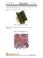
microSD Connector
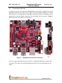
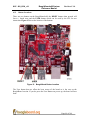
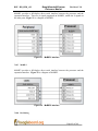
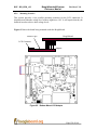
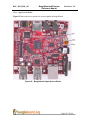
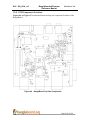
A single microSD connector is provided as a means for the main non-volatile memory
storage on the board. This replaces the 6 in 2 SD/MMC connector found on the
BeagleBoard.
4.13
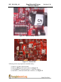
Reset Button
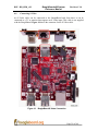
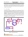
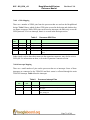
When pressed and released, causes a power on reset of the BeagleBoard.
4.14
User Button
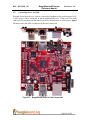
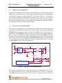
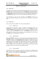
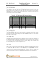
A button is provided on the BeagleBoard to be used as an application button that can be
used by SW as needed. As there is no NAND boot option on the board, this button is no
longer needed to force an SD card boot. It is can be used by the UBoot SW to switch
between user scripts to allow different boot configurations to be selected as long as that
feature is included in the UBoot used. If you press this button on power up, the board will
not boot properly.
4.15
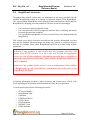
Indicators
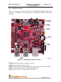
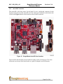
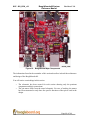
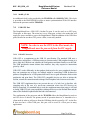
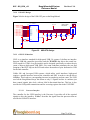
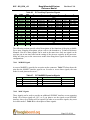
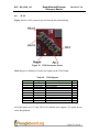
There are five green LEDs on the BeagleBoard that can be controlled by the user.
o One on the TPS65950 that is programmed via the I2C interface
o Two on the processor controlled via GPIO pins
o One Power LED that indicates that power is applied and can be turned off
via SW.
o One to indicate that power is applied to the onboard USB HUB and can be
controlled via the SW.
There is also one red LED on the BeagleBoard that provides an indication that the power
connected to the board exceeds the voltage range of the board. If this LED ever turns on,
please remove the power connector and look for the correct power supply in order to
prevent damage to the board.
4.16
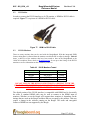
Power Connector
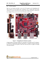
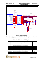
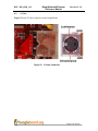
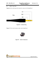
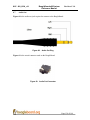
Power can be supplied via the USB OTG connector for some application that does not
require the USB Host ports. A wall supply 5V can be plugged into the DC power jack fro
full access to all functions of the board. When the wall supply is plugged in, it will
remove the power path from the USB connector and will be the power source for the
whole board. The power supply is not provided with the BeagleBoard.
Page 26 of 164