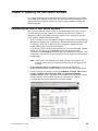
1
ERserver Nortel Networks Layer 2-7 GbE Switch Module for IBM Eserver BladeCenter Hardware Maintenance Manual and Troubleshooting Guide ERserver Nortel Networks Layer 2-7 GbE Switch Module for IBM Eserver BladeCenter Hardware Maintenance Manual and Troubleshooting Guide Note Before using this information and the product it supports, read Appendix C, “Notices”, on page 81. Second Edition (September 2003) Note: The most recent version of this document is available at http://www.ibm.com/pc/support. © Copyright International Business Machines Corporation 2003. All rights reserved. US Government Users Restricted Rights – Use, duplication or disclosure restricted by GSA ADP Schedule Contract with IBM Corp. About this manual This manual contains diagnostic information, a Symptom-to-FRU index, service information, error codes, error messages, and configuration information for the Nortel Networks Layer 2-7 GbE Switch Module for IBM® Eserver BladeCenter™. Note: Throughout this book, the Nortel Networks Layer 2-7 GbE Switch Module for IBM Eserver BladeCenter is referred to as the GbE switch module. Important safety information Be sure to read all caution and danger statements in this book before performing any of the instructions. See “Safety information” on page 47 Leia todas as instruções de cuidado e perigo antes de executar qualquer operação. Prenez connaissance de toutes les consignes de type Attention et Danger avant de procéder aux opérations décrites par les instructions. Lesen Sie alle Sicherheitshinweise, bevor Sie eine Anweisung ausführen. Accertarsi di leggere tutti gli avvisi di attenzione e di pericolo prima di effettuare qualsiasi operazione. Lea atentamente todas las declaraciones de precaución y peligro ante de llevar a cabo cualquier operación. WARNING: Handling the cord on this product or cords associated with accessories sold with this product, will expose you to lead, a chemical known to the State of California to cause cancer, and birth defects or other reproductive harm. Wash hands after handling. ADVERTENCIA: El contacto con el cable de este producto o con cables de accesorios que se venden junto con este producto, pueden exponerle al plomo, un elemento químico que en el estado de California de los Estados Unidos está considerado como un causante de cancer y de defectos congénitos, además de otros riesgos reproductivos. Lávese las manos después de usar el producto. Online support You can download the most current diagnostic, flash, and device driver files from http://www.ibm.com/pc/support on the World Wide Web. Support telephone numbers View support telephone numbers at http://www.ibm.com/planetwide/ on the World Wide Web. © Copyright IBM Corp. 2003 iii iv Nortel Networks Layer 2-7 GbE Switch Module for IBM Eserver BladeCenter: Hardware Maintenance Manual and Troubleshooting Guide Contents About this manual . . . Important safety information Online support . . . . . Support telephone numbers . . . . . . . . . . . . . . . . . . . . . . . . Chapter 1. Introduction . . . . . . . . Specifications and features . . . . . . . Standards . . . . . . . . . . . . . Related publications . . . . . . . . . Notices and statements used in this book . Major components of the GbE switch module Chapter 2. Installing and removing a Installation guidelines . . . . . . System reliability considerations . Handling static-sensitive devices . Installing a switch module . . . . . Removing a switch module . . . . . . . . . . . . . . . . . . . . . . . . . . . . . . . . . . . . . . . . . . . . . . . . . . . . . . . . . . . . iii iii iii iii . . . . . . . . . . . . . . . . . . . . . . . . . . . . . . . . . . . . . . . . . . . . . . . . . . . . . . . . . . . . . . . . . . . . . . . . . . . . . . . . . . . . 1 1 4 4 6 7 switch . . . . . . . . . . . . . . . module . . . . . . . . . . . . . . . . . . . . . . . . . . . . . . . . . . . . . . . . . . . . . . . . . . . . . . . . . . . . . . . . . . . . . . . . . . . 9 10 10 11 12 15 Chapter 3. Information panel LEDs and external ports . . . . . . . . . 17 Information panel . . . . . . . . . . . . . . . . . . . . . . . . 17 LEDs . . . . . . . . . . . . . . . . . . . . . . . . . . . . 17 Chapter 4. Configuring the GbE switch module . . . . . . . . . . . . Establishing a TCP/IP session for the GbE switch through the management module . . . . . . . . . . . . . . . . . . . . . . . . . . . Enabling the external ports . . . . . . . . . . . . . . . . . . . . Establishing a TCP/IP session for the switch through the external switch-module connectors . . . . . . . . . . . . . . . . . . . . . . . . . Externally managing the GbE switch module . . . . . . . . . . . . . Configuring through the Telnet interface . . . . . . . . . . . . . . . . Connecting to the GbE switch module . . . . . . . . . . . . . . . Telnet usage conventions . . . . . . . . . . . . . . . . . . . Accessing the main menu . . . . . . . . . . . . . . . . . . . Logging on to the GbE switch module . . . . . . . . . . . . . . . First-time connection to the GbE switch module . . . . . . . . . . . . Configuring through the browser-based interface . . . . . . . . . . . . Chapter 5. Updating the GbE switch software Determining the level of GbE switch software. . Obtaining the latest level of switch software . . Upgrading the switch software . . . . . . . Resetting and restarting the GbE switch module . . . . . . . . . . . . . . . . . . . . . . . . . . . . . . . . . . . . . . . . . . . . . . . . . . . . . . . . . . . . 19 21 22 24 25 27 27 28 28 28 29 29 33 33 34 34 36 Chapter 6. Diagnostic information . . . . . . . . . . . . . . . . . 39 Running POST . . . . . . . . . . . . . . . . . . . . . . . . . 39 POST errors . . . . . . . . . . . . . . . . . . . . . . . . . . 40 Chapter 7. Parts listing . . . . . . . . . . . . . . . . . . . . . 43 Nortel Networks Layer 2-7 GbE Switch Module for IBM Eserver BladeCenter 43 Appendix A. Getting help and technical assistance . . . . . . . . . . 45 Before you call . . . . . . . . . . . . . . . . . . . . . . . . . 45 © Copyright IBM Corp. 2003 v Using the documentation . . . Getting help and information from Software service and support . Hardware service and support . . . . . the World . . . . . . . . Appendix B. Related service information Safety information . . . . . . . . . . General safety . . . . . . . . . . Electrical safety. . . . . . . . . . Safety inspection guide . . . . . . . Handling electrostatic discharge-sensitive Grounding requirements . . . . . . Safety notices (multi-lingual translations) . . Wide . . . . . . Web . . . . . . . . . . . . . . . . . . . devices . . . . . . . . . . . . . . . . . . . . . . . . . . . . . . . . . . . . . . . . . . . . . . . . . . . . . . 45 45 46 46 . . . . . . . . . . . . . . . . . . . . . . . . . . . . . . . . . . . . . . . . . . . . . . . . . . . . . . . . . . . . . . . . . . . . . . . . . . . . . . . . 47 47 47 48 49 50 50 50 . . . . . . . . . . . . . . . . . . . . . . . . . . . . . . . . . . . . . . . . . . . . . . . . . . . . . . . . statement . . . . . . . . . . . . . . . . . . . . . . . . . . . . . . . . . . . . . . . . . . . . . . . . . . . . 81 82 82 82 83 83 84 84 84 84 84 85 85 85 85 85 Appendix C. Notices . . . . . . . . . . . . . . . Edition notice . . . . . . . . . . . . . . . . . . Trademarks . . . . . . . . . . . . . . . . . . . Important notes. . . . . . . . . . . . . . . . . . Product recycling and disposal . . . . . . . . . . . . Battery return program . . . . . . . . . . . . . . . Electronic emission notices . . . . . . . . . . . . . Federal Communications Commission (FCC) statement . . Industry Canada Class A emission compliance statement . Australia and New Zealand Class A statement . . . . . United Kingdom telecommunications safety requirement. . European Union EMC Directive conformance statement . . Taiwanese Class A warning statement . . . . . . . . Chinese Class A warning statement . . . . . . . . . Japanese Voluntary Control Council for Interference (VCCI) Power cords . . . . . . . . . . . . . . . . . . . Index . . . . . . . . . . . . . . . . . . . . . . . . . . . . 89 vi Nortel Networks Layer 2-7 GbE Switch Module for IBM Eserver BladeCenter: Hardware Maintenance Manual and Troubleshooting Guide Chapter 1. Introduction The GbE switch module is one of up to two GbE switch modules that can be installed in the IBM Eserver BladeCenter Type 8677, also known as the BladeCenter unit. You can obtain up-to-date information about your BladeCenter GbE switch module and other IBM server products at http://www.ibm.com/eserver/xseries/. The product name and serial number are located on the identification label on the side of the GbE switch module. You will need this information when you register your GbE switch module with IBM. The media access control (MAC) address is located on a separate label on the information panel under the external Ethernet port connectors. See the following illustration for the locations of the identification label and the MAC address label. Note: The illustrations in this document might differ slightly from your hardware. GbE switch module Serial number/ identification label Media access control (MAC) address label Specifications and features This section provides a summary of the specifications and features for your Nortel Networks Layer 2-7 GbE Switch Module for IBM Eserver BladeCenter. For detailed information about the features, see the Alteon OS 20.0 Application Guide on the IBM BladeCenter Documentation CD. The Nortel Networks Layer 2-7 GbE Switch Module for IBM Eserver BladeCenter has the following features: v Ports – Four external 1000BASE-T connectors for making 10/100/1000 Mbps connections to a backbone, end stations, and servers – Fourteen internal full-duplex gigabit ports, one connected to each of the blade servers in the BladeCenter unit – Two internal full-duplex 10/100 Mbps ports connected to the management module v Performance features – 64 real servers and 256 real services. © Copyright IBM Corp. 2003 1 – – – – – 64 virtual servers and 256 virtual services. 128 Internet protocol (IP) interfaces. 128 static route entries. 1024 total policy filters. 2048 dynamic route entries. – – – – – 2048 forwarding database (FDB) entries. 4096 address resolution protocol (ARP) entries. Layer 2 through Layer 7 (L2-L7) support. 300,000 simultaneous Layer 2 through Layer 7 (L2-L7) sessions. 802.1D spanning tree support; can be disabled on the entire switch or on a per-port basis. Support for 16 multiple spanning tree groups. 802.1Q tagged virtual local area network (VLAN) support. Support for 128 VLANs. Denial-of-Service protection. – – – – – Forwarding table age time: maximum 1 to 65535 seconds. The default is 300 seconds. – Content-based load balancing - Hypertext transfer protocol (HTTP). - Real time streaming protocol (RTSP). - Domain name system (DNS). – Layer 4 load balancing. – HTTP cookie and secure sockets layer (SSL) session ID persistency. – Link aggregation with 802.3 support on four external ports for up to two static trunk groups. – Media access control (MAC) address learning: Automatic update. Supports 2048 MAC addresses. – Packet forwarding rate: - Full-wire speed for all connections. 148800 packets per second (pps) per port (for 100 Mbps). - 1488100 pps per port (for 1000 Mbps). – Random-access memory (RAM) buffer: 128 MB. – Real server health checking. – Routing Information Protocol version 1 (RIPv1), Border Gateway Protocol version 4 (BGPv4), and Open Shortest Path First version 2 (OSPFv2). – Transmission method: Store-and-forward. v Management – Spanning Tree Protocol (STP) for creation of alternative backup paths and prevention of network loops. – Simple Network Management Protocol (SNMP) version 1. – Fully configurable either in-band or out-of-band control through SNMP-based software. – Flash memory for software upgrades. This can be done through Trivial File Transfer Protocol (TFTP) or Hypertext Transfer Protocol (HTTP) Web interface. – Built-in SNMP management: - Bridge management information base (MIB) (RFC 1493) 2 Nortel Networks Layer 2-7 GbE Switch Module for IBM Eserver BladeCenter: Hardware Maintenance Manual and Troubleshooting Guide - MIB-II (RFC 1213) - 802.1P/Q MIB (RFC 2674) - Interface MIB (RFC 2233) – Browser-based management support – TFTP support – – – – Bootstrap protocol (BOOTP) support Dynamic Host Configuration Protocol (DHCP) client support Password enabled Telnet remote-control console You can also manage the switch by using a Simple Network Management Protocol (SNMP) version 1 interface, as described in the Alteon OS 20.0 Application Guide on the IBM BladeCenter Documentation CD. The SNMP interface supports the following Internet standards: – RFC 1155, Structure and identification of management information for TCP/IP-based internets, M. T. Rose, K. McCloghrie. May-01-1990. – RFC 1157, Simple Network Management Protocol (SNMP). J.D. Case, M. Fedor, M. L. Schoffstall, C. Davin. May-01-1990. – RFC 1212, Concise MIB definitions. M. T. Rose, K. McCloghrie. Mar-01-1991. – RFC 1213, Management Information Base for Network Management of TCP/IP-based internets: MIB-II. K. McCloghrie, M. T. Rose. Mar-01-1991. – RFC 1493, Definitions of Managed Objects for Bridges. E. Decker, P. Langille, A. Rijsinghani, K. McCloghrie. July 1993. – RFC 1573, Evolution of the Interfaces Group of MIB-II. K. McCloghrie, F. Kastenholz. January 1994. – RFC 1643, Definitions of Managed Objects for the Ethernet-like Interface Types. F. Kastenholz. July 1994. – RFC 1657, Definitions of Managed Objects for the Fourth Version of the Border Gateway Protocol (BGP-4) using SMIv2. S. Willis, J. Burruss, J. Chu, Ed. July 1994. – RFC 1724, RIP Version 2 MIB Extension. G. Malkin, F. Baker. November 1994. – RFC 1757, Remote Network Monitoring Management Information Base. S. Waldbusser. February 1995. – RFC 1850, OSPF Version 2 Management Information Base. F. Baker, R. Coltun. November 1995. – RFC 2021, Remote Network Monitoring Management Information Base Version 2 using SMIv2. S. Waldbusser. January 1997 (partial support). – RFC 2037, Entity MIB using SMIv2. K. McCloghrie, A. Bierman. October 1996 (partial support). v Network cables: – 10BASE-T: - UTP Category 3, 4, 5 (100 meters maximum) - 100-ohm STP (100 meters maximum) – 100BASE-TX: - UTP Category 5 (100 meters maximum) - EIA/TIA-568 100-ohm STP (100 meters maximum) – 1000BASE-T: Chapter 1. Introduction 3 - UTP Category 6 (standard for 1 GB devices) UTP Category 5e (100 meters maximum) UTP Category 5 (100 meters maximum) EIA/TIA-568B 100-ohm STP (100 meters maximum) Standards The GbE switch module supports the following standards: v IEEE standards – IEEE 802.1d Spanning Tree Protocol – IEEE 802.1P Tagged Packets – IEEE 802.1Q Tagged VLAN (frame tagging on all ports when VLANs are enabled) – IEEE 802.2 Logical Link Control – IEEE 802.3 10BASE-T Ethernet – IEEE 802.3u 100BASE-TX Fast Ethernet – IEEE 802.3x Full-duplex Flow Control – IEEE 802.3z - 1000BASE-SX Gigabit Ethernet - Link Negotiation Related publications This Hardware Maintenance Manual and Troubleshooting Guide is provided in PDF on the WEB at http://www.ibm.com/pc/support. It contains information to help you solve problems yourself or to provide helpful information to a service technician. In addition to this Hardware Maintenance Manual and Troubleshooting Guide, the following related documentation comes with your GbE switch module: v Rack Installation Instructions This printed publication contains the instructions to install your BladeCenter unit in a rack. v Safety Information This publication is in Portable Document Format (PDF) on the IBM BladeCenter Documentation CD. It contains translated caution and danger statements. Each caution and danger statement that appears in the documentation has a number that you can use to locate the corresponding statement in your language in the Safety Information book. v Eserver BladeCenter Type 8677 Installation and User’s Guide This publication is in PDF on the IBM BladeCenter Documentation CD. It contains general information about your BladeCenter unit, including: – Information about features – How to set up, cable, and start your BladeCenter unit – How to install options in your BladeCenter unit – How to configure your BladeCenter unit – How to perform basic troubleshooting of your BladeCenter unit – How to get help v BladeCenter Management Module User’s Guide 4 Nortel Networks Layer 2-7 GbE Switch Module for IBM Eserver BladeCenter: Hardware Maintenance Manual and Troubleshooting Guide This publication is in PDF on the IBM BladeCenter Documentation CD. It provides general information about the management module, including: – Information about features – How to start the management module – How to install the management module – How to configure and use the management module – How to get help v BladeCenter Management Module Installation Guide This publication is in PDF on the IBM BladeCenter Documentation CD. It provides general information about the management module, including: – How to set up and start the management module – How to install the management module – How to configure the management module – How to get help v BladeCenter HS20 Installation and User’s Guide for each blade server type These publications are in PDF on the IBM BladeCenter Documentation CD. Each provides general information about a blade server, including: – Information about features – How to set up and start your blade server – How to install options in your blade server – How to configure your blade server – How to install an operating system on your blade server – How to perform basic troubleshooting of your blade server – How to get help v Alteon OS 20.0 Application Guide Layer 2-7 GbE Switch Module for IBM Eserver BladeCenter This Nortel Networks publication is in PDF on the IBM BladeCenter Documentation CD. This publication contains detailed setup and installation instructions for the GbE switch module. It provides: – Configuration instructions for your GbE switch module – Information about features – Information about getting help – Guidance for planning, implementing, and administering LAN operating system (LAN OS) software – Usage examples – Troubleshooting information for your GbE switch module v Alteon OS 20.0 Browser-Based Interface Quick Guide Layer 2-7 GbE Switch Module for IBM Eserver BladeCenter This Nortel Networks publication is in PDF on the IBM BladeCenter Documentation CD. It contains information about the browser-based interface that you can use to: – Access switch information – Calculate and obtain statistical data – Perform switch configuration v Alteon OS 20.0 Command Reference Layer 2-7 GbE Switch Module for IBM Eserver BladeCenter Chapter 1. Introduction 5 This Nortel Networks publication is in PDF on the IBM BladeCenter Documentation CD. It includes: – Information about getting started – Information about first-time connection to the GbE switch module – Telnet program interface requirements – Browser-based network interface requirements – Command Line Interface (CLI) operations – Maintenance menus – – – – Statistics Supported SNMP MIBs Syslog messages Usage examples Depending on your blade server model, additional publications might be included on the IBM BladeCenter Documentation CD. In addition to reviewing the publications in this library, be sure to review the following publication for information to help you prepare for system installation and configuration: IBM BladeCenter Planning and Installation Guide at http://www.ibm.com/pc/eserver/bladecenter Note: If you install more then two GbE switch module, you must install an 1800 watt power supply. If you plan to install a GbE switch module in I/O-module bay 3 or 4 of your BladeCenter unit, you must also install an I/O expansion card (also known as an Ethernet expansion card) in the applicable blade server to support the GbE switch modules in these bays. For information about the types of compatible I/O expansion cards for the blade servers, contact your IBM authorized reseller. For details about I/O expansion cards, see Chapter 2, “Installing and removing a switch module”, on page 9 and the IBM Eserver BladeCenter Gigabit Ethernet Expansion Card Installation Guide on the IBM BladeCenter Documentation CD. Notices and statements used in this book The caution and danger statements that appear in this book are also in the multilingual Safety Information book, which is on the IBM BladeCenter Documentation CD. Each statement is numbered for reference to the corresponding statement in the Safety Information book. The following types of notices and statements are used in this book: v Note: These notices provide important tips, guidance, or advice. v Important: These notices provide information or advice that might help you avoid inconvenient or problem situations. v Attention: These notices indicate possible damage to programs, devices, or data. An attention notice is placed just before the instruction or situation in which damage could occur. v Caution: These statements indicate situations that can be potentially hazardous to you. A caution statement is placed just before the description of a potentially hazardous procedure step or situation. 6 Nortel Networks Layer 2-7 GbE Switch Module for IBM Eserver BladeCenter: Hardware Maintenance Manual and Troubleshooting Guide v Danger: These statements indicate situations that can be potentially lethal or extremely hazardous to you. A danger statement is placed just before the description of a potentially lethal or extremely hazardous procedure step or situation. Major components of the GbE switch module The orange color on the release latch on your GbE switch module identifies this device as a hot-swap component. You can install or remove this component while the BladeCenter unit is running. The following illustration shows the major components of your GbE switch module. Note: The illustrations in this document might differ slightly from your hardware. Release latch Information panel Serial number/ identification label Ethernet ports (4) Media access control (MAC) address label For more information about the components of the information panel, see Chapter 3, “Information panel LEDs and external ports”, on page 17 For more information about the MAC address, see the Alteon OS 20.0 Application Guide on the IBM BladeCenter Documentation CD. Chapter 1. Introduction 7 8 Nortel Networks Layer 2-7 GbE Switch Module for IBM Eserver BladeCenter: Hardware Maintenance Manual and Troubleshooting Guide Chapter 2. Installing and removing a switch module The following illustration shows the I/O-module bay locations in the BladeCenter unit. I/O module bay 3 I/O module bay 1 AC DC AC DC I/O module bay 2 I/O module bay 4 Attention: To maintain proper system cooling, each I/O-module bay must contain either a module or a filler module; each blade bay must contain either a blade or a filler blade. Your BladeCenter unit supports a minimum of one hot-plug GbE switch module, in I/O-module bay 1. The GbE switch modules in I/O-module bays 1 and 2 are for the integrated Ethernet controllers in the applicable blade server. The GbE switch modules in I/O-module bays 3 and 4 are for the Ethernet controllers on the I/O expansion card on any applicable blade server. For additional information about the location of the switch module, see the BladeCenter Type 8677 Installation and User’s Guide on the IBM BladeCenter Documentation CD. For details about network interface requirements and expansion options, see the following books: v IBM BladeCenter Planning and Installation Guide at http://www.ibm.com/pc/eserver/bladecenter v Eserver BladeCenter Type 8677 Installation and User’s Guide on the IBM BladeCenter Documentation CD v BladeCenter HS20 Installation and User’s Guide for each blade server type on the IBM BladeCenter Documentation CD © Copyright IBM Corp. 2003 9 Installation guidelines Before you begin to install the GbE switch module in your BladeCenter unit, read the following information: v Read the safety information beginning on page 47 and the guidelines in “Handling static-sensitive devices” on page 11, and read the safety statements in the BladeCenter unit option publications. v The orange color on the release latch on your GbE switch module identifies this device as a hot-swap component. You can install or remove this component while the BladeCenter unit is on. See the instructions in this chapter for more information about installing or removing hot-swap or hot-plug components. v You do not need to turn off the BladeCenter unit to install or replace any of the hot-swap modules on the rear of the BladeCenter unit. v If you plan to install a GbE switch module in I/O-module bay 3 or 4 of your BladeCenter unit, you must also install an I/O expansion card in the applicable blade server to support the GbE switch modules in these bays. System reliability considerations To help ensure proper cooling and system reliability, make sure that: v Each of the I/O-module bays on the rear of the BladeCenter unit has either a module or filler module installed. v A removed hot-swap module is replaced with another module or filler module within 1 minute of removal. v A removed hot-swap blade is replaced with another blade or filler blade within 1 minute of removal. v Cables for the optional modules are routed according to the illustrations and instructions in this book. 10 Nortel Networks Layer 2-7 GbE Switch Module for IBM Eserver BladeCenter: Hardware Maintenance Manual and Troubleshooting Guide Handling static-sensitive devices Attention: Static electricity can damage electronic devices and your system. To avoid damage, keep static-sensitive devices in their static-protective packages until you are ready to install them. To reduce the possibility of electrostatic discharge, observe the following precautions: v Limit your movement. Movement can cause static electricity to build up around you. v Handle the device carefully, holding it by its edges or its frame. v Do not touch solder joints, pins, or exposed printed circuitry. v Do not leave the device where others can handle and damage it. v While the device is still in its static-protective package, touch it to any unpainted metal surface of the BladeCenter chassis or any unpainted metal surface on any other grounded rack component for at least 2 seconds. (This drains static electricity from the package and from your body.) v Remove the device from its package and install it directly into your BladeCenter unit without setting it down. If it is necessary to set down the device, put it back into its static-protective package. Do not place the device on your BladeCenter chassis or on a metal surface. v Take additional care when handling devices during cold weather. Heating reduces indoor humidity and increases static electricity. Chapter 2. Installing and removing a switch module 11 Installing a switch module Statement 8: CAUTION: Never remove the cover on a power supply or any part that has the following label attached. Hazardous voltage, current, and energy levels are present inside any component that has this label attached. There are no serviceable parts inside these components. If you suspect a problem with one of these parts, contact a service technician. 12 Nortel Networks Layer 2-7 GbE Switch Module for IBM Eserver BladeCenter: Hardware Maintenance Manual and Troubleshooting Guide The following illustration shows how to install a switch module in the rear of the BladeCenter unit. Switch module Release latch Complete the following steps to install a switch module: 1. Read the safety information beginning on page 47 and “Installation guidelines” on page 10. Chapter 2. Installing and removing a switch module 13 2. Remove the acoustic attenuation module, if one is installed, from the rear of the BladeCenter unit. Acoustic module Locking handle 3. Select an I/O-module bay in which to install the GbE switch module. Note: For details about I/O-module bay requirements, see the BladeCenter books that are listed on page 9. 4. Remove the filler module from the selected bay. Store the filler module for future use. 5. If you have not already done so, touch the static-protective package that contains the switch module to any unpainted metal surface of the BladeCenter chassis or any unpainted metal surface on any other grounded rack component for at least 2 seconds. 6. Remove the switch module from its static-protective package. 7. Ensure that the release latch on the switch module is in the open position (perpendicular to the module). 8. Slide the switch module into the applicable I/O-module bay until it stops. 9. Push the release latch on the front of the switch module to the closed position. After you insert and lock the switch module, it is turned on, and a power-on self-test (POST) occurs to verify that the switch module is operating correctly. 10. The POST results are displayed by the status LEDs. Make sure that the LEDs on the switch module indicate that it is operating correctly. Make sure that the OK LED on each switch module is lit. See Chapter 3, “Information panel LEDs and external ports”, on page 17 for a more detailed description of the operation of these LEDs. For additional information, see Chapter 6, “Diagnostic information”, on page 39. 11. If you have other switch modules to install, do so now; otherwise, go to step 12. 12. Attach any cables or cords required by the switch module. For the location of the connectors on the BladeCenter unit, see the BladeCenter Type 8677 Installation and User’s Guide on the IBM BladeCenter Documentation CD. For cable requirements, see page 3. 14 Nortel Networks Layer 2-7 GbE Switch Module for IBM Eserver BladeCenter: Hardware Maintenance Manual and Troubleshooting Guide 13. Replace the acoustic attenuation module, if you removed it in step 2 on page 14. Removing a switch module Attention: To maintain proper cooling and system reliability, each I/O-module bay on the rear of the BladeCenter unit must have either a module or filler module installed. If you remove a hot-swap module, you must replace it with another module or filler module within 1 minute of removal. Statement 8: CAUTION: Never remove the cover on a power supply or any part that has the following label attached. Hazardous voltage, current, and energy levels are present inside any component that has this label attached. There are no serviceable parts inside these components. If you suspect a problem with one of these parts, contact a service technician. Chapter 2. Installing and removing a switch module 15 Complete the following steps to remove a switch module: 1. Read the safety information beginning on page 47 and “Installation guidelines” on page 10. 2. Remove the acoustic attenuation module, if one is installed, from the rear of the BladeCenter unit (see step 2 on page 14 for location). 3. Disconnect any cables from the switch module that you are removing. 4. Pull the release latch toward the bottom of the switch module as shown in the following illustration. The module moves out of the bay approximately 0.64 cm (0.25 inch). Switch module Release latch 5. Slide the switch module out of the bay and set it aside. 6. Place either another switch module or a filler module in the bay within 1 minute. 7. If you placed another switch module in the bay, reconnect any cables that you disconnected in step 3. 8. Replace the acoustic attenuation module option, if you removed it in step 2. 16 Nortel Networks Layer 2-7 GbE Switch Module for IBM Eserver BladeCenter: Hardware Maintenance Manual and Troubleshooting Guide Chapter 3. Information panel LEDs and external ports This chapter describes the information panel and LEDs on the GbE switch module. This chapter also identifies the external ports on the information panel. Information panel As shown in the following illustration, the information panel of the GbE switch module contains: v Comprehensive LEDs, which display the status of the GbE switch module and the network (see “LEDs”). v Four external 1000BASE-T Ethernet ports for 10/100/1000 Mbps connections to external Ethernet devices, such as backbones, end stations, and servers. These ports are respectively identified as EXT1, EXT2, EXT3, and EXT4 in the switch configuration menus and are labeled 1 through 4 (from top to bottom) on the GbE switch module. LEDs OK LINK 1 TX/RX LINK 2 Ports TX/RX LEDs LINK 3 TX/RX LINK 4 TX/RX LEDs The LEDs on the information panel of the GbE switch module are OK and GbE switch module error (fault). In addition, each external port on the GbE switch module contains an Ethernet link OK LED and an Ethernet Tx/Rx LED. The following illustration shows the LEDs on the GbE switch module. A description of each LED follows the illustration. © Copyright IBM Corp. 2003 17 LEDs OK LINK 1 TX/RX LINK 2 Ports TX/RX LEDs LINK 3 TX/RX LINK 4 TX/RX Notes: 1. The illustrations in this document might differ slightly from your hardware. 2. An amber LED is lit when a system error or event has occurred. To identify the error or event, check the LEDs on the information panel of the GbE switch module. For additional information, see Chapter 6, “Diagnostic information”, on page 39. OK: This green LED is on the left side of the information panel, above the four external 10/100/1000 Mbps ports. When this LED it lit, it indicates that the GbE switch module has passed the power-on self-test (POST) with no critical faults and is operational. GbE switch module error (fault): This amber LED is on the right side of the information panel, above the four external 10/100/1000 Mbps ports. When this LED it lit, it indicates that the GbE switch module has a fault. If the GbE switch module fails the POST or detects an operational fault, this LED will be lit. Note: When this LED is lit, the system-error LED on the BladeCenter unit will also be lit. Ethernet link OK: This green link status LED is at the top of each external 10/100/1000 Mbps port. When this LED is lit on a port, it indicates that there is a connection (or link) to a device on that connector. Ethernet Tx/Rx: This green activity LED is at the bottom of each external 10/100/1000 Mbps port. When this LED blinks on a port, it indicates that data is being transmitted or received (that is, activity is occurring) between that port and another device on the network link. The blink frequency is proportional to the amount of traffic on the network link. 18 Nortel Networks Layer 2-7 GbE Switch Module for IBM Eserver BladeCenter: Hardware Maintenance Manual and Troubleshooting Guide Chapter 4. Configuring the GbE switch module The GbE switch module supports two remote-access modes for management through Ethernet connections. The GbE switch module has an internal Ethernet path to the management module and the four external Ethernet ports on the GbE switch module. You can select the mode that is best suited for your BladeCenter environment. v The default mode uses the internal path to the management module only. In this mode, the remote-access link to the management console must be attached to the 10/100 Mbps Ethernet connector on the management module. The IP addresses and SNMP parameters of the GbE switch modules can be automatically assigned by the IBM Director BladeCenter Deployment wizard when available or you must manually assign them through the BladeCenter Management Configuration Program. This mode enables the system administrator to provide a secure LAN for management of the BladeCenter subsystems separately from the data network. See “Establishing a TCP/IP session for the GbE switch through the management module” on page 21 for additional information. Important: In this mode, the GbE switch module does not respond to remote-management commands through the four external Ethernet ports on the GbE switch module. See the applicable BladeCenter Installation and User’s Guide on the IBM BladeCenter Documentation CD for additional instructions for configuring the GbE switch module for this mode of operation. v The system administrator can choose to enable remote management of the GbE switch module through the four external ports on the GbE switch module, instead of or in addition to access through the management module. This mode can be enabled only through the management module configuration interface. When this mode is enabled, the external Ethernet ports will support both management traffic and BladeCenter application data traffic. See “Enabling the external ports” on page 22 for additional information. v This mode enables the GbE switch module IP addresses to be on a different IP subnet than the management modules. This is useful when the GbE switch modules are to be managed and controlled as part of the overall network infrastructure, while secure management of other BladeCenter subsystems is maintained through the management module. However, management-module access to the Gigabit switch-module link will be lost if the GbE switch module IP address is not on the same IP subnet as the management module. The Alteon OS 20.0 Application Guide on the IBM BladeCenter Documentation CD contains additional instructions for configuring the GbE switch module for this mode of operation. See “Establishing a TCP/IP session for the switch through the external switch-module connectors” on page 24 for additional information. Important: 1. Before you configure your GbE switch module, be sure that the management modules in your BladeCenter unit are properly configured. See the applicable BladeCenter Installation and User’s Guide publications on the IBM BladeCenter Documentation CD for more information. 2. The default IP address of the GbE switch module is 10.90.90.9x, where x is the switch bay identifier. 3. If you change the IP address of the GbE switch module and restart the BladeCenter unit, the GbE switch module will maintain this new IP address as its default value. © Copyright IBM Corp. 2003 19 4. The management module and the GbE switch module can communicate with each other only if they are on the same IP subnet. 5. When you use the management module Web interface to update the GbE switch module configuration, the management module firmware saves the new configuration in its internal non-volatile random-access memory (NVRAM). If the switch module restarts, the management module applies the saved configuration to the switch module. If, for some reason, the switch module restarts and the management module cannot apply the saved configuration to the switch module, the switch module defaults to using the configuration that it had previously saved. If the subnet IP address of the switch module does not match the subnet IP address of the management module, you might not be able to manage the switch module any more. 6. For switch communication with a remote management station, such as the IBM Director server, through the management module external Ethernet port, the switch module internal network interface and the management module internal and external interfaces must be on the same IP subnet. See the following publications on the IBM BladeCenter Documentation CD for specific details about configuring the GbE switch module: v The applicable BladeCenter Installation and User’s Guide publications v Alteon OS 20.0 Application Guide v Alteon OS 20.0 Browser-Based Interface Quick Guide v Alteon OS 20.0 Command Reference In addition to reviewing the publications in this library, be sure to review the following publications for information to help you prepare for system installation and configuration: v BladeCenter Management Module User’s Guide on the IBM BladeCenter Documentation CD v BladeCenter Management Module Installation Guide on the IBM BladeCenter Documentation CD v IBM BladeCenter Planning and Installation Guide at http://www.ibm.com/pc/eserver/bladecenter You can manage and configure the GbE switch using the management module or an external GbE switch interface. The following figure is used as an example of establishing a TCP/IP session through the management module or through the external interface. When the GbE switch module is set to use the factory default configuration, it can only be accessed through the management module VLAN. “Client A ” manages the GbE switch module through the default management module configuration interface. The management module is always enabled and always a member of VLAN 4095 and interface 128. VLAN 4095 and interface 128 can never be disabled. You can always manage the GbE switch module over this interface, provided that the IP addresses of the client, the management module, and the GbE switch module are on the same subnet, as shown in the following table. 20 Network entity IP address Client A 192.168.70.1 Nortel Networks Layer 2-7 GbE Switch Module for IBM Eserver BladeCenter: Hardware Maintenance Manual and Troubleshooting Guide Network entity IP address Management module 192.168.70.125 GbE switch module 192.168.70.127 Notes: 1. IF 128 defines a subnet to which the GbE, MM eth0, MM eth1 and Client A MUST all belong. Client A on this subnet is used to access the MM BBI by setting the browser to 192.168.70.125. Client A eth0 192.168.70.125 2. IF 1 allows Client B to access the Gbe management user interfaces (e.g. telnet, BBI, SNMP). HTTP 192.168.70.1 MM Client B Default Vlan Vlan 1 15 EXT1 Telnet 17 MGT1 IF 128 => 192.168.70.127 eth1 eth1 192.168.70.126 EXT2 18 10.10.1.2 EXT3 19 EXT4 20 10.10.1.1 <= IF 1 Mgmt VLAN Vlan 4095 GbE Establishing a TCP/IP session for the GbE switch through the management module Complete the following steps to establish a TCP/IP session for the switch through the management module: 1. Access and log on to the management module as described in the BladeCenter Management Module User’s Guide on the IBM BladeCenter Documentation CD. If necessary, obtain the IP address of the management module from your system administrator. The login window opens. If you do not have an assigned user identifier (ID) and initial password, type the default user ID (USERID) in the User ID field and the default password (PASSW0RD) in the Password field (where the sixth alphanumeric character is the number zero, not the letter O) and click OK. The main page in the management module opens. Note: Capital letters are required; these fields are both case-sensitive. To increase system security, change the password after you log on for the first time. 2. Select Management on the I/O Module Tasks menu on the left side of the BladeCenter Management Module window. 3. From the I/O Module Management portion of the window, click the bay number that corresponds to the location of the GbE switch module that you installed. The applicable bay number (in this example, bay 1) appears in the bottom portion of the window, followed by other related switch-module information, including the IP address. The switch-module information is divided under two headings: Current IP Configuration and New Static IP Configuration. Chapter 4. Configuring the GbE switch module 21 4. To change the IP address of the GbE switch module, use the Tab key to reach the IP address data field under the New Static IP Configuration heading; then, type the new IP address and click Save. 5. Click Advanced Management under the applicable bay information (in this example, bay 1) in the BladeCenter Management Module window. You can now start a browser-based interface session, a Telnet session, or a Secure Shell (SSH) session. Note: The default setting for the SSH session is disabled. To enable this setting, you must use the CLI. The browser-based interface and the Telnet program are different ways to access the same internal switching software and configure it. Thus, all the settings that you encounter in browser-based management are the same as those found in the Telnet program. v If your system application requires that you use the browser-based interface program, see “Configuring through the browser-based interface” on page 29 for additional information. v If your system application requires that you use the Telnet program, see “Configuring through the Telnet interface” on page 27 for additional information. v For information about running an SSH session, see the Alteon OS 20.0 Command Reference on the IBM BladeCenter Documentation CD. Enabling the external ports To access and manage your GbE switch module from an external environment, you must enable certain features, such as the external ports (ports) and external management over all ports, through the management module. After you enable these features, you can establish a TCP/IP session for the switch through the external GbE switch module connection as described in “Establishing a TCP/IP session for the switch through the external switch-module connectors” on page 24. Complete the following steps to configure the external Ethernet interface and to enable the external ports: 1. Access and log on to the management module as described in the BladeCenter Management Module User’s Guide on the IBM BladeCenter Documentation CD. If necessary, obtain the IP address of the management module from your system administrator. The login window opens. 22 Nortel Networks Layer 2-7 GbE Switch Module for IBM Eserver BladeCenter: Hardware Maintenance Manual and Troubleshooting Guide Enter your user ID and password. If you do not have an assigned user ID and initial password, type the default user ID (USERID) in the User ID field and the default password (PASSW0RD) in the Password field (where the sixth alphanumeric character is the number zero, not the letter O) and click OK. The main page in the management module opens. Note: Capital letters are required; these fields are both case-sensitive. To increase system security, change the password after you log on for the first time. 2. Select Management on the I/O Module Tasks menu on the left side of the BladeCenter Management Module window. 3. Make sure that the following GbE switch-module features are enabled (I/O Module Tasks → Management → Advanced Management in the management module browser-based user interface): a. External ports b. External management over all ports The default value is Disabled for both features. If these features are not already enabled, change the value to Enabled. Then, click Save. Chapter 4. Configuring the GbE switch module 23 Note: See the applicable BladeCenter Installation and User’s Guide publications on the IBM BladeCenter Documentation CD for additional information about enabling external management over all ports. 4. Click Advanced Management under the applicable bay information in the BladeCenter Management Module window. You can now start a browser-based interface session, a Telnet session, or a Secure Shell (SSH) session. Otherwise, continue with “Establishing a TCP/IP session for the switch through the external switch-module connectors”. Establishing a TCP/IP session for the switch through the external switch-module connectors To establish a TCP/IP session for the switch through the external GbE switch-module connectors, you must provide a connection to the Ethernet network through the GbE switch module. To do this, you must first enable the external interfaces as described in “Enabling the external ports” on page 22, and then set up the TCP/IP address for the GbE switch module. Complete the following steps: 1. Access and log on to the management module as described in the BladeCenter Management Module User’s Guide on the IBM BladeCenter Documentation CD. If necessary, obtain the IP address of the management module from your system administrator. The login window opens. If you do not have an assigned user ID and initial password, type the default user ID (USERID) in the User ID field and the default password (PASSW0RD) in the Password field (where the sixth alphanumeric character is the number zero, not the letter O) and click OK. The main page in the management module opens. Note: Capital letters are required; these fields are both case-sensitive. To increase system security, change the password after you log on for the first time. 24 Nortel Networks Layer 2-7 GbE Switch Module for IBM Eserver BladeCenter: Hardware Maintenance Manual and Troubleshooting Guide 2. Select Management on the I/O Module Tasks menu on the left side of the BladeCenter Management Module window. 3. From the I/O Module Management portion of the window, click the bay number that corresponds to the location of the GbE switch module that you installed. The applicable bay number appears in the bottom portion of the window, followed by other related switch-module information, including the IP address. The switch-module information is divided under two headings: Current IP Configuration and New Static IP Configuration. 4. To change the IP address of the GbE switch module, use the Tab key to reach the IP address data field under the New Static IP Configuration heading; then, type the new IP address and click Save. You can set up the TCP/IP address for the GbE switch module in one of two ways: v Use the default TCP/IP address. v Obtain a valid, unique TCP/IP address from your system administrator. If you obtain a valid, unique TCP/IP address from your system administrator, you can set up the new TCP/IP address for the GbE switch module from the management module, as shown in the following window: Type the new TCP/IP address of the GbE switch module in the IP address data field under the New Static IP Configuration heading; then, click Save. You are now ready to set up the GbE switch. Externally managing the GbE switch module The following procedure describes how to configure the GbE switch module to enable management through the external ports (EXT1 to EXT4). See the following illustration for an example topology for enabling external management of the GbE switch module. In this illustration, “Client B” manages the GbE switch using the Chapter 4. Configuring the GbE switch module 25 external interface Start a Telnet session with the GbE switch module. Click Start Telnet Session, as shown in the following illustration. For additional information, see “Configuring through the Telnet interface” on page 27. After the Telnet session is established, you will use the CLI of the GbE switch module to enter commands. To externally manage the GbE switch module, you will establish a layer 3 IP address and mask to communicate with your management client (“Client B” in the previous illustration). You will also define a layer 2 VLAN and an interface over which the client can communicate with the GbE switch module. You can choose the VLAN and interface for your external management client, or use the default values. There is a maximum of 128 available interfaces for VLANs. You can assign the management IP address to the VLAN ID from 1 to 4094 to any of these interfaces. The following example shows how to create this configuration using the CLI: 26 Nortel Networks Layer 2-7 GbE Switch Module for IBM Eserver BladeCenter: Hardware Maintenance Manual and Troubleshooting Guide /cfg/13/if 1/mask 255.255.255.0 /cfg/13/if 1/addr 10.10.1.1 /cfg/13/if 1/vlan 1 /cfg/13/if 1/ena apply save “Client B” now has access to manage the GbE switch module. See the following publications on the IBM BladeCenter Documentation CD for specific details about configuring the GbE switch module: v Alteon OS 20.0 Application Guide v Alteon OS 20.0 Browser-Based Interface Quick Guide v Alteon OS 20.0 Command Reference For additional information about the management module, see the BladeCenter Management Module User’s Guide on the IBM BladeCenter Documentation CD. For additional information about establishing a remote external Ethernet connection, see the BladeCenter Management Module Installation Guide on the IBM BladeCenter Documentation CD. The browser-based interface and the Telnet program are different ways to access the same internal switching software and configure it. Thus, all the settings that you encounter in browser-based management are the same as those found in the Telnet program. v If your system application requires that you use the browser-based interface program, see “Configuring through the browser-based interface” on page 29 for additional information. v If your system application requires that you use the Telnet program, see “Configuring through the Telnet interface” for additional information. v For information about running an SSH session, see the Alteon OS 20.0 Command Reference on the IBM BladeCenter Documentation CD. Configuring through the Telnet interface Your GbE switch module supports a management interface that you can use to set up and control the GbE switch module over the network using the Telnet protocol. You can use this facility to perform many basic network management functions. In addition, you can use the Telnet interface to configure the GbE switch module for management using an SNMP-based network management system. The following sections describe how to use the Telnet interface to access the GbE switch module, change its settings, and monitor its operation. Connecting to the GbE switch module When you know the IP address for your switch module and provided that you have an existing network connection, you can use the Telnet program (in VT-100 compatible terminal mode) to access and control the GbE switch module. The Telnet program and your switch module must be on the same network. If you need to obtain the IP address for your switch module or establish a network connection, Chapter 4. Configuring the GbE switch module 27 contact your system or network administrator. Be sure to use the correct IP address in the required command, as specified in “Accessing the main menu”. Telnet usage conventions The Telnet interface uses the following conventions: v Items in angle brackets ( < > ) can be toggled among several choices through the spacebar. v Items in square brackets ( [ ] ) can be changed by typing a new value. You can use the Backspace and Delete keys to erase characters behind and in front of the cursor. v The Up Arrow and Down Arrow keys, the Left Arrow and Right Arrow keys, the Tab key, and the Backspace key can be used to move between selected items. v Items in uppercase are commands. Moving the selection to a command and pressing Enter will process that command. Important: The command APPLY makes changes to the switch configuration for the current session only. If you want your changes to be permanent, select Save Changes from the main menu. Selecting Save Changes enters the current switch configuration, including all changes, into NVRAM and then restarts the GbE switch module. Accessing the main menu Complete the following steps to connect to the GbE switch module through the Telnet interface: 1. From a DOS prompt command line, type telnet x and press Enter (where x is the IP address for your switch module). 2. If you do not have an assigned initial password, type the default password (admin) in the Password field and click OK. 3. Press Enter, and you will be given access to the main menu, shown in the following illustration. Note: The first user automatically gets root privileges. Create at least one root-level user for the GbE switch module when you set up your user accounts. See the Alteon OS 20.0 Application Guide on the IBM BladeCenter Documentation CD for complete details. Logging on to the GbE switch module To log in after you have created a registered user, complete the following steps from the login window (see “First-time connection to the GbE switch module” on page 29 for additional information): 28 Nortel Networks Layer 2-7 GbE Switch Module for IBM Eserver BladeCenter: Hardware Maintenance Manual and Troubleshooting Guide 1. Type your user ID and press Enter. 2. Type your password and press Enter. The main menu window opens based on your access level or privilege. After you log on to the GbE switch module, you can perform the tasks that are described in the Alteon OS 20.0 Application Guide and other books on the IBM BladeCenter Documentation CD. First-time connection to the GbE switch module The GbE switch module supports user-based security that enables you to prevent unauthorized users from accessing the GbE switch module or changing its settings. This section describes how to log on to the GbE switch module. The first time that you turn on the GbE switch module, you must set the date and time, either through the browser-based interface or the Telnet interface. Because the GbE switch module does not contain a battery-backed real-time clock, you also must manually reset the date and time whenever any of the following conditions exists: v The GbE switch module is turned off and then back on v The GbE switch module is restarted v The GbE switch module software is updated The following illustration shows how to set the date and time through the Telnet interface. Configuring through the browser-based interface This section describes how to use the browser-based interface to access and configure the internal switching software. This section also describes some of the browser-based GbE switch module management features. For more detailed information about configuring your GbE switch module, see the Alteon OS 20.0 Application Guide and the Alteon OS 20.0 Browser-Based Interface Quick Guide on the IBM BladeCenter Documentation CD. The GbE switch module offers an embedded HTML, browser-based interface that you can use to manage the switch through a standard browser, such as Opera, Netscape Navigator/Communicator, or Microsoft® Internet Explorer. The Web Chapter 4. Configuring the GbE switch module 29 browser acts as an access tool and can communicate directly with the switch using HTTP. Your browser window might vary from the window illustrations in this book. Note: This browser-based interface does not accept Chinese language input (or other double-byte character-set languages). The browser-based interface contains these features: v Since the browser-based interface is a built-in component of the Alteon OS switch software, you do not have to install a separate interface program. v Two levels of password protection. v User-friendly design. v The same configuration and monitoring functions as in the command-line interface (CLI). v Upgradeable upon the availability of future Alteon OS switch software updates. Before you can access and start the browser-based interface, you must have: v Installed the GbE switch module in the BladeCenter unit Verified that the Alteon OS switch software is installed on the GbE switch module Configured at least one IP interface on the switch module A computer or workstation with network access to the switch module A frame-capable Web-browser program, such as Internet Explorer (version 6.0x or later) or Netscape Navigator (version 4.7x or later) v Enabled the frames and the JavaScript™ program in your Web browser v Enabled access to the browser-based interface v v v v To enable access to the browser-based interface, use this command from the CLI: >> Main# /cfg/sys/http <enable (or just e)> See the Alteon OS 20.0 Command Reference on the IBM BladeCenter Documentation CD for details about: v Configuring IP interfaces through the CLI v Accessing and configuring the switch module through the CLI To verify that the latest Alteon OS switch software is installed on the GbE switch module or to update the software, see Chapter 5, “Updating the GbE switch software”, on page 33. To start the browser-based interface, enter the IP address of the switch module in the address field of your browser, in the format http://xxx.xxx.xxx.xxx. The login window opens. If you do not have an assigned user ID and initial password, type the default user ID (admin) in the User Name field and the default password (admin) in the Password field and click OK. Notes: 1. The passwords used to access the GbE switch module are case-sensitive. 2. To increase system security, change the password after you log on for the first time. 30 Nortel Networks Layer 2-7 GbE Switch Module for IBM Eserver BladeCenter: Hardware Maintenance Manual and Troubleshooting Guide A window similar to the one in the following illustration opens. The left-side panel contains the main menu. The top panel shows a real-time information-panel display of the GbE switch module. These items are described in detail in the Alteon OS 20.0 Application Guide on the IBM BladeCenter Documentation CD. Chapter 4. Configuring the GbE switch module 31 32 Nortel Networks Layer 2-7 GbE Switch Module for IBM Eserver BladeCenter: Hardware Maintenance Manual and Troubleshooting Guide Chapter 5. Updating the GbE switch software This chapter describes how to determine the level of the software that is installed on the GbE switch module, how to obtain the latest level of switch software, how to upgrade the switch software, and how to reset the switch module to activate the software upgrade. Determining the level of GbE switch software After you install the GbE switch module in your BladeCenter unit, make sure that the latest Alteon OS switch software is installed on the GbE switch module. To determine the level of the Alteon OS switch software that is installed on the GbE switch module, complete the following steps: 1. Access and log on to the management module as described in the BladeCenter Management Module User’s Guide on the IBM BladeCenter Documentation CD. If necessary, obtain the IP address of the management module from your system administrator. The login window opens. If you do not have an assigned user identifier (ID) and initial password, type the default user ID (USERID) in the User ID field and the default password (PASSW0RD) in the Password field (where the sixth alphanumeric character is the number zero, not the letter O) and click OK. The main page in the management module opens. Note: Capital letters are required; these fields are both case-sensitive. To increase system security, change the password after you log on for the first time. 2. Select Firmware VPD on the Monitors menu on the left side of the BladeCenter Management Module window. The Firmware VPD window opens. 3. On the Firmware VPD window, locate the I/O Module Firmware VPD heading between the Blade Server Firmware VPD and Management Module Firmware VPD headings. Page down to the number of the I/O module bay that contains the GbE switch module that you just installed; then, note the corresponding level of the software for the switch module. © Copyright IBM Corp. 2003 33 Obtaining the latest level of switch software To determine the latest level of the Alteon OS switch software that is available from IBM, complete the following steps: 1. Go to http://www.ibm.com/pc/support/; then, click Support & downloads. 2. Type the switch model number. A window opens, displaying the latest level of available software. 3. Compare the level of software that you noted in the I/O Module Firmware VPD section of the Firmware VPD window to the latest level of available software. If the two software levels do not match, download the latest level from the World Wide Web to your switch module. The GbE switch module contains two software operating-system images. Therefore, you can always return to a previous image if the current download process fails. Upgrading the switch software The switch software is upgraded through a TFTP server application. Typically, this software runs as an application under your operating system. Make sure that this software is installed on your server; then, download the software images from the IBM Web site into a directory on your TFTP server. Enable the TFTP server and set its default directory to the one where the image is. To transfer the software image files from the TFTP server to the switch, you must establish a Telnet session through the management module. The Telnet session will work correctly only if all three network entities (TFTP server, management module, and switch IP addresses) are on the same subnet. Use the management module graphical user interface (GUI) to configure the IP addresses of the management module external interface (eth0) and the GbE switch module so that they both are on the same subnet as the TFTP server. 34 Nortel Networks Layer 2-7 GbE Switch Module for IBM Eserver BladeCenter: Hardware Maintenance Manual and Troubleshooting Guide In this illustration, the IP addresses and masks in the following table are used. Network entity IP address Mask TFTP server 192.168.2.178 255.255.255.0 Management module (eth0) 192.168.2.237 255.255.255.0 GbE switch current IP configuration 192.168.2.51 255.255.255.0 Note: With this configuration, you can ping the GbE switch module. Use the management module GUI to start a Telnet session, as described in the following steps. The requirements for running a Telnet session are described in Chapter 4, “Configuring the GbE switch module”, on page 19. 1. Access and log on to the management module as described in the BladeCenter Management Module User’s Guide on the IBM BladeCenter Documentation CD. The login window opens. If you do not have an assigned user identifier (ID) and initial password, type the default user ID (USERID) in the User ID field and the default password (PASSW0RD) in the Password field (where the sixth alphanumeric character is the number zero, not the letter O) and click OK. Type n when asked if you want to run setup. The main page in the management module opens. Note: Capital letters are required; these fields are both case-sensitive. To increase system security, change the password after you log on for the first time. 2. Select Management on the I/O Module Tasks menu on the left side of the BladeCenter Management Module window. The I/O Module Tasks window opens. 3. Start a Telnet session. Click Start Telnet Session, as shown in the following illustration. The following illustration shows the TFTP window for the software download to the GbE switch module. Complete the following steps to upgrade the switch software: Chapter 5. Updating the GbE switch software 35 1. Using the CLI, type the following command and press Enter: /boot/gtimg imageX TADDR zzzzz (where imageX is the image to be installed and zzzzz is the operating-system image software; for example, GbE-1.0.0.20-os.img). 2. Reset and restart the GbE switch module as described in “Resetting and restarting the GbE switch module”. 3. Using the CLI, type the following command and press Enter: /boot/gtimg boot TADDR yyyyy (where yyyyy is the boot image software; for example, GbE-1.0.0.24-boot.img). 4. Reset and restart the GbE switch module as described in “Resetting and restarting the GbE switch module”. Note: There might only be one image to install. Resetting and restarting the GbE switch module To activate the new image or images, you must reset the GbE switch module through the management module GUI. Complete the following steps to reset the GbE switch module: 1. Select Management on the I/O Module Tasks menu on the left side of the BladeCenter Management Module window. The I/O Module Tasks window opens. 2. Select the I/O module bay on which the software update was just installed. 3. 4. 5. 6. 7. From the I/O Module Tasks window, select Power/Restart. Click POWER OFF SWITCH MODULE. Select the I/O module bay on which the software update was just installed. Click POWER ON SWITCH MODULE. Wait 70 seconds for POST to be completed. 8. Make sure that the latest Alteon OS switch software was correctly installed on the GbE switch module. Select Firmware VPD on the Monitors menu on the left side of the BladeCenter Management Module window. The Firmware VPD window opens. 9. On the Firmware VPD window, locate the I/O Module Firmware VPD heading between the Blade Server Firmware VPD and Management Module 36 Nortel Networks Layer 2-7 GbE Switch Module for IBM Eserver BladeCenter: Hardware Maintenance Manual and Troubleshooting Guide Firmware VPD headings. Page down to the number of the I/O module bay that contains the GbE switch module that you just installed; then, note the corresponding level of the software for the switch module. 10. Make sure that the latest Alteon OS switch software was correctly installed on the GbE switch module. Chapter 5. Updating the GbE switch software 37 38 Nortel Networks Layer 2-7 GbE Switch Module for IBM Eserver BladeCenter: Hardware Maintenance Manual and Troubleshooting Guide Chapter 6. Diagnostic information If you are having a problem, use the following information and the to help you determine the cause of the problem and the action to take. The Alteon OS 20.0 Application Guide on the IBM BladeCenter Documentation CD contain more information about troubleshooting the GbE switch module. Running POST To ensure that it is fully operational, the GbE switch module processes a series of tests during power-up or a restart (power-on self-test or POST). These tests take approximately 1 minute to complete. The management module reads the test results and displays them for you. During normal operation, these tests are completed without error, and the green OK LED is lit. However, if POST fails, the amber GbE switch module error (fault) LED and the system-error LED on the BladeCenter unit will be lit. An event is stored in the event log in the System Status panel of the management module. The specific failure is displayed on the System Status I/O Module panel of the management module. The following illustrations are examples of the windows that will be displayed if a POST error occurs. Note: For the location and description of the GbE switch module LEDs, see Chapter 3, “Information panel LEDs and external ports”, on page 17. © Copyright IBM Corp. 2003 39 POST errors There are two types of errors: noncritical and critical. Noncritical errors apply to one port, and the GbE switch module is operational. You can continue to operate the GbE switch module; however, you must replace it as soon as possible. When critical errors occur, the GbE switch module does not operate. If a critical error occurs, complete the following steps: 1. Open the Management Module Switch Information window. 2. Turn off the GbE switch module; then, turn it back on. 3. After POST is completed, the management module displays the results. Refresh the window to view the POST results. If the error remains, the GbE switch module is defective. Replace the GbE switch module. The following table describes the basic critical and noncritical failures. This abbreviated list is representative; it is not intended as an exhaustive list. An error code is associated with each failure. Error codes appear on the Management Module Switch Information window. Be sure to note the applicable error code and corresponding failure. You might need to provide this information when you call the IBM HelpCenter®. For more details, see Appendix A, “Getting help and technical assistance”, on page 45. Note: Before replacing a GbE switch module, restart the module and run the extended diagnostic program through the management module interface. Table 1. POST error codes 40 POST error code (in Failing functional hex) area Failure criticality FRU/action 00 to 7F Basic internal functions. Critical Replace the GbE switch module. 80 to 9F Internal interface errors. Noncritical Replace the GbE switch module. A0 to AF External interface errors. Noncritical Replace the GbE switch module. Nortel Networks Layer 2-7 GbE Switch Module for IBM Eserver BladeCenter: Hardware Maintenance Manual and Troubleshooting Guide Table 1. POST error codes (continued) POST error code (in Failing functional hex) area Failure criticality FRU/action B0 to FE Reserved Noncritical Replace the switch module. FF No error found, the switch is good. Operational N/A Chapter 6. Diagnostic information 41 42 Nortel Networks Layer 2-7 GbE Switch Module for IBM Eserver BladeCenter: Hardware Maintenance Manual and Troubleshooting Guide Chapter 7. Parts listing This parts listing supports the Nortel Networks Layer 2-7 GbE Switch Module for IBM Eserver BladeCenter. Note: Field replaceable units (FRUs) should be serviced only by qualified field service technicians. Customer replaceable units can be replaced by the customer. Nortel Networks Layer 2-7 GbE Switch Module for IBM Eserver BladeCenter GbE switch module Serial number/ identification label Option GbE switch module assembly © Copyright IBM Corp. 2003 Media access control (MAC) address label FRU No. 73P9044 CRU/FRU CRU 43 44 Nortel Networks Layer 2-7 GbE Switch Module for IBM Eserver BladeCenter: Hardware Maintenance Manual and Troubleshooting Guide Appendix A. Getting help and technical assistance If you need help, service, or technical assistance or just want more information about IBM products, you will find a wide variety of sources available from IBM to assist you. This appendix contains information about where to go for additional information about IBM and IBM products, what to do if you experience a problem with your BladeCenter unit, and whom to call for service, if it is necessary. Before you call Before you call, make sure that you have taken these steps to try to solve the problem yourself: v Check all cables to make sure that they are connected. v Check the power switches to make sure that the system is turned on. v Use the troubleshooting information in your system documentation, and use the diagnostic tools that come with your system. v Go to the IBM Support Web site at http://www.ibm.com/pc/support to check for technical information, hints, tips, and new device drivers. v Use an IBM discussion forum on the IBM Web site to ask questions. You can solve many problems without outside assistance by following the troubleshooting procedures that IBM provides in the online help or in the publications that are provided with your system and software. The information that comes with your system also describes the diagnostic tests that you can perform. Most xSeries and IntelliStation® systems, operating systems, and programs come with information that contains troubleshooting procedures and explanations of error messages and error codes. If you suspect a software problem, see the information for the operating system or program. Using the documentation Information about your IBM xSeries or IntelliStation system and preinstalled software, if any, is available in the documentation that comes with your system. That documentation includes printed books, online books, README files, and help files. See the troubleshooting information in your system documentation for instructions for using the diagnostic programs. The troubleshooting information or the diagnostic programs might tell you that you need additional or updated device drivers or other software. IBM maintains pages on the World Wide Web where you can get the latest technical information and download device drivers and updates. To access these pages, go to http://www.ibm.com/pc/support and follow the instructions. Also, you can order publications through the IBM Publications Ordering System at http://www.elink.ibmlink.ibm.com/public/applications/publications/cgibin/pbi.cgi. Getting help and information from the World Wide Web On the World Wide Web, the IBM Web site has up-to-date information about IBM xSeries and IntelliStation products, services, and support. The address for IBM xSeries information is http://www.ibm.com/eserver/xseries/. The address for IBM IntelliStation information is http://www.ibm.com/pc/intellistation/. You can find service information for your IBM products, including supported options, at http://www.ibm.com/pc/support. If you click Profile from the support page, you © Copyright IBM Corp. 2003 45 can create a customized support page. The support page has many sources of information and ways for you to solve problems, including: v Diagnosing problems, using the IBM Online Assistant v Downloading the latest device drivers and updates for your products v Viewing Frequently Asked Questions (FAQ) v Viewing hints and tips to help you solve problems v Participating in IBM discussion forums v Setting up e-mail notification of technical updates about your products Software service and support Through IBM Support Line, you can get telephone assistance, for a fee, with usage, configuration, and software problems with xSeries servers, IntelliStation workstations, and appliances. For information about which products are supported by Support Line in your country or region, go to http://www.ibm.com/services/sl/products/. For more information about Support Line and other IBM services, go to http://www.ibm.com/services/, or go to http://www.ibm.com/planetwide/ for support telephone numbers. Hardware service and support You can receive hardware service through IBM Integrated Technology Services or through your IBM reseller, if your reseller is authorized by IBM to provide warranty service. Go to http://www.ibm.com/planetwide/ for support telephone numbers. In the U.S. and Canada, hardware service and support is available 24 hours a day, 7 days a week. In the U.K., these services are available Monday through Friday, from 9 a.m. to 6 p.m. 46 Nortel Networks Layer 2-7 GbE Switch Module for IBM Eserver BladeCenter: Hardware Maintenance Manual and Troubleshooting Guide Appendix B. Related service information Note: The service procedures are designed to help you isolate problems. They are written with the assumption that you have model-specific training on all computers, or that you are familiar with the computers, functions, terminology, and service information provided in this manual. Safety information The following section contains the safety information that you need to be familiar with before servicing an IBM computer. General safety Follow these rules to ensure general safety: v Observe good housekeeping in the area of the machines during and after maintenance. v When lifting any heavy object: 1. Ensure you can stand safely without slipping. 2. Distribute the weight of the object equally between your feet. 3. Use a slow lifting force. Never move suddenly or twist when you attempt to lift. 4. Lift by standing or by pushing up with your leg muscles; this action removes the strain from the muscles in your back. Do not attempt to lift any objects that weigh more than 16 kg (35 lb) or objects that you think are too heavy for you. v Do not perform any action that causes hazards to the customer, or that makes the equipment unsafe. v Before you start the machine, ensure that other service representatives and the customer’s personnel are not in a hazardous position. v Place removed covers and other parts in a safe place, away from all personnel, while you are servicing the machine. v Keep your tool case away from walk areas so that other people will not trip over it. v Do not wear loose clothing that can be trapped in the moving parts of a machine. Ensure that your sleeves are fastened or rolled up above your elbows. If your hair is long, fasten it. v Insert the ends of your necktie or scarf inside clothing or fasten it with a nonconductive clip, approximately 8 centimeters (3 inches) from the end. v Do not wear jewelry, chains, metal-frame eyeglasses, or metal fasteners for your clothing. Remember: Metal objects are good electrical conductors. v Wear safety glasses when you are: hammering, drilling soldering, cutting wire, attaching springs, using solvents, or working in any other conditions that might be hazardous to your eyes. v After service, reinstall all safety shields, guards, labels, and ground wires. Replace any safety device that is worn or defective. v Reinstall all covers correctly before returning the machine to the customer. © Copyright IBM Corp. 2003 47 Electrical safety CAUTION: Electrical current from power, telephone, and communication cables can be hazardous. To avoid personal injury or equipment damage, disconnect the attached power cords, telecommunication systems, networks, and modems before you open the server covers, unless instructed otherwise in the installation and configuration procedures. Observe the following rules when working on electrical equipment. Important: Use only approved tools and test equipment. Some hand tools have handles covered with a soft material that do not insulate you when working with live electrical currents. Many customers have, near their equipment, rubber floor mats that contain small conductive fibers to decrease electrostatic discharges. Do not use this type of mat to protect yourself from electrical shock. v Find the room emergency power-off (EPO) switch, disconnecting switch, or electrical outlet. If an electrical accident occurs, you can then operate the switch or unplug the power cord quickly. v Do not work alone under hazardous conditions or near equipment that has hazardous voltages. v Disconnect all power before: – Performing a mechanical inspection – Working near power supplies – Removing or installing main units v Before you start to work on the machine, unplug the power cord. If you cannot unplug it, ask the customer to power-off the wall box that supplies power to the machine and to lock the wall box in the off position. v If you need to work on a machine that has exposed electrical circuits, observe the following precautions: – Ensure that another person, familiar with the power-off controls, is near you. Remember: Another person must be there to switch off the power, if necessary. – Use only one hand when working with powered-on electrical equipment; keep the other hand in your pocket or behind your back. Remember: There must be a complete circuit to cause electrical shock. By observing the above rule, you may prevent a current from passing through your body. – When using testers, set the controls correctly and use the approved probe leads and accessories for that tester. – Stand on suitable rubber mats (obtained locally, if necessary) to insulate you from grounds such as metal floor strips and machine frames. Observe the special safety precautions when you work with very high voltages; these instructions are in the safety sections of maintenance information. Use extreme care when measuring high voltages. v Regularly inspect and maintain your electrical hand tools for safe operational condition. v Do not use worn or broken tools and testers. 48 Nortel Networks Layer 2-7 GbE Switch Module for IBM Eserver BladeCenter: Hardware Maintenance Manual and Troubleshooting Guide v Never assume that power has been disconnected from a circuit. First, check that it has been powered-off. v Always look carefully for possible hazards in your work area. Examples of these hazards are moist floors, nongrounded power extension cables, power surges, and missing safety grounds. v Do not touch live electrical circuits with the reflective surface of a plastic dental mirror. The surface is conductive; such touching can cause personal injury and machine damage. v Do not service the following parts with the power on when they are removed from their normal operating places in a machine: – Power supply units – Pumps – Blowers and fans – Motor generators and similar units. (This practice ensures correct grounding of the units.) v If an electrical accident occurs: – Use caution; do not become a victim yourself. – Switch off power. – Send another person to get medical aid. Safety inspection guide The intent of this inspection guide is to assist you in identifying potentially unsafe conditions on these products. Each machine, as it was designed and built, had required safety items installed to protect users and service personnel from injury. This guide addresses only those items. However, good judgment should be used to identify potential safety hazards due to attachment of non-IBM features or options not covered by this inspection guide. If any unsafe conditions are present, you must determine how serious the apparent hazard could be and whether you can continue without first correcting the problem. Consider these conditions and the safety hazards they present: v Electrical hazards, especially primary power (primary voltage on the frame can cause serious or fatal electrical shock). v Explosive hazards, such as a damaged CRT face or bulging capacitor v Mechanical hazards, such as loose or missing hardware The guide consists of a series of steps presented in a checklist. Begin the checks with the power off, and the power cord disconnected. Checklist: 1. Check exterior covers for damage (loose, broken, or sharp edges). 2. Turn off the computer. Disconnect the power cord. 3. Check the power cord for: a. A third-wire ground connector in good condition. Use a meter to measure third-wire ground continuity for 0.1 ohm or less between the external ground pin and frame ground. b. The power cord should be the appropriate type as specified in the parts listings. c. Insulation must not be frayed or worn. Appendix B. Related service information 49 4. Remove the cover. 5. Check for any obvious non-IBM alterations. Use good judgment as to the safety of any non-IBM alterations. 6. Check inside the unit for any obvious unsafe conditions, such as metal filings, contamination, water or other liquids, or signs of fire or smoke damage. 7. Check for worn, frayed, or pinched cables. 8. Check that the power-supply cover fasteners (screws or rivets) have not been removed or tampered with. Handling electrostatic discharge-sensitive devices Any computer part containing transistors or integrated circuits (Is) should be considered sensitive to electrostatic discharge (ESD). ESD damage can occur when there is a difference in charge between objects. Protect against ESD damage by equalizing the charge so that the server, the part, the work mat, and the person handling the part are all at the same charge. Notes: 1. Use product-specific ESD procedures when they exceed the requirements noted here. 2. Make sure that the ESD-protective devices you use have been certified (ISO 9000) as fully effective. When handling ESD-sensitive parts: v Keep the parts in protective packages until they are inserted into the product. v Avoid contact with other people. v Wear a grounded wrist strap against your skin to eliminate static on your body. v Prevent the part from touching your clothing. Most clothing is insulative and retains a charge even when you are wearing a wrist strap. v Use the black side of a grounded work mat to provide a static-free work surface. The mat is especially useful when handling ESD-sensitive devices. v Select a grounding system, such as those in the following list, to provide protection that meets the specific service requirement. Note: The use of a grounding system is desirable but not required to protect against ESD damage. – Attach the ESD ground clip to any frame ground, ground braid, or green-wire ground. – Use an ESD common ground or reference point when working on a double-insulated or battery-operated system. You can use coax or connector-outside shells on these systems. – Use the round ground-prong of the ac plug on ac-operated computers. Grounding requirements Electrical grounding of the computer is required for operator safety and correct system function. Proper grounding of the electrical outlet can be verified by a certified electrician. Safety notices (multi-lingual translations) The caution and danger safety notices in this section are provided in the following languages: v English 50 Nortel Networks Layer 2-7 GbE Switch Module for IBM Eserver BladeCenter: Hardware Maintenance Manual and Troubleshooting Guide v v v v v Brazilian/Portuguese Chinese French German Italian v Japanese v Korean v Spanish Important: All caution and danger statements in this IBM documentation begin with a number. This number is used to cross reference an English caution or danger statement with translated versions of the caution or danger statement in this section. For example, if a caution statement begins with a number 1, translations for that caution statement appear in this section under statement 1. Be sure to read all caution and danger statements before performing any of the instructions. v Statement 1 DANGER Electrical current from power, telephone and communication cables is hazardous. To avoid a shock hazard: v Do not connect or disconnect any cables or perform installation, maintenance, or reconfiguration of this product during an electrical storm. v Connect all power cords to a properly wired and grounded electrical outlet. v Connect to properly wired outlets any equipment that will be attached to this product. v When possible, use one hand only to connect or disconnect signal cables. v Never turn on any equipment when there is evidence of fire, water, or structural damage. v Disconnect the attached power cords, telecommunications systems, networks, and modems before you open the device covers, unless instructed otherwise in the installation and configuration procedures. v Connect and disconnect cables as described in the following table when installing, moving, or opening covers on this product or attached devices. To Connect To Disconnect 1. Turn everything OFF. 1. Turn everything OFF. 2. First, attach all cables to devices. 2. First, remove power cords from outlet. 3. Attach signal cables to connectors. 3. Remove signal cables from connectors. 4. Attach power cords to outlet. 4. Remove all cables from devices. 5. Turn device ON. Appendix B. Related service information 51 v Statement 2 CAUTION: When replacing the lithium battery, use only IBM Part Number 33F8354 or an equivalent type battery recommended by the manufacturer. If your system has a module containing a lithium battery, replace it only with the same module type made by the same manufacturer. The battery contains lithium and can explode if not properly used, handled, or disposed of. Do not: v Throw or immerse into water v Heat to more than 100°C (212°F) v Repair or disassemble Dispose of the battery as required by local ordinances or regulations. v Statement 3 CAUTION: When laser products (such as CD-ROMs, DVD-ROM drives, fiber optic devices, or transmitters) are installed, note the following: v Do not remove the covers. Removing the covers of the laser product could result in exposure to hazardous laser radiation. There are no serviceable parts inside the device. v Use of controls or adjustments or performance of procedures other than those specified herein might result in hazardous radiation exposure. DANGER: Some laser products contain an embedded Class 3A or Class 3B laser diode. Note the following: Laser radiation when open. Do not stare into the beam, do not view directly with optical instruments, and avoid direct exposure to the beam. Class 1 Laser Product v Statement 4 ≥18 kg (37 lbs) ≥32 kg (70.5 lbs) ≥55 kg (121.2 lbs) CAUTION: Use safe practices when lifting. v Statement 5 52 Nortel Networks Layer 2-7 GbE Switch Module for IBM Eserver BladeCenter: Hardware Maintenance Manual and Troubleshooting Guide CAUTION: The power control button on the device and the power switch on the power supply do not turn off the electrical current supplied to the device. The device also might have more than one power cord. To remove all electrical current from the device, ensure that all power cords are disconnected from the power source. 2 1 v Statement 10 CAUTION: Do not place any object weighing more than 82 kg (180 lbs.) on top of rack-mounted devices. v Statement 20 CAUTION: To avoid personal injury, before lifting the unit, remove all the blades to reduce the weight. v Statement 21 CAUTION: Hazardous energy is present when the blade is connected to the power source. Always replace the blade cover before installing the blade. Appendix B. Related service information 53 Importante: Todas as instruções de cuidado e perigo da IBM documentation começam com um número. Este número é utilizado para fazer referência cruzada de uma instrução de cuidado ou perigo no idioma inglês com as versões traduzidas das instruções de cuidado ou perigo encontradas nesta seção. Por exemplo, se uma instrução de cuidado é iniciada com o número 1, as traduções para aquela instrução de cuidado aparecem nesta seção sob a instrução 1. Certifique-se de ler todas as instruções de cuidado e perigo antes de executar qualquer operação. Instrução 1 PERIGO A corrente elétrica proveniente de cabos de alimentação, de telefone e de comunicações é perigosa. Para evitar risco de choque: v Não conecte ou desconecte cabos e não realize instalação, manutenção ou reconfiguração deste produto durante uma tempestade com raios. v Conecte todos os cabos de alimentação a tomadas elétricas corretamente instaladas e aterradas. v Conecte todos os equipamentos ao qual esse produto será conectado a tomadas corretamente instaladas. v Sempre que possível, utilize apenas uma das mãos para conectar ou desconectar cabos de sinal. v Nunca ligue qualquer equipamento quando existir evidência de danos por fogo, água ou na estrutura. v Desconecte cabos de alimentação, sistemas de telecomunicação, redes e modems antes de abrir as tampas dos dispositivos, a menos que especificado de maneira diferente nos procedimentos de instalação e configuração. v Conecte e desconecte cabos conforme descrito na seguinte tabela, ao instalar ou movimentar este produto ou os dispositivos conectados, ou ao abrir suas tampas. Para Conectar: Para Desconectar: 1. DESLIGUE Tudo. 1. DESLIGUE Tudo. 2. Primeiramente, conecte todos os cabos aos dispositivos. 2. Primeiramente, remova os cabos de alimentação das tomadas. 3. Conecte os cabos de sinal aos conectores. 3. Remova os cabos de sinal dos conectores. 4. Conecte os cabos de alimentação às tomadas. 4. Remova todos os cabos dos dispositivos. 5. LIGUE os dispositivos. 54 Nortel Networks Layer 2-7 GbE Switch Module for IBM Eserver BladeCenter: Hardware Maintenance Manual and Troubleshooting Guide Instrução 2 CUIDADO: Ao substituir a bateria de lítio, utilize apenas uma bateria IBM, Número de Peça 33F8354 ou uma bateria de tipo equivalente, recomendada pelo fabricante. Se o seu sistema possui um móídulo com uma bateria de lítio, substitua-o apenas pelo mesmo tipo de mídulo, do mesmo fabricante. A bateria contém lítio e pode explodir se não for utilizada, manuseada e descartada de maneira correta. Não: v Jogue ou coloque na água v Aqueça a mais de 100°C (212°F) v Conserte nem desmonte Para descartar a bateria, entre em contato com a área de atendimento a clientes IBM, pelo telefone (011) 889-8986, para obter informações sobre como enviar a bateria pelo correio para a IBM. Instrução 3 PRECAUCIÓN: Quando produtos a laser (unidades de CD-ROM, unidades de DVD, dispositivos de fibra ítica, transmissores, etc.) estiverem instalados, observe o seguinte: v Não remova as tampas. A remoção das tampas de um produto a laser pode resultar em exposição prejudicial à radiação de laser. Nenhuma peça localizada no interior do dispositivo pode ser consertada. v A utilização de controles ou ajustes ou a execução de procedimentos diferentes dos especificados aqui pode resultar em exposição prejudicial à radiação. PERIGO Alguns produtos a laser contêm um diodo laser da Classe 3A ou Classe 3B embutido. Observe o seguinte: Radiação de laser quando aberto. Não olhe diretamente para o raio a olho nu ou com instrumentos íticos, e evite exposição direta ao raio. Laser Klasse 1. Instrução 4 ≥18 kg (37 lbs) ≥32 kg (70.5 lbs) ≥55 kg (121.2 lbs) CUIDADO: Ao levantar a máquina, faça-o com segurança. Instrução 5 Appendix B. Related service information 55 CUIDADO: Os botões Liga/Desliga localizados no dispositivo e na fonte de alimentação não desligam a corrente elétrica fornecida ao dispositivo. O dispositivo também pode ter mais de um cabo de alimentação. Para remover toda a corrente elétrica do dispositivo, assegure que todos os cabos de alimentação estejam desconectados da fonte de energia elétrica. 2 1 CUIDADO: Instrução 10 CUIDADO: Não coloque nenhum objeto com peso superior a 82 kg (180 lbs.) sobre dispositivos montados em rack. Instrução 20 CUIDADO: Para prevenir acidentes, antes de erguer a unidade, remova todas as láminas para reduzir o peso. Instrução 21 CUIDADO: A energia é uma ameaça quando a låmina estiver conectada à fonte de alimentação. Sempre substitua a cobertura da låmina antes de efetuar a instalação. 56 Nortel Networks Layer 2-7 GbE Switch Module for IBM Eserver BladeCenter: Hardware Maintenance Manual and Troubleshooting Guide Appendix B. Related service information 57 Laser Klass 1. 58 Nortel Networks Layer 2-7 GbE Switch Module for IBM Eserver BladeCenter: Hardware Maintenance Manual and Troubleshooting Guide Appendix B. Related service information 59 60 Nortel Networks Layer 2-7 GbE Switch Module for IBM Eserver BladeCenter: Hardware Maintenance Manual and Troubleshooting Guide Appendix B. Related service information 61 Luokan 1 Laserlaite 62 Nortel Networks Layer 2-7 GbE Switch Module for IBM Eserver BladeCenter: Hardware Maintenance Manual and Troubleshooting Guide Important: Toutes les consignes Attention et Danger indiquées dans la bibliothèque IBM documentation sont précédées d’un numéro. Ce dernier permet de mettre en correspondance la consigne en anglais avec ses versions traduites dans la présente section. Par exemple, si une consigne de type Attention est précédée du chiffre 1, ses traductions sont également précédées du chiffre 1 dans la présente section. Prenez connaissance de toutes les consignes de type Attention et Danger avant de procéder aux opérations décrites par les instructions. Notice n° 1 DANGER Le courant électrique passant dans les câbles de communication, ou les cordons téléphoniques et d’alimentation peut être dangereux. Pour éviter tout risque de choc électrique: v Ne manipulez aucun câble et n’effectuez aucune opération d’installation, d’entretien ou de reconfiguration de ce produit au cours d’un orage. v Branchez tous les cordons d’alimentation sur un socle de prise de courant correctement câblé et mis à la terre. v Branchez sur des socles de prise de courant correctement câblés tout équipement connecté à ce produit. v Lorsque cela est possible, n’utilisez qu’une seule main pour connecter ou déconnecter les câbles d’interface. v Ne mettez jamais un équipement sous tension en cas d’incendie ou d’inondation, ou en présence de dommages matériels. v Avant de retirer les carters de l’unité, mettez celle-ci hors tension et déconnectez ses cordons d’alimentation, ainsi que les câbles qui la relient aux réseaux, aux systèmes de télécommunication et aux modems (sauf instruction contraire mentionnée dans les procédures d’installation et de configuration). v Lorsque vous installez ou que vous déplacez le présent produit ou des périphériques qui lui sont raccordés, reportez-vous aux instructions ci-dessous pour connecter et déconnecter les différents cordons. Connexion Déconnexion 1. Mettez les unités hors tension. 1. Mettez les unités hors tension. 2. Commencez par brancher tous les cordons sur les unités. 2. Débranchez les cordons d’alimentation des prises. 3. Branchez les câbles d’interface sur des connecteurs. 3. Débranchez les câbles d’interface des connecteurs. 4. Branchez les cordons d’alimentation sur des prises. 4. Débranchez tous les câbles des unités. 5. Mettez les unités sous tension. Appendix B. Related service information 63 Notice n° 2 ATTENTION: Remplacez la pile au lithium usagée par une pile de référence identique exclusivement - voir la référence IBM - ou par une pile équivalente recommandée par le fabricant. Si votre système est doté d’un module contenant une pile au lithium, vous devez le remplacer uniquement par un module identique, produit par le même fabricant. La pile contient du lithium et présente donc un risque d’explosion en cas de mauvaise manipulation ou utilisation. v Ne la jetez pas à l’eau. v Ne l’exposez pas à une température supérieure à 100° C. v Ne cherchez pas à la réparer ou à la démonter. Pour la mise au rebut, reportez-vous à la réglementation en vigueur. Notice n° 3 ATTENTION: Si des produits laser sont installés (tels que des unités de CD-ROM ou de DVD, des périphériques contenant des fibres optiques ou des émetteurs-récepteurs), prenez connaissance des informations suivantes: v N’ouvrez pas ces produits pour éviter une exposition directe au rayon laser. Vous ne pouvez effectuer aucune opération de maintenance à l’intérieur. v Pour éviter tout risque d’exposition au rayon laser, respectez les consignes de réglage et d’utilisation des commandes, ainsi que les procédures décrites dans le présent document. DANGER Certains produits laser contiennent une diode laser de classe 3A ou 3B. Prenez connaissance des informations suivantes: Rayonnement laser lorsque le carter est ouvert. évitez de regarder fixement le faisceau ou de l’observer à l’aide d’instruments optiques. évitez une exposition directe au rayon. Appareil A Laser de Classe 1. Notice n° 4 ≥18 kg (37 lbs) ≥32 kg (70.5 lbs) ≥55 kg (121.2 lbs) ATTENTION: Faites-vous aider pour soulever ce produit. 64 Nortel Networks Layer 2-7 GbE Switch Module for IBM Eserver BladeCenter: Hardware Maintenance Manual and Troubleshooting Guide Notice n° 5 ATTENTION: Le bouton de mise sous tension/hors tension de l’unité et l’interrupteur d’alimentation du bloc d’alimentation ne coupent pas l’arrivée de courant électrique à l’intérieur de la machine. Il se peut que votre unité dispose de plusieurs cordons d’alimentation. Pour isoler totalement l’unité du réseau électrique, débranchez tous les cordons d’alimentation des socles de prise de courant. 2 1 Notice n° 10 ATTENTION: Ne posez pas d’objet dont le poids dépasse 82 kg sur les unités montées en armoire. Notice n° 20 ATTENTION: Pour éviter tout risque de blessure, retirez tous les Serveurs lame de l’unité avant de la soulever. Notice n° 21 ATTENTION: Un courant électrique dangereux est présent lorsque le Serveur lame est connecté á une source d’alimentation. Remettez toujours en place le carter du Serveur lame avant d’installer le Serveur lame. Appendix B. Related service information 65 Wichtig: Alle Sicherheitshinweise in dieser IBM documentation beginnen mit einer Nummer. Diese Nummer verweist auf einen englischen Sicherheitshinweis mit den übersetzten Versionen dieses Hinweises in diesem Abschnitt. Wenn z. B. ein Sicherheitshinweis mit der Nummer 1 beginnt, so erscheint die übersetzung für diesen Sicherheitshinweis in diesem Abschnitt unter dem Hinweis 1. Lesen Sie alle Sicherheitshinweise, bevor Sie eine Anweisung ausführen. Hinweis 1 VORSICHT Elektrische Spannungen von Netz-, Telefon- und Datenübertragungsleitungen sind gefährlich. Aus Sicherheitsgründen: v Bei Gewitter an diesem Gerät keine Kabel anschließen oder lösen. Ferner keine Installations-, Wartungs- oder Rekonfigurationsarbeiten durchführen. v Gerät nur an eine Schutzkontaktsteckdose mit ordnungsgemäß geerdetem Schutzkontakt anschließen. v Alle angeschlossenen Geräte ebenfalls an Schutzkontaktsteckdosen mit ordnungsgemäß geerdetem Schutzkontakt anschließen. v Signalkabel möglichst einhändig anschließen oder lösen. v Keine Geräte einschalten, wenn die Gefahr einer Beschädigung durch Feuer, Wasser oder andere Einflüsse besteht. v Die Verbindung zu den angeschlossenen Netzkabeln, Telekommunikationssystemen, Netzwerken und Modems ist vor dem öffnen des Gehäuses zu unterbrechen. Es sei denn, dies ist in den zugehörigen Installations- und Konfigurationsprozeduren anders angegeben. v Nur nach den nachfolgend aufgeführten Anweisungen arbeiten, die für Installation, Transport oder öffnen von Gehäusen von Personal Computern oder angeschlossenen Einheiten gelten. Kabel anschlieβen: Kabel lösen: 1. Alle Geräte ausschalten und Netzstecker ziehen. 1. Alle Geräte ausschalten. 2. Zuerst alle Kabel an Einheiten anschließen. 3. Signalkabel von Anschlußbuchsen lösen. 3. Signalkabel an Anschlußbuchsen anschließen. 2. Zuerst Netzstecker von Steckdose lösen. 4. Alle Kabel von Einheiten lösen. 4. Netzstecker an Steckdose anschließen. 5. Gerät einschalten. Hinweis 2 66 Nortel Networks Layer 2-7 GbE Switch Module for IBM Eserver BladeCenter: Hardware Maintenance Manual and Troubleshooting Guide ACHTUNG: Eine verbrauchte Batterie nur durch eine Batterie mit der IBM Teilenummer 33F8354 oder durch eine vom Hersteller empfohlene Batterie ersetzen. Wenn Ihr System ein Modul mit einer Lithium-Batterie enthält, ersetzen Sie es immer mit dem selben Modultyp vom selben Hersteller. Die Batterie enthält Lithium und kann bei unsachgemäßer Verwendung, Handhabung oder Entsorgung explodieren. Die Batterie nicht: v mit Wasser in Berührung bringen. v über 100 C erhitzen. v reparieren oder zerlegen. Die örtlichen Bestimmungen für die Entsorgung von Sondermüll beachten. Hinweis 3 ACHTUNG: Wenn ein Laserprodukt (z. B. CD-ROM-Laufwerke, DVD-Laufwerke, Einheiten mit Glasfaserkabeln oder Transmitter) installiert ist, beachten Sie folgendes. v Das Entfernen der Abdeckungen des CD-ROM-Laufwerks kann zu gefährlicher Laserstrahlung führen. Es befinden sich keine Teile innerhalb des CD-ROM-Laufwerks, die vom Benutzer gewartet werden müssen. Die Verkleidung des CD-ROM-Laufwerks nicht öffnen. v Steuer- und Einstellelemente sowie Verfahren nur entsprechend den Anweisungen im vorliegenden Handbuch einsetzen. Andernfalls kann gefährliche Laserstrahlung auftreten. VORSICHT Manche CD-ROM-Laufwerke enthalten eine eingebaute Laserdiode der Klasse 3A oder 3B. Die nachfolgend aufgeführten Punkte beachten. Laserstrahlung bei geöffneter Tür. Niemals direkt in den Laserstrahl sehen, nicht direkt mit optischen Instrumenten betrachten und den Strahlungsbereich meiden. Hinweis 4 ≥18 kg ≥32 kg ≥55 kg ACHTUNG: Beim Anheben der Maschine die vorgeschriebenen Sicherheitsbestimmungen beachten. Hinweis 5 Appendix B. Related service information 67 ACHTUNG: Mit dem Betriebsspannungsschalter an der Vorderseite des Servers und dem Betriebsspannungsschalter am Netzteil wird die Stromversorgung für den Server nicht unterbrochen. Der Server könnte auch mehr als ein Netzkabel aufweisen. Um die gesamte Stromversorgung des Servers auszuschalten, muß sichergestellt werden, daß alle Netzkabel aus den Netzsteckdosen herausgezogen wurden. 2 1 Hinweis 10 ACHTUNG: Keine Gegenstände, die mehr als 82 kg wiegen, auf Rack-Einheiten ablegen. Hinweis 20 ACHTUNG: Um Verletzungen zu vermeiden, entfernen Sie vor dem Anheben der Einheit zur Verringerung des Gewichts alle Blades. Hinweis 21 ACHTUNG: Wenn das Blade an eine Stromquelle angeschlossen ist, besteht die Gefahr eines Stromschlags. Bringen Sie die Abdeckung der Blades immer an, bevor Sie sie installieren. 68 Nortel Networks Layer 2-7 GbE Switch Module for IBM Eserver BladeCenter: Hardware Maintenance Manual and Troubleshooting Guide Importante: Tutti gli avvisi di attenzione e di pericolo riportati nella pubblicazione IBM documentation iniziano con un numero. Questo numero viene utilizzato per confrontare avvisi di attenzione o di pericolo in inglese con le versioni tradotte riportate in questa sezione. Ad esempio, se un avviso di attenzione inizia con il numero 1, la relativa versione tradotta è presente in questa sezione con la stessa numerazione. Prima di eseguire una qualsiasi istruzione, accertarsi di leggere tutti gli avvisi di attenzione e di pericolo. Avviso 1 PERICOLO La corrente elettrica circolante nei cavi di alimentazione, del telefono e di segnale è pericolosa. Per evitare il pericolo di scosse elettriche: v Non collegare o scollegare i cavi, non effettuare l’installazione, la manutenzione o la riconfigurazione di questo prodotto durante i temporali. v Collegare tutti i cavi di alimentazione ad una presa elettrica correttamente cablata e munita di terra di sicurezza. v Collegare qualsiasi apparecchiatura collegata a questo prodotto ad una presa elettrica correttamente cablata e munita di terra di sicurezza. v Quando possibile, collegare o scollegare i cavi di segnale con una sola mano. v Non accendere qualsiasi apparecchiatura in presenza di fuoco, acqua o se sono presenti danni all’apparecchiatura stessa. v Scollegare i cavi di alimentazione, i sistemi di telecomunicazioni, le reti e i modem prima di aprire i coperchi delle unità, se non diversamente indicato nelle procedure di installazione e configurazione. v Collegare e scollegare i cavi come descritto nella seguente tabella quando si effettuano l’installazione, la rimozione o l’apertura dei coperchi di questo prodotto o delle unità collegate. Per collegare: Per scollegare: 1. SPEGNERE tutti i dispositivi. 1. SPEGNERE tutti i dispositivi. 2. Collegare prima tutti i cavi alle unità. 2. Rimuovere prima i cavi di alimentazione dalle prese elettriche. 3. Collegare i cavi di segnale ai connettori. 4. Collegare i cavi di alimentazione alle prese elettriche. 3. Rimuovere i cavi di segnale dai connettori. 4. Rimuovere tutti i cavi dalle unità. 5. ACCENDERE le unità. Avviso 2 ATTENZIONE: Appendix B. Related service information 69 Quando si sostituisce la batteria al litio, utilizzare solo una batteria IBM con numero parte 33F8354 o batterie dello stesso tipo o di tipo equivalente consigliate dal produttore. Se il sistema di cui si dispone è provvisto di un modulo contenente una batteria al litio, sostituire tale batteria solo con un tipo di modulo uguale a quello fornito dal produttore. La batteria contiene litio e può esplodere se utilizzata, maneggiata o smaltita impropriamente. Evitare di: v Gettarla o immergerla in acqua v Riscaldarla ad una temperatura superiore ai 100°C v Cercare di ripararla o smontarla Smaltire secondo la normativa in vigore (D.Lgs 22 del 5/2/9) e successive disposizioni nazionali e locali. Avviso 3 ATTENZIONE: Quando si installano prodotti laser come, ad esempio, le unità DVD, CD-ROM, a fibre ottiche o trasmettitori, prestare attenzione a quanto segue: v Non rimuovere i coperchi. L’apertura dei coperchi di prodotti laser può determinare l’esposizione a radiazioni laser pericolose. All’interno delle unità non vi sono parti su cui effettuare l’assistenza tecnica. v L’utilizzo di controlli, regolazioni o l’esecuzione di procedure non descritti nel presente manuale possono provocare l’esposizione a radiazioni pericolose. PERICOLO Alcuni prodotti laser contengono all’interno un diodo laser di Classe 3A o Classe 3B. Prestare attenzione a quanto segue: Aprendo l’unità vengono emesse radiazioni laser. Non fissare il fascio, non guardarlo direttamente con strumenti ottici ed evitare l’esposizione diretta al fascio. Avviso 4 ≥18 kg ≥32 kg ≥55 kg ATTENZIONE: Durante il sollevamento della macchina seguire delle norme di sicurezza. Avviso 5 ATTENZIONE: 70 Nortel Networks Layer 2-7 GbE Switch Module for IBM Eserver BladeCenter: Hardware Maintenance Manual and Troubleshooting Guide Il pulsante del controllo dell’alimentazione situato sull’unità e l’interruttore di alimentazione posto sull’alimentatore non disattiva la corrente elettrica fornita all’unità. L’unità potrebbe disporre di più di un cavo di alimentazione. Per disattivare la corrente elettrica dall’unità, accertarsi che tutti i cavi di alimentazione siano scollegati dalla sorgente di alimentazione. 2 1 Avviso 10 ATTENZIONE: Non poggiare oggetti che pesano più di 82 kg sulla parte superiore delle unità montate in rack. Avviso 20 ATTENZIONE: Per evitare incidenti, prima di sollevare l’unità, rimuovere tutte le lame in modo da ridurre il peso. Avviso 21 ATTENZIONE: Quando la lama è collegata alla sorgente elettrica è presente una tensione pericolosa. Sostituire sempre il coperchio della lama prima di installarla. Appendix B. Related service information 71 72 Nortel Networks Layer 2-7 GbE Switch Module for IBM Eserver BladeCenter: Hardware Maintenance Manual and Troubleshooting Guide Appendix B. Related service information 73 74 Nortel Networks Layer 2-7 GbE Switch Module for IBM Eserver BladeCenter: Hardware Maintenance Manual and Troubleshooting Guide Appendix B. Related service information 75 76 Nortel Networks Layer 2-7 GbE Switch Module for IBM Eserver BladeCenter: Hardware Maintenance Manual and Troubleshooting Guide Importante: Todas las declaraciones de precauciín de esta IBM documentation empiezan con un número. Dicho número se emplea para establecer una referencia cruzada de una declaraciín de precauciín o peligro en inglés con las versiones traducidas que de dichas declaraciones pueden encontrarse en esta secciín. Por ejemplo, si una declaraciín de peligro empieza con el número 1, las traducciones de esta declaraciín de precauciín aparecen en esta secciín bajo Declaraciín 1. Lea atentamente todas las declaraciones de precauciín y peligro antes de llevar a cabo cualquier operaciín. Declaración 1 PELIGRO La corriente eléctrica de los cables telefínicos, de alimentaciín y de comunicaciones es perjudicial. Para evitar una descarga eléctrica: v No conecte ni desconecte ningún cable ni realice las operaciones de instalaciín, mantenimiento o reconfiguraciín de este producto durante una tormenta. v Conecte cada cable de alimentaciín a una toma de alimentaciín eléctrica con conexiín a tierra y cableado correctos. v Conecte a tomas de alimentaciín con un cableado correcto cualquier equipo que vaya a estar conectado a este producto. v Si es posible, utilice una sola mano cuando conecte o desconecte los cables de sent.al. v No encienda nunca un equipo cuando haya riesgos de incendio, de inundaciín o de daños estructurales. v Desconecte los cables de alimentaciín, sistemas de telecomunicaciones, redes y mídems conectados antes de abrir las cubiertas del dispositivo a menos que se indique lo contrario en los procedimientos de instalaciín y configuraciín. v Conecte y desconecte los cables tal como se describe en la tabla siguiente cuando desee realizar una operaciín de instalaciín, de traslado o de apertura de las cubiertas para este producto o para los dispositivos conectados. Para la conexin Para la desconexiín 1. APÁGUELO todo. 1. APÁGUELO todo. 2. En primer lugar, conecte los cables a los dispositivos. 2. En primer lugar, retire cada cable de alimentaciín de la toma de alimentaciín. 3. Conecte los cables de señal a los conectores. 3. Retire los cables de señal de los conectores. 4. Conecte cada cable de alimentaciín a la 4. Retire los cables de los dispositivos. toma de alimentaciín. 5. ENCIENDA el dispositivo. Appendix B. Related service information 77 Declaración 2 PRECAUCIÓN: Cuando desee sustituir la batería de litio, utilice únicamente el número de pieza 33F8354 de IBM o cualquier tipo de batería equivalente que recomiende el fabricante. Si el sistema tiene un mídulo que contiene una batería de litio, sustitúyalo únicamente por el mismo tipo de mídulo, que ha de estar creado por el mismo fabricante. La batería contiene litio y puede explotar si el usuario no la utiliza ni la maneja de forma adecuada o si no se desprende de la misma como corresponde. No realice las acciones siguientes: v Arrojarla al agua o sumergirla v Calentarla a una temperatura que supere los 100°C (212°F) v Repararla o desmontarla Despréndase de la batería siguiendo los requisitos que exija el reglamento o la legislaciín local. Declaración 3 PRECAUCIÓN: Cuando instale productos láser (como, por ejemplo, CD-ROM, unidades DVD, dispositivos de fibra íptica o transmisores), tenga en cuenta las advertencias siguientes: v No retire las cubiertas. Si retira las cubiertas del producto láser, puede quedar expuesto a radiaciín láser perjudicial. Dentro del dispositivo no existe ninguna pieza que requiera mantenimiento. v El uso de controles o ajustes o la realizaciín de procedimientos que no sean los que se han especificado aquí pueden dar como resultado una exposiciín perjudicial a las radiaciones. PELIGRO Algunos productos láser contienen un diodo de láser incorporado de Clase 3A o de Clase 3B. Tenga en cuenta la advertencia siguiente. Cuando se abre, hay radiaciín láser. No mire fijamente el rayo ni lleve a cabo ningún examen directamente con instrumentos ípticos; evite la exposiciín directa al rayo. Declaración 4 ≥18 kg ≥32 kg ≥55 kg PRECAUCIÓN: Tome medidas de seguridad al levantar el producto. 78 Nortel Networks Layer 2-7 GbE Switch Module for IBM Eserver BladeCenter: Hardware Maintenance Manual and Troubleshooting Guide Declaración 5 PRECAUCIÓN: El botín de control de alimentaciín del dispositivo y el interruptor de alimentaciín de la fuente de alimentaciín no apagan la corriente eléctrica suministrada al dispositivo. Es posible también que el dispositivo tenga más de un cable de alimentaciín. Para eliminar la corriente eléctrica del dispositivo, asegúrese de desconectar todos los cables de alimentaciín de la fuente de alimentaciín. 2 1 Declaración 10 PRECAUCIÓN: No coloque ningún objeto que pese más de 82 kg (180 libras) encima de los dispositivos montados en bastidor. Declaración 20 PRECAUCIÓN: Para prevenir ferimentos pessoais, antes de levantar a unidade retire todas as låminas para diminuir o peso. Declaración 21 PRECAUCIÓN: Existe energia perigosa quando a låmina está ligada à fonte de alimentação. Substitua sempre a cobertura da låmina antes de instalar a mesma. Appendix B. Related service information 79 80 Nortel Networks Layer 2-7 GbE Switch Module for IBM Eserver BladeCenter: Hardware Maintenance Manual and Troubleshooting Guide Appendix C. Notices This information was developed for products and services offered in the U.S.A. IBM may not offer the products, services, or features discussed in this document in other countries. Consult your local IBM representative for information on the products and services currently available in your area. Any reference to an IBM product, program, or service is not intended to state or imply that only that IBM product, program, or service may be used. Any functionally equivalent product, program, or service that does not infringe any IBM intellectual property right may be used instead. However, it is the user’s responsibility to evaluate and verify the operation of any non-IBM product, program, or service. IBM may have patents or pending patent applications covering subject matter described in this document. The furnishing of this document does not give you any license to these patents. You can send license inquiries, in writing, to: IBM Director of Licensing IBM Corporation North Castle Drive Armonk, NY 10504-1785 U.S.A. INTERNATIONAL BUSINESS MACHINES CORPORATION PROVIDES THIS PUBLICATION “AS IS” WITHOUT WARRANTY OF ANY KIND, EITHER EXPRESS OR IMPLIED, INCLUDING, BUT NOT LIMITED TO, THE IMPLIED WARRANTIES OF NON-INFRINGEMENT, MERCHANTABILITY OR FITNESS FOR A PARTICULAR PURPOSE. Some states do not allow disclaimer of express or implied warranties in certain transactions, therefore, this statement may not apply to you. This information could include technical inaccuracies or typographical errors. Changes are periodically made to the information herein; these changes will be incorporated in new editions of the publication. IBM may make improvements and/or changes in the product(s) and/or the program(s) described in this publication at any time without notice. Any references in this information to non-IBM Web sites are provided for convenience only and do not in any manner serve as an endorsement of those Web sites. The materials at those Web sites are not part of the materials for this IBM product, and use of those Web sites is at your own risk. IBM may use or distribute any of the information you supply in any way it believes appropriate without incurring any obligation to you. © Copyright IBM Corp. 2003 81 Edition notice © Copyright International Business Machines Corporation 2003. All rights reserved. U.S. Government Users Restricted Rights — Use, duplication, or disclosure restricted by GSA ADP Schedule Contract with IBM Corp. Trademarks The following terms are trademarks of International Business Machines Corporation in the United States, other countries, or both: Active Memory Active PCI Active PCI-X Alert on LAN C2T Interconnect Chipkill EtherJet e-business logo Eserver FlashCopy IBM IntelliStation NetBAY Netfinity NetView OS/2 WARP Predictive Failure Analysis PS/2 ServeRAID ServerGuide ServerProven TechConnect ThinkPad Tivoli Tivoli Enterprise Update Connector Wake on LAN XA-32 XA-64 X-Architecture XceL4 XpandOnDemand xSeries Lotus, Lotus Notes, SmartSuite, and Domino are trademarks of Lotus Development Corporation and/or IBM Corporation in the United States, other countries, or both. Intel, MMX, and Pentium are trademarks of Intel Corporation in the United States, other countries, or both. Microsoft, Windows, and Windows NT are trademarks of Microsoft Corporation in the United States, other countries, or both. UNIX is a registered trademark of The Open Group in the United States and other countries. Java and all Java-based trademarks and logos are trademarks or registered trademarks of Sun Microsystems, Inc. in the United States, other countries, or both. Other company, product, or service names may be trademarks or service marks of others. Important notes Processor speeds indicate the internal clock speed of the microprocessor; other factors also affect application performance. 82 Nortel Networks Layer 2-7 GbE Switch Module for IBM Eserver BladeCenter: Hardware Maintenance Manual and Troubleshooting Guide CD-ROM drive speeds list the variable read rate. Actual speeds vary and are often less than the maximum possible. When referring to processor storage, real and virtual storage, or channel volume, KB stands for approximately 1000 bytes, MB stands for approximately 1 000 000 bytes, and GB stands for approximately 1 000 000 000 bytes. When referring to hard disk drive capacity or communications volume, MB stands for 1 000 000 bytes, and GB stands for 1 000 000 000 bytes. Total user-accessible capacity may vary depending on operating environments. Maximum internal hard disk drive capacities assume the replacement of any standard hard disk drives and population of all hard disk drive bays with the largest currently supported drives available from IBM. Maximum memory may require replacement of the standard memory with an optional memory module. IBM makes no representation or warranties regarding non-IBM products and services that are ServerProven®, including but not limited to the implied warranties of merchantability and fitness for a particular purpose. These products are offered and warranted solely by third parties. IBM makes no representations or warranties with respect to non-IBM products. Support (if any) for the non-IBM products is provided by the third party, not IBM. Some software may differ from its retail version (if available), and may not include user manuals or all program functionality. Product recycling and disposal This unit contains materials such as circuit boards, cables, electromagnetic compatibility gaskets, and connectors which may contain lead and copper/beryllium alloys that require special handling and disposal at end of life. Before this unit is disposed of, these materials must be removed and recycled or discarded according to applicable regulations. IBM offers product-return programs in several countries. Information on product recycling offerings can be found on IBM’s Internet site at http://www.ibm.com/ibm/environment/products/prp.shtml. Battery return program This product may contain a sealed lead acid, nickel cadmium, nickel metal hydride, lithium, or lithium ion battery. Consult your user manual or service manual for specific battery information. The battery must be recycled or disposed of properly. Recycling facilities may not be available in your area. For information on disposal of batteries outside the United States, go to http://www.ibm.com/ibm/environment/products/batteryrecycle.shtml or contact your local waste disposal facility. In the United States, IBM has established a collection process for reuse, recycling, or proper disposal of used IBM sealed lead acid, nickel cadmium, nickel metal hydride, and battery packs from IBM equipment. For information on proper disposal of these batteries, contact IBM at 1-800-426-4333. Have the IBM part number listed on the battery available prior to your call. In the Netherlands, the following applies. Appendix C. Notices 83 Electronic emission notices Federal Communications Commission (FCC) statement Note: This equipment has been tested and found to comply with the limits for a Class A digital device, pursuant to Part 15 of the FCC Rules. These limits are designed to provide reasonable protection against harmful interference when the equipment is operated in a commercial environment. This equipment generates, uses, and can radiate radio frequency energy and, if not installed and used in accordance with the instruction manual, may cause harmful interference to radio communications. Operation of this equipment in a residential area is likely to cause harmful interference, in which case the user will be required to correct the interference at his own expense. Properly shielded and grounded cables and connectors must be used in order to meet FCC emission limits. Properly shielded and grounded cables and connectors must be used in order to meet FCC emission limits.IBM is not responsible for any radio or television interference caused by using other than recommended cables and connectors or by using other than recommended cables and connectors or by unauthorized changes or modifications to this equipment. Unauthorized changes or modifications could void the user’s authority to operate the equipment. This device complies with Part 15 of the FCC Rules. Operation is subject to the following two conditions: (1) this device may not cause harmful interference, and (2) this device must accept any interference received, including interference that may cause undesired operation. Industry Canada Class A emission compliance statement This Class A digital apparatus complies with Canadian ICES-003. Avis de conformité à la réglementation d’Industrie Canada Cet appareil numérique de la classe A est conforme à la norme NMB-003 du Canada. Australia and New Zealand Class A statement Attention: This is a Class A product. In a domestic environment this product may cause radio interference in which case the user may be required to take adequate measures. United Kingdom telecommunications safety requirement Notice to Customers This apparatus is approved under approval number NS/G/1234/J/100003 for indirect connection to public telecommunication systems in the United Kingdom. 84 Nortel Networks Layer 2-7 GbE Switch Module for IBM Eserver BladeCenter: Hardware Maintenance Manual and Troubleshooting Guide European Union EMC Directive conformance statement This product is in conformity with the protection requirements of EU Council Directive 89/336/EEC on the approximation of the laws of the Member States relating to electromagnetic compatibility. IBM cannot accept responsibility for any failure to satisfy the protection requirements resulting from a nonrecommended modification of the product, including the fitting of non-IBM option cards. This product has been tested and found to comply with the limits for Class A Information Technology Equipment according to CISPR 22/European Standard EN 55022. The limits for Class A equipment were derived for commercial and industrial environments to provide reasonable protection against interference with licensed communication equipment. Attention: This is a Class A product. In a domestic environment this product may cause radio interference in which case the user may be required to take adequate measures. Taiwanese Class A warning statement Chinese Class A warning statement Japanese Voluntary Control Council for Interference (VCCI) statement Power cords For your safety, IBM provides a power cord with a grounded attachment plug to use with this IBM product. To avoid electrical shock, always use the power cord and plug with a properly grounded outlet. Appendix C. Notices 85 IBM power cords used in the United States and Canada are listed by Underwriter’s Laboratories (UL) and certified by the Canadian Standards Association (CSA). For units intended to be operated at 115 volts: Use a UL-listed and CSA-certified cord set consisting of a minimum 18 AWG, Type SVT or SJT, three-conductor cord, a maximum of 15 feet in length and a parallel blade, grounding-type attachment plug rated 15 amperes, 125 volts. For units intended to be operated at 230 volts (U.S. use): Use a UL-listed and CSA-certified cord set consisting of a minimum 18 AWG, Type SVT or SJT, three-conductor cord, a maximum of 15 feet in length and a tandem blade, grounding-type attachment plug rated 15 amperes, 250 volts. For units intended to be operated at 230 volts (outside the U.S.): Use a cord set with a grounding-type attachment plug. The cord set should have the appropriate safety approvals for the country in which the equipment will be installed. IBM power cords for a specific country or region are usually available only in that country or region. 86 IBM power cord part number Used in these countries and regions 02K0546 China 13F9940 Australia, Fiji, Kiribati, Nauru, New Zealand, Papua New Guinea 13F9979 Afghanistan, Albania, Algeria, Andorra, Angola, Armenia, Austria, Azerbaijan, Belarus, Belgium, Benin, Bosnia and Herzegovina, Bulgaria, Burkina Faso, Burundi, Cambodia, Cameroon, Cape Verde, Central African Republic, Chad, Comoros, Congo (Democratic Republic of), Congo (Republic of), Cote D’Ivoire (Ivory Coast), Croatia (Republic of), Czech Republic, Dahomey, Djibouti, Egypt, Equatorial Guinea, Eritrea, Estonia, Ethiopia, Finland, France, French Guyana, French Polynesia, Germany, Greece, Guadeloupe, Guinea, Guinea Bissau, Hungary, Iceland, Indonesia, Iran, Kazakhstan, Kyrgyzstan, Laos (People’s Democratic Republic of), Latvia, Lebanon, Lithuania, Luxembourg, Macedonia (former Yugoslav Republic of), Madagascar, Mali, Martinique, Mauritania, Mauritius, Mayotte, Moldova (Republic of), Monaco, Mongolia, Morocco, Mozambique, Netherlands, New Caledonia, Niger, Norway, Poland, Portugal, Reunion, Romania, Russian Federation, Rwanda, Sao Tome and Principe, Saudi Arabia, Senegal, Serbia, Slovakia, Slovenia (Republic of), Somalia, Spain, Suriname, Sweden, Syrian Arab Republic, Tajikistan, Tahiti, Togo, Tunisia, Turkey, Turkmenistan, Ukraine, Upper Volta, Uzbekistan, Vanuatu, Vietnam, Wallis and Futuna, Yugoslavia (Federal Republic of), Zaire 13F9997 Denmark 14F0015 Bangladesh, Lesotho, Maceo, Maldives, Namibia, Nepal, Pakistan, Samoa, South Africa, Sri Lanka, Swaziland, Uganda 14F0033 Abu Dhabi, Bahrain, Botswana, Brunei Darussalam, Channel Islands, China (Hong Kong S.A.R.), Cyprus, Dominica, Gambia, Ghana, Grenada, Iraq, Ireland, Jordan, Kenya, Kuwait, Liberia, Malawi, Malaysia, Malta, Myanmar (Burma), Nigeria, Oman, Polynesia, Qatar, Saint Kitts and Nevis, Saint Lucia, Saint Vincent and the Grenadines, Seychelles, Sierra Leone, Singapore, Sudan, Tanzania (United Republic of), Trinidad and Tobago, United Arab Emirates (Dubai), United Kingdom, Yemen, Zambia, Zimbabwe Nortel Networks Layer 2-7 GbE Switch Module for IBM Eserver BladeCenter: Hardware Maintenance Manual and Troubleshooting Guide IBM power cord part number Used in these countries and regions 14F0051 Liechtenstein, Switzerland 14F0069 Chile, Italy, Libyan Arab Jamahiriya 14F0087 Israel 1838574 Antigua and Barbuda, Aruba, Bahamas, Barbados, Belize, Bermuda, Bolivia, Brazil, Caicos Islands, Canada, Cayman Islands, Costa Rica, Colombia, Cuba, Dominican Republic, Ecuador, El Salvador, Guam, Guatemala, Haiti, Honduras, Jamaica, Japan, Mexico, Micronesia (Federal States of), Netherlands Antilles, Nicaragua, Panama, Peru, Philippines, Taiwan, United States of America, Venezuela 24P6858 Korea (Democratic People’s Republic of), Korea (Republic of) 34G0232 Japan 36L8880 Argentina, Paraguay, Uruguay 49P2078 India 49P2110 Brazil 6952300 Antigua and Barbuda, Aruba, Bahamas, Barbados, Belize, Bermuda, Bolivia, Caicos Islands, Canada, Cayman Islands, Colombia, Costa Rica, Cuba, Dominican Republic, Ecuador, El Salvador, Guam, Guatemala, Haiti, Honduras, Jamaica, Mexico, Micronesia (Federal States of), Netherlands Antilles, Nicaragua, Panama, Peru, Philippines, Saudi Arabia, Thailand, Taiwan, United States of America, Venezuela Appendix C. Notices 87 88 Nortel Networks Layer 2-7 GbE Switch Module for IBM Eserver BladeCenter: Hardware Maintenance Manual and Troubleshooting Guide Index A error critical 40 LED 18 noncritical 40 establishing a TCP/IP session through external connectors 24 through management module 21 Ethernet cable specifications 3 connector descriptions 1 connector locations 17 GbE switch module error LED 18 interface requirements 9 link OK LED 18 standards 4 Tx/Rx LED 18 external components 17 external connectors establishing a TCP/IP session 24 purpose 1 external ports accessing the switch module 24 enabling 22 location 17 remote management 19 accessing browser-based interface 30 switch module through browser-based interface 30 through external ports 24 through management module 21 through Telnet interface 28 Telnet interface 28 acoustic attenuation module 14 B bay locations 9 browser-based interface enabling access 30 features 30 main menu 31 requirements 30 starting 30 C cable specifications 3 case-sensitive data fields accessing the switch module 30 management module 21, 23, 24 Class A electronic emission notice 84 command for enabling access to browser-based interface Telnet access 28 components information panel 17 major 7 configuring the switch module through the browser-based interface 29 through the Telnet interface 27 connecting the Telnet interface to the switch module 27, 28 connectors descriptions 1 locations 17 critical errors 40 F 30 GbE switch module error LED 18 general requirements 1 H handling static-sensitive devices E © Copyright IBM Corp. 2003 11 I 19 electronic emission Class A notice 84 enabling access to the browser-based interface enabling the external ports 22 29 G D data transmission rates 1 default IP address 19 default remote-management mode FCC Class A notice 84 features 1, 30 first-time connection to the switch module flash memory 2 30 I/O-module bays 9 identification labels 7 indicators 17 information panel 17, 31 installation guidelines 10 illustration 13 procedure 13 installing options 10 switch module 13 IP address default 19 89 IP address (continued) format 30 location 30 options I/O-module bays installing 10 L P labels 7 LEDs Ethernet link OK 18 Ethernet Tx/Rx 18 front view 17 GbE switch module error 18 OK 18 location bays 9 connectors 17 IP address 30 LEDs 17 media access control (MAC) address ports 17 serial number 7 logging on to the switch module browser-based interface 30 Telnet interface 28 login window browser-based interface 30 Telnet interface 28 password rules management module 21, 22, 24 Telnet interface 30 performance requirements 1 ports accessing the switch module 24 descriptions 1 locations 17 specifications 1 power cords 85 protocols 3 1, 7 R real-time information-panel display 31 remote access 19 remote management 19 removing acoustic attenuation module 14 switch module 16 requirements connecting to the switch module 27, 28, 29 logging on to the switch module browser-based interface 30 Telnet interface 28 starting the browser-based interface 30 starting the Telnet interface 28 using the browser-based interface 30 using the Telnet interface 28 resetting the switch module 36 restarting the switch module 36 M MAC address label 7 location 1 main menu browser-based interface 31 Telnet interface 28 major components 7 management features 30 management module establishing a TCP/IP session 21 logging on 21 managing the switch module remotely 19 media access control (MAC) address 7 S N network management browser-based 30 non-volatile random-access memory (NVRAM) noncritical errors 40 notes, important 82 notices electronic emission 84 FCC, Class A 84 used in this book 6 O obtaining the IP address for switch module OK LED 18 90 9 27 28 serial number 7 software updates 33 specifications data transmission rates 1 network cable 3 performance requirements 1 ports 1 protocols 2, 3 standards 4 technical 1 standards 4 starting a new switch-module session 28 starting the browser-based interface 30 starting the Telnet interface 28 static electricity 11 static-sensitive devices, handling 11 switch software current level 33 latest level 34 upgrading 34 switch-module software, updating 33 Nortel Networks Layer 2-7 GbE Switch Module for IBM Eserver BladeCenter: Hardware Maintenance Manual and Troubleshooting Guide system reliability 10 system security browser-based interface 30 management module 24 passwords 21, 23, 24, 33, 35 switch module 30 T TCP/IP session, establishing through external switch-module connectors through management module 21 technical specifications 1 Telnet access 28 interface 27 main menu 28 usage conventions 28 trademarks 82 transmission rates 1 24 U United States electronic emission Class A notice 84 United States FCC Class A notice 84 updating the software 33 using external connectors to establish a TCP/IP session 24 using management module to establish a TCP/IP session 21 W Web site BladeCenter Planning and Installation Guide IBM products 1 Web-based network management 29 World Wide Web 1 6 Index 91 92 Nortel Networks Layer 2-7 GbE Switch Module for IBM Eserver BladeCenter: Hardware Maintenance Manual and Troubleshooting Guide Part Number: 90P3356 (1P) P/N: 90P3356