1
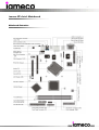
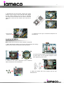
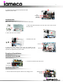
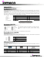
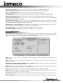
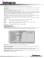
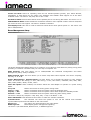
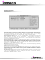
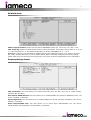
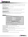
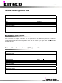
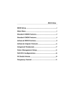
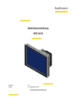
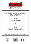
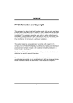
-1-
ecoXPc Installation guide
Copyright © 2007
includes setup, service and
troubleshooting information
-2-
All rights reserved.
™
Copyright © 2007, iamecoP computers.
™
™
MicroPro and the iameco logo are registered
trademarks of Multimedia Computer Systems Ltd and its related entities.
All other trademarks are the property of their respective owners.
Alterations in respect of construction and design, errors and printing errors reserved.
-3-
Environmental issues traditionally confined to certain regions or countries have come to global attention
thanks to treaties aimed at protecting the environment such as the 1989 Montreal Protocol, the United
Nations Framework Convention on Climate Change and the Rio Declaration. In the process, a growing
number of people became aware of the seriousness of environmental degradation stemming from
pollutants and began making efforts to clean up the environment in various industries.
Initially, people paid attention mostly to coping with "end-of-pipe" pollutants in an attempt to minimize
the amount of pollution. Naturally, they relied heavily on highly efficient processing facilities for dealing
with pollutants. However, that method was not able to reduce pollution at the source. Overcoming the
problem requires using fewer raw materials and/or utilizing non-toxic substances. This new approach is
considered a pollution prevention system that is more advanced than the traditional end-of-pipe cleanup
method.
The European Parliament enacted the Directive on Waste Electrical and Electronic Equipment (WEEE),
which defines extended producer responsibility (EPR) regarding electronic and electrical products, and the
Directive on the Restriction of the Use of Certain Hazardous Substances (RoHS), which is designed to ban
the use of specific toxic substances. The two directives are set to take effect in Jan. 2007 and July 2006
respectively. In addition, the European commission proposes a directive on the eco-design of energy-using
products (EuP), which will make it mandatory to consider the environmental impact associated from the
whole life cycle of a product from its designing phase.
These various rules for the development and supply of environmentally friendly products pushed private
enterprises like iameco to come up with integrated product policies (IPP). Businesses are applying IPP to
assess the environmental impact of their products and make improvements as necessary. In so doing, we
make use of LCA and eco-designing techniques with regard to all product-related processes.
Environmentally friendly products require close collaboration and among all entities involved in production,
including end-product producers. For this reason, most end-product producers in the electronics industry
are operating the so-called "green" procurement system (GPS) in an effort to use raw materials and
components that are not harmful to the environment.
In line with the growing popularity of "green" procurement system, electronics manufacturers, many of
who are the customers of iameco, are increasingly demanding eco-products as well as LCA and
environmental information on products. iameco is doing all it can to supply eco-products in order to meet
customer demand.
-4-
First, iameco developed a green computer called the XPc to evaluate and manage eco-product data in a
systematic fashion. Eco Product System (EPS) consists of five modules including LCA, Eco-design, green
purchasing, environmental accounting, and environmental customer treatment. EPS provides LCA data
within a month to the general public and experts. The system will also provide data for environmental
label accreditation and a database on environmental suitability of raw and semi-raw materials. It will
further be used to provide environmental information on work processes, loadings of substance, costs of
products, evaluation of suppliers, and accreditation of eco-partners. In addition, EPS is equipped with the
green procurement capability (for acquiring environmentally friendly raw materials) and Eco-DB (for
providing customers with product-related environmental data in real time).
Second, iameco is supplying eco-products that comply with the EU RoHS Directive (EU RoHS Directive
banned the use of Pb, Hg, Cd, Cr+6, PBB (polybromide biphenyl) and PBDEs (polybrominated diphenyl
ethers in a product). Moreover, we at iameco are continuing our efforts to develop products that do not
require internationally banned toxic chemicals.
Supported by:
-5-
Getting started
You have just purchased a high quality environmentally friendly XPc! Your purchase has contributed to
reducing the burden on the environment and to the further development of environmentally adapted
electronic products.
Please read this manual thoroughly before operating the XPc and keep your user’s manual in an accessible
place at all the times. Make sure the XPc has not been damaged in transit. Before you set up your XPc,
remove any protective film from the outside of it.
Package contents
CPU
Cables
Accessories
Application CD/Disk
Documentation
iameco™ XPc
1 × Power Cord (3)
1 × FDD cable (2)
1 × Power extension cable (9)
1 × ICE Heat-Pipe (1)
1 × Adhesive (5)
2 × cable ties (12)
1 × Cable clip (4)
1 × Heatsink compound (10)
Screws (11)
2 × Motherboard CD Drivers (32bits/64bits) (7)
1 × XPc Extras CD (8)
2 × RAID Driver Floppy Disk (32bits/64bits) (6)
1 × User guide (13)
1 × RAID manual (14)
If any items are missing or damaged, contact your iameco™ dealer.
Warning: Your AC cord comes equipped with a three-wire grounding plug. This plug will fit a standard AC
outlet. If you are unable to insert the plug into an outlet because the outlet isn’t grounded, contact a
licensed electrician to replace the outlet with a properly grounded outlet.
Note: Please keep the box and packing materials in a safe place for re-use. It can be used when
transporting your XPc in the future or return the packaging to iameco for recycling and re-use.
-6-
Getting to know your XPc
Exterior Dissection
1.
2.
3.
4.
5.
6.
7.
8.
9.
5.25" Bay
HDD LED
Power LED
Power
Line-in
Mic
Headphone
USB ports
FireWire® 400 mini port
Note: iameco™ offers a variety of different XPc models loaded with various options. The illustrations here will
help familiarize you with the included features in your new XPc.
Rear connection ports
1.
AC Power socket
2.
COM port
3.
VGA port
4.
FireWire® 400 port
5.
USB Ports
6.
LAN port
7.
PS/2 Mouse
8.
PS/2 Keyboard
9.
Line-In port
10. Central / Bass
11. Rear out(R/L)
12. Front out (R/L)
13. Clear CMOS button
A. Wireless LAN perforation
B. Parallel port perforation
Note: Never force or over-tighten any connectors. If the connectors or ports don’t join with reasonable
ease, they probably don’t match. Make sure that the connectors match the port that you are connecting
and that you have positioned the connector correctly in relation to the ports. Otherwise you may damage
the connections.
The XPc has been designed to be easily configured directly by the end user. The iameco™ XPc owes its
popularity to its unique combination of small-size, high performance and near universal component
compatibility. However, unlike ordinary desktop computers, iameco™ XPc’s have been engineered as
complete systems.
-7-
iameco XPc Intel Mainboard
Mainboard illustration
-8-
XPc Installation Guide
Before you proceed
Take note of the following precautions before you any components or change any the component settings.
Also please read the safety information (discussed on page …) before you plug your PC into a wall socket.
•
Unplug the power cord from the wall socket before touching any component.
Use a grounded wrist strap or touch a safely grounded object or a metal object, such as the power
supply case, before handling components to avoid damaging them due to static electricity.
•
Avoid wearing synthetic fabrics, particularly Nylon.
•
Hold components by the edges to avoid touching the ICs on them.
•
Whenever you uninstall any component, place it on a grounded antistatic pad or in the bag that
came with the component.
Before you install or remove any component, ensure that the ATX power supply is switched off or the
power cord is detached from the power supply. Failure to do so may cause severe damage to the
motherboard, peripherals, and/or components.
Remove the cover
1. Unscrew the three thumbscrews of the chassis cover.
2. Slide the cover backwards and upwards.
Remove the rack
1. Unbuckle the two Serial ATA HDD mounting brackets from
the rack.
2. Remove the rack.
3. Unscrew and remove the front bay covers.
Note: There are 2 screws on each side of the mounting rack.
-9-
CPU and ICE Installation
Remove the ICE Module
1. Unfasten the ICE fan thumbscrews on the back of the
chassis.
2. Unplug the fan power connector.
3. Unfasten the four ICE module attachment
screws.
4. Remove the ICE module from the chassis
and put it aside.
Install the CPU
Note: This 775 pin socket is fragile and easily damaged. Always use extreme care when installing a CPU
and limit the number of times that you remove or change the CPU.
1. Remove the protective cover.
2. First unlock and raise the socket lever, then
open the load plate (be careful not to touch the
socket pins during this process).
- 10 -
3. Orientate the CPU and socket, aligning the yellow
triangle on the corner of the CPU with the triangle
on the socket. Making sure the CPU is perfectly
horizontal; insert the CPU into the socket. Close the
load plate, lower the CPU socket lever and lock in
place.
4. Spread an even layer of thermal compound on
the CPU die.
Install the ICE Module
Note: Please do not use too much Heatsink compound.
1. Place the ICE the module on top of the CPU and align the springloaded screws with the mainboard mounting holes.
2. Screw the ICE module to the mainboard. Note
to press down on the opposite diagonal corner
while tightening each screw.
3. Attach the fan power connector to the extension
cable connected to the mainboard.
4. Fasten the Smart Fan to the chassis with the four
thumbscrews.
- 11 -
DDR Memory Installation
Memory Configuration: Install memory in any or all of the banks according to the combinations shown
below:
Density
Device Width
Single Side
Double Side
TOTAL 2 DIMM up to 2GB and 1GB per DIMM
64 Mbit
128 Mbit
256 Mbit
X8
X16
X8
X16
X8
X16
64MB
64MB
128MB
128MB
256MB
256MB
128MB
128MB
256MB
256MB
512MB
512MB
512 Mbit
X8
X16
512MB
512MB
1024MB
N/A
Note: Double-side X16 DDR-SDRAM chips are not supported by 512M Tech.
Note: 1. Maximum installable memory is 2GB.
2. Registered DIMMs are not supported.
3. Only unbuffered without ECC DIMM are supported.
Note: No jumper settings are required to configure memory.
The system BIOS utility automatically detects the memory settings.
Check the total installed system memory value in the BIOS menu.
Install a DDR module in DIMM1/DIMM2
1. Unlock the DIMM latch.
2. Align the DDR module's cutout with the DIMM slot
notch.
Slide the DDR module into the DIMM slot.
3. Check that the latches are closed, and the DDR
module is firmly installed.
Cable and Rack Installation
Install the FDD Cable
1. Plug the FDD cable in the FDD header (FDD1).
2. Fold the FDD cable under the power supply.
3. Fix the FDD cable to the power and chassis rail
with the supplied adhesive tape.
- 12 -
4. Loosen the purse lock and separate the IDE
HDD/FDD power cable.
Install the Rack
Note: Please make sure to secure the screws on each side.
1. Place the HDD and FDD in the rack and secure with screws
from the side.
2. Place the rack in the chassis.
3. Refasten the rack.
4. Place the power cables in the rack clip located on the
underside of the rack mount then loosen the purse lock and
separate the Optical Drive power cable.
Peripheral Installation
Install the Serial ATA HDD
1. Connect the Serial ATA and power
Install the Floppy Drive
1. Connect the FDD and power cables to the Floppy drive.
- 13 -
Install an Optical Drive
1. Slide the optical drive into the chassis.
2. Fasten the four side screws.
3. Plug the optical drive cable and power cable into the optical
drive.
Note: To prevent exposure to laser emanations (harmful to human eye), do not attempt to disassemble
the unit.
Accessories Installation
Install PCI/ AGP Card
1. A PCI/AGP card will be used to demonstrate the installation
procedure. Unfasten expansion slot bracket screws.
2. Remove the back panel bracket and put the bracket aside.
3. Install the PCI card into the PCI slot.
4. As shown Install the AGP card into the AGP slot.
5. Secure the bracket.
- 14 -
Final Touches
Close the Chassis Cover
1. Replace the cover and refasten the thumbscrews.
2. Complete.
Technical Notes: Clear CMOS Button
On some selected XPcs there is an easy-to-use Clear CMOS Button that allows users to reset BIOS
information to factory default settings.
1
2
3
Power down the XPc and remove the power cord.
Press the Clear CMOS Button by inserting a pointed object (e.g. a
pen nib) into the clear CMOS hole. Keep it pressed for 5 seconds.
Reconnect the power cord and turn on the computer.
Note: Remove the power cord before clearing CMOS.
- 15 -
Jumper Settings
Front Panel Connector (JP9/JP8)
Header JP8 can be used to provide operation status signals to the front daughterboard. Note that this is
an alternative header to the 50pins streamline header that also connects the motherboard to the front
daughterboard.
Headers JP9 is used to connect cable to front panel connector mounted on front-panel or back-panel. The
front panel is where the hard drive activity lights, reset button, on/off button, computer power on light,
USB connectors, 1394 connectors, and audio headers, are located.
Pin
1
2
3
4
5
JP8
HDLED_PU
GLEDA
HDLED
GLEDB
Reset_SW
Pin
6
7
8
9
10
JP8
Power_SW
GND
GND
NC
KEY
Fan Connectors (FAN1/FAN2)
The mainboard provides two onboard 12V cooling fan power
connectors to support CPU (FAN1), System (FAN2) cooling
fans.
Note: Both cable wiring and type of plug may vary depending on the fan maker.
Extended USB Connectors (USB1/USB3)
These headers are used to connect auxiliary USB devices to the mainboard. These headers are directional
and will only allow USB cables to be connected in one direction.
Pin
1
2
3
4
5
USB1/ USB3
GND
GND
Data+
DataVCC
LINE-In(J4), CD-In(CN3), Mini CD-In(CN4) Connectors
Port J4(Blue), CN3(Black) and CN4 can be used to connect a stereo audio input from CD-ROM, TV-tuner or
MPEG card.
Pin
1
2
3
4
J4
Line-in Left
Ground
Ground
Line-in Right
Pin
1
2
3
4
CN3
CD-in Left
Ground
Ground
CD-in Right
Pin
1
2
3
4
CN4
Ground
CD-in Right
Ground
CD-in Left
- 16 -
SPDIF-In/Out Connector (JP4)
Port JP4 can be used to connect special device.
Pin
1
2
3
4
5
6
JP4
SPDIF IN
GND
VCC
GND
VCC
SPDIF OUT
Parallel Port Header-EXT. Printer Port (JP11)
A DB25 male parallel port header is located near the rear panel of the mainboard. The header is used to
connect a parallel port socket (PC8) to the mainboard. The parallel printer port can be purchased from
Shuttle as an optional accessory.
Pin
1
2
3
4
5
6
7
8
9
10
11
12
13
JP11
PSTB
PD0
PD1
PD2
PD3
PD4
PD5
PD6
PD7
P_-ACK
P_BUSY
P_PE
P_SLCT
Pin
14
15
16
17
18
19
20
21
22
23
24
25
26
JP11
PAUTOFD
P_-ERR
PINIT
PSLCTIN
GND
GND
GND
GND
GND
GND
GND
GND
KEY
Startup errors
The BIOS performs a variety of system tests at startup. Serious problems are reported by beep codes. The
red LED is also flashed at the same time as the speaker beep. The BIOS beep codes are as follows:
Beeps
2
3
4
5
6
7
8
9
10
11
Error
Bad external ROM checksum
External ROM initialisation error
No system memory found
Can't boot - no resident language
BIOS ROM checksum error
Bad local RAM
VGA ROM initialisation failure
Invalid system configuration data (or forced default)
No ROM BIOS image found
Corrupted BIOS module found
Note: Please refer to page 15 for BIOS setting information.
- 17 -
BIOS Settings
The BIOS ROM has a built-in setup program that allows users to modify basic system configuration. This
information is stored in battery-backed RAM so that it retains setup information even if the system power
is turned off.
The system BIOS manages and executes a variety of hardware related functions including:
System date and time
Hardware execution sequence
Power management functions
Allocation of system resources
Enter the BIOS
To enter the BIOS (Basic Input / Output System) utility, follow these steps:
Step1. Power on the computer. The system will perform its POST (Power-On Self Test) routine checks.
Step2. Press the <Del> key immediately, or at the following message:
Press DEL to enter SETUP, or simultaneously press <Ctrl>, <Alt>, <Esc> keys
Note 1. If you miss the train of words mentioned in step2 (the message disappears before you can
respond) and you still wish to enter BIOS Setup, restart the system and try again by turning the computer
OFF and ON again or by pressing the <RESET> switch located at the computer’s front-panel. You may also
reboot by simultaneously pressing the <Ctrl>, <Alt>, <Del> keys simultaneously.
Note 2. If you do not press the keys in time and system does not boot, the screen will prompt an error
message, and you will be given the following options: "Press F1 to Continue, DEL to Enter Setup”
Step3. When you enter the BIOS program, the CMOS Setup Utility will display the Main Menu, as shown in
the next section.
The Main Menu
Once you enter the AwardBIOS(tm) CMOS Setup Utility, the Main Menu will appear on the screen. The
Main Menu allows you to select from several setup functions and two exit choices. Use the arrow keys to
select among the items and press <Enter> to accept and enter the sub-menu.
Note that a brief description of each highlighted selection appears at the bottom of the screen.
Setup Items: The main menu includes the following main setup categories. Recall that some systems
may not include all entries.
Standard CMOS Features: Use this menu for basic system configuration.
Advanced BIOS Feature: Use this menu to set the Advanced Features available on your system.
Advanced Chipset Features: Use this menu to change the values in the chipset registers and optimise
your system's performance.
- 18 -
Integrated Peripherals: Use this menu to specify your settings for integrated peripherals.
Power Management Setup: Use this menu to specify your power management settings.
PnP / PCI Configurations: This entry appears if your system supports PnP / PCI.
PC Health Status: This entry displays the current system temperature, Voltage, and FAN settings.
Frequency/Voltage Control: Use this menu to specify your settings for frequency/voltage control.
Load Fail-Safe Defaults: Use this menu to load the BIOS default values for the minimal/stable
performance of your system to operate.
Load Optimized Defaults: Use this menu to load the BIOS default values that are factory-set for optimal
system operation. While Award has designed the custom BIOS to maximize performance, the factory has
the right to change these defaults to meet users' needs.
Set Supervisor / User Password: Use this menu to change, set, or disable password protection. This
allows you to limit access to the system and Setup, or only to Setup.
Save & Exit Setup: Save CMOS value changes in CMOS and exit from setup.
Exit Without Saving: Abandon all CMOS value changes and exit from setup.
Standard CMOS Features
The items in the Standard CMOS Setup Menu are divided into several categories. Each category includes
none, one or more than one setup items. Use the arrow keys to highlight the item and then use the
<PgUp> or <PgDn> keys to select the value you want in each item.
Date: <Month> <DD> <YYYY> Set the system date. Note that the 'Day' automatically changes when you
set the date.
Time: <HH : MM : SS> The time is converted based on the 24-hour military-time clock. For example, 5
p.m. is 17:00:00.
IDE Channel 0 Master/Slave, IDE Channel 2, 3 Master: Options are in its sub-menu. Press <Enter>
to enter the sub-menu of detailed options.
Drive A: Select the type of floppy disk drive installed in your system. The choice: None, 360K, 5.25 in,
1.2M, 5.25 in, 720K, 3.5 in, 1.44M, 3.5 in, or 2.88M, 3.5 in.
Video: Select the default video device. The choice: EGA/VGA, CGA 40, CGA 80, or MONO.
Halt On: Select the situation in which you want the BIOS to stop the POST process and notify you. The
choice: All Errors, No Errors, or All, But Keyboard.
Base Memory:
Displays the amount of conventional memory detected during boot up. The choice: N/A.
Extended Memory: Displays the amount of extended memory detected during boot up. The choice: N/A.
- 19 -
Total Memory: Displays the total memory available in the system.The choice: N/A.
IDE Adapters: The IDE adapters control the hard disk drive. Use a separate sub-menu to configure each
hard disk drive.
IDE HDD Auto-Detection: Press <Enter> to auto-detect HDD on this channel. If detection is successful, it
fills the remaining fields on this menu. Press Enter
IDE Channel 0 Master/Slave, IDE Channel 2, 3 Master: Selecting 'manual' lets you set the remaining fields on
this screen and select the type of fixed disk. "User Type" will let you select the number of cylinders,
heads, etc., Note: PRECOMP=65535 means NONE ! The choice: None, Auto, or Manual.
Access Mode: Choose the access mode for this hard disk. The choice: CHS, LBA, Large, or Auto.
Capacity: Disk drive capacity (Approximated). Note that this size is usually slightly greater than the size of
a formatted disk given by a disk checking program. Auto-Display your disk drive size.
The following options are selectable only if the 'IDE Primary Master' item is set to 'Manual', and Access
mode set to CHS.
Cylinder:
Set the number of cylinders for this hard disk. Min = 0, Max = 65535
Head:
Set the number of read/write heads. Min = 0, Max = 255
Precomp:
Warning: Setting a value of 65535 means no hard disk. Min = 0, Max = 65535
Sector:
Number of sector per track. Min = 0, Max = 255
Landing zone:
Set the Landing zone size. Min = 0, Max = 65535
Advanced BIOS Features
This section allows you to configure your system for basic operation. You have the opportunity to select
the system's default speed, boot-up sequence, keyboard operation, shadowing, and security.
CPU Feature: Press <Enter> to enter the sub-menu of detailed options.
Delay prior to Thermal: This sets the delay time before the CPU enters auto thermal mode. The choice:
None, 1/2/4/8/16/32/64Min.
Thermal Management: This item is select Thermal Management. Thermal Monitor 1 (On die throtting).
Thermal Monitor 2 Ratio & VID transition). The Choice: Thermal Monitor 1 or Thermal Monitor 2.
TM2 Bus Ratio: Represents the frequency (bus ratio of the throttled performance state that will be
initiated when the on-diesensor gose from not hot to hot.
Note: CPU support TM2, item appear.
- 20 -
TM2 Bus VID: Represents the voltageof the throttled performance state that will be initiated when the on
diesensor gose from not hot to hot.
Note: CPU support TM2, item appear.
Limit CPUID MaxVal: Set Limit CPUID MaxVal to 3,Should Be "Disabled" for WinXp. The Choice: Disabled
or Enabled.
Note: Some older O.S.'s (Win98,WinMe..) cannot handle a CPUID MaxVal greater than 3. Please choose
"Enabled" if you use one of those O.S. If your O.S. is WinXP or Win2000, we suggest you "Disabled" the
item.
C1E Function: When disabled, processor can't transitions to a lower core frequency and voltage. The
Choice: Auto or Disabled.
Execute Disable Bit: When disabled, forces the XD feature flag to always return 0. The Choice: Enabled
or Disabled.
Note: CPU support, Execute Disable Bit item appears.
Hard Disk Boot Priority: This item allows you to select Hard Disk Book Device Priority.
Bios Write Protect: This item allows you to enable or disable the Bios Write Protect. If you want to flash
BIOS, you must set it [Disabled]. The choice: Enabled or Disabled.
CPU L1&L2&L3 Cache: All processors that can be installed in this mainboard use internal level1 (L1),
external 2(L2) and (L3) cache memory to improve performance. Leave this item at the default value for
better performance. The choice: Enabled or Disabled.
Note: CPU support, L3 item appear.
Hyper-Threading Technology: The latest Intel application defines a high-speed calculating ability to
optimize your system by two CUPs supported (one virtual, one physical) in a multi-task environment. The
choice: Enabled, or Disabled.
Quick Power On Self-Test: This item speeds up Power-On Self Test (POST) after you power on the
computer. If it is set to enabled, BIOS will shorten or skip some check items during POST. The choice:
Enabled, or Disabled.
First/Second/Third Boot Device: The BIOS attempts to load the operating system from the devices in
the sequence selected in these items. The Choice: LS120, Hard Disk, CDROM, ZIP100, USB-FDD, USBZIP,USB-CDROM, LAN, Disabled or Floppy.
Boot Other Device: If BIOS can't load O.S. from First/Second/Third boot device you select above, BIOS
will search other devices and attempt to load O.S. The choice: Enabled or Disabled.
Boot Up Floppy Seek: Seeks disk drives during boot-Up. Disabling speed boots up. The choice: Enabled
or Disabled.
Boot Up NumLock Status: Selects power on state for NumLock. The choice: Off or On.
Gate A20 Option: This entry allows you to select how the Gate A20 is handled. The gate A20 is a device
used for above 1MByte of address memory. Initially, the gate A20 was handled via a pin on the keyboard.
Today, while a keyboard still provides this support, it is more common and much faster in setting to fast
for the system chipset to provide support for gate A20. The choice: Normal or Fast.
Security Option: Select whether the password is required every time the system boots or only when you
enter setup.
System The system will not boot and access to Setup will be denied if the correct password is not entered
promptly.
Setup The system will boot, but access to Setup will be denied if the correct password is not entered
promptly.
The choice: System or Setup.
Note: To disabled security, select PASSWORD SETTING at Main Menu, and then you will be asked to enter
password. Don't type anything and just press <Enter>; it will disable security. Once the security is
disabled, the system will boot, and you can enter Setup freely.
APIC Mode: Via the routing, I/O APIC supports a total of 24 interrupts. We recommend to choose
[Enabled] for Windows XP and Windows 2000. The choice: Enabled or Disabled.
MPS Version Control For OS: Selects the operating system multiprocessor support version. The choice:
1.1 or 1.4
- 21 -
Advanced BIOS Chipset Features
This section allows you to configure the system based on the specific features of the installed chipset. This
chipset manages bus speeds and access to system memory resources, such as DRAM and the external
cache. It also coordinates communications between the conventional ISA bus and the PCI bus. It states
that these items should never need to be altered.
The default settings have been chosen because they provide the best operating conditions for your
system. If you discovered that data was being lost while using your system, you might consider making
any changes.
DRAM Clock/Timing Control: Press <Enter> to enter the sub-menu of detailed options.
Performance Mode: This item allows you to enable/disable the performance mode. The Choice: Enabled, or
Disabled.
DRAM Timing Control: This item allows you to select the value in this field, depending on whether the
board using which kind of DDR DRAM. The Choice: By SPD or Manual.
DRAM CAS Latency: The Choice: 2T, 2.5T or 3T.
RAS Active Time(tRAS): The Choice: 4T, 5T, 6T, 7T, 8T or 9T.
RAS Precharge Time(tRP): The Choice: 2T, 3T, 4T or 5T.
RAS to CAS Delay(tRCD): The Choice: 2T, 3T, 4T or 5T.
APG & P2P Bridge Control: Press <Enter> to enter the sub-menu of detailed options.
AGP Aperture Size (MB): Select the size of Accelerated Graphics Port (AGP) aperture. The aperture is a
portion of the PCI memory address range dedicated to graphics memory address space. Host cycles that
hit the aperture range are forwarded to the AGP without any translation. The Choice: 32M, 64M, 128M,
256M or 512M.
Graphic Window WR Combine: This item enable/disable the write combine function for Graphic address
space. The Choice: Enabled or Disabled.
AGP Fast Write Support: This item enable/disable the AGP fast write support. The Choice: Enabled or
Disabled.
AGP Data Rate: This item allows the user to adjust AGP data rate. The Choice: Auto, 1X, 2X, 4X, 8X.
OnChip AGP Control: Press <Enter> to enter the sub-menu of detailed options.
VGA Share Memory Size: This item allows the user to adjust VGA share memory size. The Choice: 16MB,
32MB, or 64MB.
System BIOS Cacheable: Selecting Enabled allows caching for the system BIOS ROM at F0000h-FFFFFh,
resulting in better system performance. However, if any program is written to this memory area, a system
error may result. The Choice: Enabled or Disabled.
Video RAM Cacheable: Selecting Enabled allows caching of the video RAM, resulting in better system
performance. However, if any program is written to this memory area, a system error may result. The
Choice: Enabled or Disabled.
Memory Hole at 15M-16M: You can reserve this area of system memory for ISA adapter ROM. When
this area is reserved, it cannot be cached. The user information of peripherals that need to use this area of
system memory usually discusses their memory requirements. The Choice: Enabled or Disabled.
- 22 -
Integrated Peripherals
SIS Onboard IDE Device: Press <Enter> to enter the sub-menu of detailed options.
Internal PCI/IDE: This chipset contains and internal PCI IDE interface with support for two IDE channels.
The choice: Disabled, Primary, Secondary, or Both.
IDE Primary Master/Slave PIO: The four IDE PIO (Programmed Input/Output) fields let you set a PIO mode
(0-4) for each of the four IDE devices that the onboard IDE interface supports. Modes 0 through 4 provide
successively increased performance. In Auto mode, the system automatically determines the best mode
for each device. The choice: Auto, Mode 0, Mode 1, Mode 2, Mode 3, or Mode 4.
Primary Master/Slave UltraDMA: Ultra DMA/100 implementation is possible only if your IDE hard drive
supports it and the operating environment includes a DMA driver (Windows 95 OSR2 or a third-party IDE
bus master driver). If both of your hard drive and your system software support Ultra DMA/133/100,
select Auto to enable BIOS support. The choice: Auto or Disabled.
SIS Onboard PCI Device: Press <Enter> to enter the sub-menu of detailed options.
SIS USB Controller: Select Enabled if your system contains a Universal Serial Bus (USB) controller and you
have USB peripherals. The choice: Enabled or Disabled.
USB 2.0 Supports: Select Enabled if your system contains a Universal Serial Bus 2.0 controller and you have
USB peripherals. The Choice: Enabled or Disabled.
SiS AC97 Audio: This item allows you to control the onboard AC97 Audio. The Choice: Enabled or Disabled.
SiS Serial ATA Controller: Use this item to enable or disable the SiS Serial ATA Controller. The Choice:
Enabled or Disabled.
SiS Serial ATA Mode: This item allows you to set the SATA Mode. The Choice: IDE or RAID.
Onboard LAN Boot ROM: Decide whether to invoke the boot ROM of the onboard LAN chip. The choice:
Enabled or Disabled.
Onboard Super IO Device: Press <Enter> to enter the sub-menu of detailed options.
Onboard FDC Controller: Select Enabled if your system has a floppy disk controller (FDC) installed on the
system board and you want to use it. If you install add-on FDC or the system has no floppy drive, select
Disabled in this field. The choice: Enabled or Disabled.
Onboard Serial Port1: Select an address and corresponding interrupt for the first and second serial ports.
The choice: 3E8/IRQ4, 2E8/IRQ3, 3F8/IRQ4, 2F8/IRQ3, Auto, or Disabled.
Onboard Parallel Port: This item allows you to determine onboard parallel port controller I/O address
setting. The Choice: 378/IRQ7, 278/IRQ5, 3BC/IRQ7 or Disabled.
- 23 -
Parallel Port Mode: Select an operating mode for the onboard parallel (printer) port. Select Normal,
Compatible, or SPP unless you are certain your hardware and software both support one of the other
available modes. The Choice: SPP, EPP, ECP or ECP + EPP.
ECP Mod Use DMA: Select a DMA channel for the parallel port for use during ECP mode. The Choice:1 or 3.
IDE HDD Block Mode: Select Enabled for automatic detection of the optimal number of block read/write
per sector the drive can support. The Choice: Enabled or Disabled.
Init Display First: This item is used to determine initial device when system power on. The choice: PCI
Slot or AGP/Onboard.
Power Management Setup
The Power Management Setup allows you to configure your system to most effectively saving energy while
operating in a manner consistent with your own style of computer use.
ACPI Function: This item allows you to enable/disable the Advanced Configuration and Power
Management (ACPI). Always "Enabled".
ACPI Suspend Type: This item allows you to select sleep state when suspend. The choice: S1(POS),
S3(STR), or S1 & S3.
Power Management / Suspend Mode: This item allows you to decide the timing to enter suspend
mode. The choice: Min Saving / 1 Hour, Max Saving / 1 Min, User Define / Disabled, 1Min, 2Min, 4Min,
8Min, 12Min, 20Min, 30Min, 40 Min, 1Hour.
Video Off Option: When enabled, this feature allows the VGA adapter to operate in a power saving
mode.
Always On
Monitor will remain on during power saving mode.
Suspend --> Off
Monitor is blanked when the system enters the Suspend mode.
Susp,Stby --> Off
Monitor is blanked when the system enters either Suspend or Standby modes.
All Modes --> Off
Monitor is blanked when the system enters any power saving mode.
The choice: Always On, Suspend ->Off, Susp, stby -> Off, or All Modes -> Off.
Video Off Method: This determines the manner in which the monitor is blanked.
V/H SYNC+Blank:
This selection will cause the system to turn off the vertical and horizontal
synchronization ports and write blanks to the video buffer.
Blank Screen:
This option only writes blanks to the video buffer.
DPMS Supported:
Initial display power management signaling.
The choice: V/H SYNC+Blank, Blank Screen, or DPMS Supported.
- 24 -
Switch Function: Enables you to set the System Management Interrupt (SMI) button function in DOS.
The choice: Disabled or Break /wake.
MODEM Use IRQ: This determines the IRQ which the MODEM can use. The choice: 3, 4, 5, 7, 9, 10, 11,
or Auto.
HDD Off After: The IDE hard drive will spin down if it is not accessed within a specified length of time.
Options are from 1 Min to 15 Min and Disable.The choice: Disabled, 1 Min ~ 15 Min.
Power Button Override: Pressing the power button for more than 4 seconds forces the system to enter
the Soft-Off state when the system has "hung." The choice: Instant-Off or Delay 4 Sec.
Power State Resume Control: This item enables your computer to automatically restart or return to its
last operating status after power returns from a power failure. The choice: Always Off, Always On, Keep
Pre-state.
PM Wake Up Events: Press <Enter> to enter the sub-menu of detailed options.
IRQ [3-7, 9-15], NMI: When enabled, any event occurring at IRQs 3 through 15 (excluding IRQ 8) will
awaken a system, which has been powered down. The choice: Enabled, Disabled.
IRQ 8 Break Suspend: This field allows you to enable or disable monitoring of IRQ8 so that it does not
awaken the system from a suspend mode. The choice: Enabled, Disabled.
RING Power Up Control: When set to Enabled, the system power will be turned on if there is any modem
activity. The choice: Enabled, Disabled.
PCIPME Power Up Control: When set to Enabled, system power will be turned on if there is any PCI card
activity from PCI cards that trigger a PME event, such as LAN or Modem cards. The choice: Enabled,
Disabled.
PS2KB Power Up Control: When Select Password, Please press ENTER key to change Password Max 8
numbers. If Select Password, and press Enter twice it mean KB Power On Function Disable. Hot Key:
Alt+Ctrl+<- The choice: Hot key, Password, Any key.
PS2MS Power Up Control: This item selects the PS2MS Power Up Control. The choice: Disabled, Click, Move
& Click.
Power Up by Alarm: When set to Enabled, the following three fields become available and you can set the
month, date (day of the month), hour, minute and second to turn on your system. The choice: Enabled,
Disabled.
Month Alarm: This is for specifying the alarm month which system will awaken the system from suspend
mode. The choice: NA, 1 ~ 12. Day of Month Alarm: This item selects the alarm date. Key in a DEC
number: Min=0, Max=31.
Time (hh : mm : ss) Alarm
This item selects the alarm Time. [hh] Key in a DEC number: Min=0, Max=23. [mm/ss] Key in a DEC
number: Min=0, Max=59.
** Reload Global Timer Events **
Global Timer (power management) Events are I/O events whose occurrence can prevent the system from
entering a power saving mode or can awaken the system from such as a mode. In effect, the system
remains alert for anything that occurs to a device that is configured as Enabled, even when the system is
in a power-down mode.
Primary/Secondary IDE: When these items are enabled, the system will restart the power-saving timeout
counters when any activity is detected on any of the drives or devices on the primary or secondary IDE
channels. The choice: Disabled or Enabled.
FDD,COM,LPT Port: When this item is enabled, the system will restart the power-saving timeout counters
when any activity is detected on the floppy disk drive, the serial ports, or the parallel port. The choice:
Disabled or Enabled.
PCI PIRQ[A-D]# : When this item is disabled, any PCI device set as the Master will not power on the
system. The choice: Disabled or Enabled.
- 25 -
PnP/PCI Configurations
This section describes the configuration of PCI bus system. PCI or Personal Computer Interconnection is a
system which allows I/O devices to operate at the speed CPU itself keeps when CPU communicating with
its own special components. This section covers some very technical items, and it is strongly
recommended that only experienced users should make any changes to the default settings.
Reset Configuration Data: Normally, you leave this field Disabled. Select Enabled to reset Extended
System Configuration Data (ESCD) when you exit from Setup if you have installed a new device or
software and the system reconfiguration has caused such a serious conflict that the operating system
cannot boot. The choice: Enabled or Disabled.
Resource controlled By: The Award Plug-and-Play BIOS has the capacity to automatically configure all of
the boot and Plug-and-Play compatible devices. However, this capability means absolutely nothing unless
you are using a Plug-and-Play operating system such as Windows 95. If you set this field to "manual”,
choose specific resources by going into each of the sub-menu that follows this field (a sub-menu is
proceeded by a ">"). The choice: Auto (ESCD) or Manual.
IRQ Resources: When resources are controlled manually, assign each system interrupt a type, depending
on the type of device using the interrupt.
IRQ3/4/5/7/9/10/11/12/14/15 assigned
This item allows you to determine the IRQ assigned to the ISA bus and is not available to any PCI slot.
Legacy ISA for devices is compliant with the original PC AT bus specification; PCI/ISA PnP for devices is
compliant with the Plug-and-Play standard whether designed for PCI or ISA bus architecture. The choice:
PCI Device or Reserved.
PCI/VGA Palette Snoop: It determines whether the MPEG ISA/VESA VGA Cards can work with PCI/VGA
or not. If you have MPEG ISA/VESA VGA Cards and PCI/ VGA Card worked, Enable this field. Otherwise,
please Disable it. The choice: Enabled or Disabled.
- 26 -
PC Health Status
CPU Fan Speed Control: Set the CPU Fan Speed. The choice: Smart Fan, Ultra-Low, Low, Mid, or Full.
CPU Temp Tag: Enabled 3-phase smart control to the Selected fan. This feature ranges from 25 °C to 75
°C, in an increment of 1°C. The default temperature is at 60°C. The choice: 25 °C ~ 75 °C.
Warning: It is Strongly recommended to disable CPU Fan Auto Guardian feature, if you wish to use other
fan cooler, allowing the fan to run at its default speed. Before manually modifying the CPU fan setting,
please make sure fan connectors are plug into the correct fan connector designations on the mainboard.
Frequency/Voltage Control
CPU Clock Ratio: This item allows you to adjust CPU Ratio. Min: 8X, Max: 50X. Key in a DEC number:
(Between Min and Max.)
Auto Detect DIMM/PCI Clk: This item allows you to enable/disable auto detection DIMM/PCI Clock. The
choice: Enabled, or Disabled.
Spread Spectrum: This item allows you to enable/disable the spread spectrum modulation. The choice:
Enabled, or Disabled.
Async AGP/PCI/SRC C1K: This item allows you to select Async AGP/PCI/SRC C1K. The choice:
66/33/100MHz, 80/40/100MHz, 72/36/100MHz, or Disabled.
- 27 -
CPU Frequency: This item allows the user to adjust CPU Host Clock. Min: 133, Max: 232. Key in a DEC
number: (Between Min and Max.)
CPU: DRAM Frequency Ratio: This item allows you to adjust CPU and DRAM Ratio. The choice: SPD,
1:1, 3:4, 3:5, 1:2.
DRAM Frequency: This item shows DRAM frequency.
Load Fail-Safe Defaults
When you press <Enter> on this item, you will get a confirmation dialog box with a message similar to:
Load Fail-Safe Defaults (Y/N) ? N
Pressing 'Y' loads the BIOS default values for the most stable, minimal system performance.
Load Optimized Defaults
When you press <Enter> on this item, you will get a confirmation dialog box with a message similar to:
Load Optimized Defaults (Y/N) ? N
Pressing 'Y' loads the default values that are factory-set for optimal system performance.
Set Password
This item is to set a supervisor password. Please follow below steps.
New Password Setting:
1. Press the <Enter> key. A dialog box appears to ask you to “Enter password:”
2. Key in a new password.
The password cannot be over eight characters or numbers.
3. The system will then request you to confirm the new password by asking you to key in the new
password again.
4. Once the confirmation is completed, new code is in effect.
No Password Setting:
5. If you want to delete the password, just press the <Enter> key instead of typing a new password.
Follow the procedure as above.
If You Forget Password:
6. If you forget your password, you must turn off the system and clear CMOS.
- 28 -
Save & Exit Setup
Press <Enter> on this item to save your changes. The system will ask for confirmation : system
Save to CMOS and EXIT (Y/N)? Y
Pressing "Y" stores the selections made in the menus of CMOS - a special section of memory that stays on
after you turn your system off. The next time you boot your computer, the BIOS configures your system
according to the Setup selections stored in CMOS. After saving the values the system will restart.
Exit Without Saving
Press <Enter> on this item to exit without saving changes. The system will ask for confirmation:
Quit without saving (Y/N)? Y
This allows you to exit from Setup without storing in CMOS any change. The previous selections remain in
effect. This exits from the Setup utility and restarts your computer.
Tips and Safety precautions
For your safety and the safety of your equipment, please read and observe the following rules, as well as
the guidelines for working more comfortably.
Location and installation
•
•
•
•
•
•
•
•
Set down the XPc carefully on a flat and stable work surface. The XPc can cause injury by falling as a
result of placing on top of unstable objects or in unsafe places.
Do not use the XPc where the ventilation is poor, or there’s a lot of dust, where humidity is high, or
where the XPc may come into contact with oil or steam and do not place the XPc where the power cord
is subject to damage.
The vents and other openings in the cabinet are designed for ventilation. Do no cover these vents and
openings since insufficient ventilation can cause overheating and/or shorten the life of the XPc. Do not
place the XPc on a bed, sofa, rug, or other similar surface, or in an enclosed space since they can
block the ventilation openings.
Ensure that the XPc does not come into contact with water or other fluids and protect your computer
from dampness or wet weather, such as rain, snow. Ensure that no objects such as paper clips or pins
enter the XPc as this could lead to fire or electric shock.
Do not allow the XPc to come into contact with strong shocks or vibrations. Causing the XPc to fall or
topple over may damage it.
Do not place any heavy objects on the XPc. This may cause an electric shock or a fire.
Do not use in places where the XPc will be subject to direct sunlight, near heating equipment or
anywhere else where there is likelihood of high temperature, as this may lead to generation of
excessive heat and outbreak of fire.
Remove all electronic devices or anything with strong magnetic fields such as radios, fans, clocks and
telephones that are within 3 feet (one meter) of the XPc.
- 29 -
Power
•
•
•
•
•
•
•
•
•
When connecting to the power socket ensure that it is firmly connected. Do not use a damaged or
loose plug or socket.
Use only a properly grounded plug and receptacle. An improper ground may cause electric shock or
equipment damage.
Keep the minimum required distance between the power cord and any heat sources.
Do not connect too many extension cords to an outlet. Insert the power plug directly into the AC
outlet.
Do not excessively bend the plug and wire nor place heavy objects upon them. Doing so may cause an
electric shock.
Disconnect the plug from the outlet during storms or lightening or if it is not used for a long period of
time.
Do not pull the plug out by the wire nor touch the plug with wet hands.
Electrical equipment may be hazardous if misused. An adult must always supervise operation of this
product. Do not allow children access to the interior of any electrical product and do not permit them
to handle any cables.
Do not attempt to repair the power cord if it is broken or malfunctioning. Refer the servicing to your
iameco™ service representative.
Note: There are dangerous high voltages inside, even when the power is OFF. The only way to turn off
power completely is to disconnect the power cord. Make sure at least one end of the power cord is within
easy reach so that you can unplug the XPc when you need to. Use only the power cord supplied with the
CPU.
Other safety instructions
•
•
•
•
•
•
Do not place liquids, chemicals or any metal objects on the XPc. This may cause damage, electric
shock or a fire. If a foreign substance gets into the XPc, disconnect from AC power and then contact
iameco™ service centre.
Before you lift or reposition your XPc, disconnect all cables and cords connected to it.
Do not move the XPc by pulling the wire or the signal cable.
Do not add accessories that have not been designed for this XPc.
Keep the XPc away from any magnetic substances.
Never rub or tap the XPc with hard objects.
Repair of your iameco™ XPc
All spare parts are available from iameco™ and can only be installed by official service centres. Visit
www.iameco.com for updated information.
If your XPc is not operating normally or if there are any unusual sounds or smells coming from it, unplug it
immediately and contact your iameco™ service centre.
Before contacting us
In many cases, your monitor may not need repair. Before you contact us, please consult the
troubleshooting section to see if you can easily remedy the problem yourself. Refer to page no 24. You
can find the addresses of iameco™ service centres in page no 37.
MicroPro Computers
98 Nutgrove Avenue,
Rathfarnham,
Dublin 14,
Ireland.
Tel: +353 (0) 1 4930514
Fax: +353 (0) 1 4943885
- 30 -
Disposal information
The PC housing is manufactured of recycled aluminium, thereby exceeding the reuse and recycling facility.
This also maximises energy saving, as minimal additional energy is required for re-manufacture with
recycled aluminium. No plastic is used in the computer housing. Reusable materials and recyclable
packaging are also used, resulting in zero waste. It’s a modular design, which means you can take out and
replace an individual part when it fails, as opposed to the whole machine maximising the options for
upgrading and reuse of the PCs. At the end of life of your iameco™ product we recommend that you treat
the disposal of your equipment in an environmentally sound manner. Potential methods include reuse of
parts or whole products and recycling of products, components and/or materials.
By any means, this equipment should not be disposed in an ordinary dustbin with household waste! Be
responsible for your environment!
Information on disposal for private households
In the European Union (EU)
Ideally, the first option would be to bring back your iameco™ product to iameco™ service centre for
remanufacture.
In some countries, your local retailer may also take back your old product free of charge if you purchase a
similar new one. Please contact your local authority for further details. If your used electrical or electronic
equipment has batteries or accumulators, please dispose of these separately beforehand according to local
requirements. By disposing of this product correctly you will help ensure that the waste undergoes the
necessary treatment, recovery and recycling and thus prevent potential negative effects on the
environment and human health which could otherwise arise due to inappropriate waste handling.
In other countries outside the EU
If you wish to discard this product, please contact your local authorities and ask for the correct method of
disposal. In some countries used electrical or electronic equipment can be returned free of charge to the
dealer, even if you don’t purchase a new product.
Information on disposal for business users
In the European Union (EU)
If the product is used for business purposes and you want to discard it please contact your iameco™ dealer
who will inform you about the take-back of the product. You might be charged for the costs arising from
the take-back and recycling. Small products (and small amounts) might be taken back by your local
authority for take-back of your used products.
In other countries outside the (EU)
If you wish to discard of this product, please contact your local authorities and ask for the correct method
of disposal.
WEEE collection points in Dublin, Ireland
There are 7 recycling centres located in Dublin, which will take back your Waste Electrical and Electronic
Equipment (WEEE) for free.
Shamrock Terrace Recycling Centre (North Strand) - Dublin City Council
Pigeon House Recycling Centre, Ringsend - Dublin City Council
Balleally Recycling Centre - Fingal County Council
Coolmine Recycling Centre - Fingal County Council
Balbriggan Recycling Centre - Fingal County Council
Ballyogan Recycling Centre - Dun Laoghaire Rathdown County Council
Ballymount Recycling Centre - South Dublin County Council
- 31 -
Return Policy
Our guarantee
iameco™ is pleased to offer you a 7-day money back guarantee if you are not fully satisfied with our
products (subject to certain conditions contained in this return policy). You have 7 days from date of
shipment of your purchase to return your purchase. iameco™ must be notified by e-mail of your intention to
return your purchase within 10 days of shipment.
How to return your purchase
All returns queries are dealt with by e-mail. Contact [email protected] for further instructions. You will
be e-mailed a Return Merchandise Authorisation (RMA) number with some details to fill out before
receiving the RMA number. You can find the RMA form on page 36 in this manual.
Exchanges
Exchange of items is handled in the same way as returns. However there is a charge on freight cost to
ship it out again. You will be informed how to process this charge. Replacement items are not entitled to
free delivery even if the free shipping option was included in the original order.
Returns - Exchanges Terms and Conditions
iameco will repair/exchange/replace the full original product. Price including original shipping costs if the
return is as a result of an iameco error.
If the product fails within the manufacturer's Dead on Arrival (DOA) period, a replacement product will be
offered.
iameco™ is NOT responsible for any loss or damage of your return.
Any non-insured, items showing wear and tear or damage will not be accepted for return. Returned items
must be in a re-saleable condition. Please ensure that items are insured for the full amount including
shipping costs. iameco™ will not be liable for any shipping charges on the returned items.
All original paperwork and documentation must be included. Custom requests, special orders are not
accepted for return. We reserve the right not to accept any item that has not been hallmarked as a result
of a special request. Items will not be accepted for return after 10 days from shipping date.
Packing your return
Pack your return carefully in the original boxing. Include all original paperwork and documents. Send the
package by priority registered mail or a shipment of your choice to
MicroPro Computers
98 Nutgrove Avenue,
Rathfarnham,
Dublin 14,
Ireland.
Tel: +353 (0) 1 4930514
Fax: +353 (0) 1 4943885
Mark your Returns Material Authorisation (RMA) number clearly on the outside. Mark clearly on the
outside that this is an item originally exported from Ireland and now being returned. Request a return
receipt to confirm that we have received your item.
- 32 -
Warranty information
The following terms apply only to new "in the original carton" products marketed and distributed by
iameco™, which are purchased and used by the original consumer purchaser. This information is subject to
the terms and conditions of the written warranty statement included with each product, and are available
for examination from the dealer prior to purchase.
Depending on the model, your terms and conditions may be different from those shown below, and this
information is subject to change without prior notice. Unless specifically stated otherwise, used and
reconditioned products that are resold have no warranty from iameco™ and are considered sold "AS-IS",
however, the selling dealer may offer additional service options.
Information in this document is subject to change without prior notice.
Reproduction in any manner whatsoever without the written permission of iameco™ is strictly forbidden.
iameco™ shall not be liable for errors contained herein or for incidental or consequential damages in
connection with the furnishing, performance, or use of this material.
Warranty for iameco™ XPc
Product
iameco XPc
XPC
1 Year
Labour
1 Year
Parts
1 Year
What the warranty covers
iameco™ warrants your display(s) against defects in material and workmanship during the warranty period
from iameco™ factory delivery date shown the in shipping documents. If a product proves to be defective in
material or workmanship during the warranty period, iameco™ will, at its sole option repair or replace the
product with similar product provided the purchaser adheres to certain return authorization procedures
and guidelines. iameco™ may, use rebuilt, reconditioned, or new parts or components when repairing any
product or replace a product with a rebuilt, reconditioned or new product. Upon request from iameco™, the
consumer must provide information to reasonably prove the date of purchase. iameco™ reserves the right to
charge customer in case of warranty conditions that are not fulfilled.
How long the warranty is effective
iameco™ display products are warranted for 1 year for LCD Panel, 2 years for parts and labour, starting
from the delivery date as per shown on the corresponding shipping documents. Please ensure you register
your iameco™ product to avail of your guarantee.
Who the warranty protects
This warranty is valid only for the first purchaser and is not assignable or transferable to any subsequent
purchaser/end user.
What the warranty does not cover for
1.
2.
Any product, which the serial number has been defaced, modified or removed.
Damage, deterioration or malfunction resulting from:
a. Accident, misuse, neglect, fire, water, lightning, or other acts of nature, Power Indicator
Green/Orange, blinking, No light, unauthorized product modification, or failure to follow
instructions supplied with the product will not be covered under warranty.
b. Repair or attempted repair by anyone not authorized by iameco™.
c. Any damage of the product due to shipment.
d. Removal or installation of the product.
e. Causes external to the product, such as electric power fluctuations or failure.
f. Use of supplier or parts not meeting iameco™ specifications.
g. Normal wear and tear.
h. Any other cause that does not relate to a product defect.
- 33 -
3.
4.
5.
6.
7.
8.
9.
Cosmetic damage by purchaser, such as markings, discolouration, scratches, dents, anti-theft devices
markings, gouges or any other defacement.
Physically damaged products by purchaser, such as broken PCB, Housing, damaged LCD Module.
No Defect Found (product returned to iameco™ as defective but failure is not duplicated by iameco™'s
test method).
The product is not in accordance with the fault in the application.
Damage resulting from use of non- iameco™ approved accessories.
Timber is a lifelike natural material which can cause some little changes in the precision of the
produced product such as small openings line beside the connecting point and some other small
changes which are out of iameco™ control and don't make any effect for the product functionality.
Products serviced by non-authorized persons or companies.
Limitation of liability
If your iameco™ product fails to work as warranted above, your sole and exclusive remedy shall be repaired
or replaced. iameco™ maximum liability under this limited warranty is expressly limited to the lesser of the
price you have paid for the product or the cost of repairing or replacement of any hardware components
that malfunction in conditions of normal use.
iameco™ is not liable for any damages caused by the product or the failure of the product to perform,
including any lost profits or savings or special incidental, or consequential damages. iameco™ is not liable for
any claim made by a third party or made by you for a third party.
This limitation of liability applies whether damages are sought, or a claim made, under this limited
warranty or as a tort claim (including negligence and strict product liability), a contract claim, or any other
claim. This limitation of liability cannot be waived or amended by any person. This limitation of liability will
be effective even if you have advised iameco™ or an authorized representative of iameco™ of the possibility of
any such damages.
This limitation applies whether damages are sought, or a claim made, under this limited warranty or as a
tort claim (including negligence and strict product liability), a contract claim, or any other claim. This
limitation of liability cannot be waived or amended by any other person. This limitation of liability will be
effective even if you have advised iameco™ or an authorized representative of iameco™ of the possibility of
any such damages. This limitation of liability however will not apply to claims for personal injury.
How to get warranty service
1.
For information on obtaining warranty service, contact your iameco™ dealer (the place where you
bought your product) as your first choice. If for any reason you can not contact your dealer, please
contact iameco™ customer service by emailing to [email protected]
2.
To obtain warranty service, you will be required to fill out RMA Request Form (return
merchandise/material authorization) available on page 36 of the user's manual, or on the following
address (www.iameco.com/support/rma.htm) to provide:
i. Your information
ii. Reference of your purchase and copy of your invoice confirming your warranty
iii. Product information
iv. A description of the problem
If the contact is made with iameco™ Customer Service, iameco™ will contact the customer upon receipt of the
RMA Request Form and issue a RMA number within normally 48-72 hours and give the customer further
instructions.
iameco™ technical support services
During the period of product warranty, we support your basic configuration, setup and troubleshooting
questions, and when required, we provide you with all instructions on how to return your product for
repair. For support enquiries, please e-mail us at [email protected]
Note: RMA programme is subject to changes at any time without prior notice.
Conditions: The above policies are for warranty service and the customer will be responsible for any costs
associated with non-warranty conditions such as control test, shipping and administration costs, etc.
- 34 -
Regulatory Notices
ENERGY STAR® Compliance
iameco™ products are designed to minimize energy consumption and meet
requirements set by ENERGY STAR®. Our monitors are EPA ENERGY STAR®
compliant and ENERGY 2000 compliant when used with a computer equipped with
DPMS functionality. iameco™ has determined that this product meets with the
Environmental Protection Agency (EPA) ENERGY STAR® guidelines as configured.
You can help reduce electricity usage and its side effects by turning off your
product when it is not in use for extended periods of time, particularly at night and
on weekends.
TCO’99 Qualifications (Sweden)
Certain iameco™ products have achieved TCO’99 qualification. Qualified products
meet the requirements for the TCO’99 scheme, which provides for international and
environmental labelling of personal computers. The labelling scheme was developed
as a joint effort by the TCO (the Swedish Confederation of Professional Employees),
Svenska Naturskyddsforeningen (the Society for Nature Conservation).
Approval requirements cover a wide range of issues: environment, ergonomics,
usability, emission of electric and magnetic fields, energy consumption and electric
and fire safety. Current information regarding TCO’99 approved and labelled
products may be obtained from the address: www.tcodevelopment.com
Eco-Flower
The European Union's eco-labelling programme was launched throughout the
European Community in 1993 to encourage the manufacture of less
environmentally damaging products. The European Union's Eco-label, a flower with
the EU’s star symbol, is awarded to products that have passed a life cycle analysis.
Further information on the eco-label can be found at http://europa.eu/int/ecolabel
Restriction of Hazardous Substances (RoHS)
iameco products are safe from hazardous substances (Cd, Pb, Hg, Cr+6, PBDE and
PBB) and can be disposed of in an environmentally safe manner. Moreover, we at
iameco are continuing our efforts to develop products that do not require
internationally banned toxic chemicals. The parts and components have been
carefully selected to meet RoHS requirements and to minimise electricity
consumption, electromagnetic emissions and noise.
Waste Electrical & Electronic Equipment (WEEE)
iameco has been registered by the WEEE Registration Society Limited in accordance
with provisions of article 12(5) of the Waste Management (Waste Electrical &
Electronic Equipment) Regulations 2005 (S.I. No. 340 of 2005) with the
registration number is 00823. Used electrical and electronic equipment must be
treated separately and in accordance with legislation that requires proper
treatment, recovery and recycling of used electrical and electronic equipment to
designated collection facilities free of charge.
- 35 -
ISO certifications
ISO 9001:2000
iameco has been assessed and is in compliance with the provisions of the Quality
System to IS.EN.ISO 9001:2000 in respect of the scope of operations such as build
and sale of environmentally friendly computers. Service and repair of computers,
peripherals and network solutions and is hereby included in the European Quality
Assessment (EQA) directory of certified organisations. This certificate of Quality
System Registration Number 3176 was issued on 2nd November 2006 and is valid
until 1st November 2009.
ISO 14001:2004
The European Quality Assessment (EQA) granted iameco whose Environmental
Management System is in conformance with ISO 14001:2004 the right to be listed
in the Environmental Register of Assessed Companies for the following scopes:
build and sale of environmentally friendly computers, service and repair of
computers, peripherals and network solutions. This certificate of Assessment
Number 7173 was issued on 27th November 2006 and is valid until 26th November
2009.
Supported by
- 36 -
iameco™ Product registration form
Title
Contact first name
Contact last name
Address/Company
City
Daytime phone
E-mail address
Reference number*
Purchase date
Dealer
Country
Fax
* Can be found at the back of the XPc
Registering your iameco™ product
Upon receipt of your Product Registration you will be enrolled in the iameco™ programme at no additional
cost, which will enable you to receive technical support and iameco™ newsletters periodically. Failure to
complete and submit this product registration form will not diminish your rights under iameco™ Standard
Limited Warranty.
You can either e-mail it to [email protected] or fax it to +353 (0) 1 4943885.
Returns Material Authorisation (RMA) request form
Title
Contact first name
Contact last name
Address/Company
City
Daytime phone
E-mail address
Unit description
Reference number
Model ID
Serial number(s)*
Purchase date
Dealer
Description of fault
* i.e. “Invoice Number”, “Order Number”, etc
Country
Fax
- 37 -
iameco™ registered dealers in Ireland
MicroPro Computers
Cultivate Sustainable Living Centre
98 Nutgrove Avenue,
Rathfarnham,
Dublin 14,
Ireland.
15-19 Essex St,
West Temple Bar,
Dublin 8,
Ireland.
Tel: +353 (0) 1 4930514
Fax: +353 (0) 1 4943885
Homepage: www.micropro.ie
E-mail: [email protected]
Contact: Paul Maher
Tel: +353 (0) 1 6745773
Woods Communications
Unit L7, Ballymount Industrial Estate,
Dublin 12,
Ireland.
Tel: +353 (0) 1 4501898
Fax: +353 (0) 1 4501946
Homepage: www.woodcomm.ie
E-mail: [email protected]
Contact: Derek Finlay
iameco™ service centres in Ireland
MicroPro Computers
98 Nutgrove Avenue,
Rathfarnham,
Dublin 14,
Ireland.
Tel: +353 (0) 1 4930514
Fax: +353 (0) 1 4943885
Homepage: www.micropro.ie
E-mail: [email protected]