1
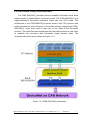
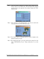
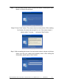
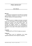
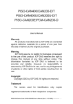
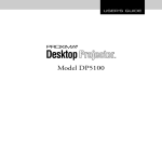
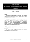
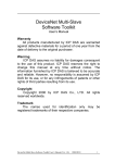
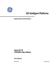
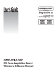
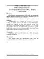
PISO-DNS100-D/T PISO-DNS100U-D/T DeviceNet Multi-Slave PCI Board User’s Manual Warranty All products manufactured by ICP DAS are warranted against defective materials for a period of one year from the date of delivery to the original purchaser. Warning ICP DAS assumes no liability for damages consequent to the use of this product. ICP DAS reserves the right to change this manual at any time without notice. The information furnished by ICP DAS is believed to be accurate and reliable. However, no responsibility is assumed by ICP DAS for its use, or for any infringements of patents or other rights of third parties resulting from its use. Copyright Copyright 2010 by ICP DAS Co., LTD. All rights reserved worldwide. Trademark The names used for identification only may be registered trademarks of their respective companies. PISO-DNS100(U) DeviceNet Slave API functions User’s Manual (Ver: 1.1) 2010/01/07 1 Contents 1. GENERAL INFORMATION .................................................................................4 1.1 DEVICENET INTRODUCTION .......................................................................................4 1.2 DEVICENET APPLICATIONS .........................................................................................6 1.3 PISO-DNS100 ARCHITECTURE ..................................................................................7 1.4 DEVICENET MULTI-SLAVE CHARACTERISTICS .............................................................8 1.5 PISO-DNS100 FIRMWARE CHARACTERISTICS ..........................................................11 1.6 FEATURES ................................................................................................................13 1.7 SPECIFICATIONS .......................................................................................................14 1.8 BLOCK DIAGRAM......................................................................................................15 1.9 PRODUCT CHECK LIST .............................................................................................16 2. HARDWARE CONFIGURATION .....................................................................17 2.1 BOARD LAYOUT ........................................................................................................17 2.2 JUMPER SELECTION .................................................................................................18 2.3 CONNECTOR PIN ASSIGNMENT ..................................................................................20 2.3.1 5-pin screw terminal connector ....................................................................20 2.3.2 9-pin D-sub male connector .........................................................................21 2.3.3 Wire connection ..............................................................................................22 2.4 INDICATOR LED.......................................................................................................23 2.5 HARDWARE INSTALLATION ........................................................................................24 3. DRIVER INSTALLATION OF THE PISO-DNS100 ........................................25 4. FLOW DIAGRAM AND SOFTWARE APPLICATION..................................31 4.1 SOFTWARE ARCHITECTURE .......................................................................................31 4.2 FLOW DIAGRAM FOR SLAVE CONFIGURATION ...........................................................32 4.3 FLOW DIAGRAM FOR SLAVE I/O OPERATION .............................................................33 5. FUNCTION DESCRIPTION ...............................................................................34 5.1 DLL FUNCTION DEFINITION AND DESCRIPTION ........................................................35 5.2 FUNCTION RETURN CODE ........................................................................................37 5.3 FUNCTION DESCRIPTION ..........................................................................................39 5.3.1 DNS100_GetBoardInf ..................................................................................39 5.3.2 DNS100_TotalDNM100Board.....................................................................40 5.3.3 DNS100_ActiveBoard..................................................................................41 5.3.4 DNS100_CloseBoard ...................................................................................42 5.3.5 DNS100_GetDLLVersion ............................................................................43 PISO-DNS100(U) DeviceNet Slave API functions User’s Manual (Ver: 1.1) 2010/01/07 2 5.3.6 DNS100_GetFirmwareVersion ....................................................................44 5.3.7 DNS100_ResetFirmware..............................................................................45 5.3.8 DNS100_GetBaudRate.................................................................................46 5.3.9 DNS100_SetBaudRate .................................................................................47 5.3.10 DNS100_GetSlaveStatus............................................................................48 5.3.11 DNS100_AddDevice ..................................................................................49 5.3.12 DNS100_RemoveDevice............................................................................50 5.3.13 DNS100_AddIOConnection.......................................................................51 5.3.14 DNS100_RemoveIOConnection ................................................................52 5.3.15 DNS100_ReadIOInputData........................................................................53 5.3.16 DNS100_WriteIOInputData .......................................................................54 5.3.17 DNS100_ReadIOOutputData .....................................................................55 5.3.18 DNS100_ClearAllConfig ...........................................................................56 5.3.19 DNS100_ExportEEPROM .........................................................................57 5.3.20 DNS100_ImportEEPROM .........................................................................58 6. DEMO PROGRAMS FOR WINDOWS.................................................................59 6.1 6.2 6.3 6.4 A BRIEF INTRODUCTION TO THE DEMO PROGRAMS ...................................................59 WIRE CONNECTION OF THE CAN BUS......................................................................60 BCB 6 DEMO INTRODUCTION .................................................................................61 VC++ 6 DEMO INTRODUCTION ..............................................................................66 PISO-DNS100(U) DeviceNet Slave API functions User’s Manual (Ver: 1.1) 2010/01/07 3 1. General Information 1.1 DeviceNet Introduction The CAN (Controller Area Network) is a serial communication protocol, which efficiently supports distributed real-time control with a very high level of security. It is an especially suited for networking "intelligent" devices as well as sensors and actuators within a system or sub-system. In CAN networks, there is no addressing of subscribers or stations in the conventional sense, but instead, prioritized messages are transmitted. DeviceNet is one kind of the network protocols based on the CAN bus and mainly used for machine control network, such as textile machinery, printing machines, injection molding machinery, or packaging machines, etc. DeviceNet is a low level network that provides connections between simple industrial devices (sensors, actuators) and higher-level devices (controllers), as shown in Figure 1.1.1 Figure 1.1.1 Example of the DeviceNet network PISO-DNS100(U) DeviceNet Slave API functions User’s Manual (Ver: 1.1) 2010/01/07 4 DeviceNet is a cost effective solution to one kind application of control area network. It reduces the connection wires between devices and provides rapid troubleshooting rejection function. The transfer rate can be up to 500Kbps within 100 meters. The transfer distance can be up to 500 meters in 125Kbps (See Table 1.1). It allows direct peer to peer data exchange between nodes in an organized and, if necessary, deterministic manner. Master/Slave connection model can be supported in the same network. Therefore, DeviceNet is able to facilitate all application communications based on a redefine a connection scheme. However, DeviceNet connection object strands as the communication path between multiple endpoints, which are application objects that is needed to share data. Baud rate (bit/s) Max. Bus length (m) 500 K 100 250 K 250 125 K 500 Table 1.1 The Baud rate and the Bus length PISO-DNS100(U) can represent an economic solution of DeviceNet application and be a DeviceNet multi-slave station. The PISO-DNS100(U) can be used to emulate up to 10 virtual slave devices and acts as Group 2 only Server on the DeviceNet network. It supports up to 512 bytes of input & 512 bytes of output data. Each MAC ID can be set by program and would save into the EEPROM inside the board. The PCI board also has an optically isolated CAN interface. If you want to develop your own Windows applications, it is made to use any development language (VB,VC,BCB...) easily. This offers a standardized API (DLL) with simple functions for card initialization and process data exchange. PISO-DNS100(U) has an independent CAN bus communication port with the ability to cover a wide range of DeviceNet applications. Besides, PISODNS100(U) uses the new CAN controller Phillips SJA1000T and transceiver 82C250, which provide bus arbitration, error detection with auto correction and re-transmission function. It can be installed on almost any windows-based system, for example Win2000/WinXP. It is popularly applied in the industrial automation, building automation, vehicle, marine, and embedded control network. Therefore, that is an easy way to develop the DeviceNet virtual slave station with PISO-DNS100(U). PISO-DNS100(U) DeviceNet Slave API functions User’s Manual (Ver: 1.1) 2010/01/07 5 1.2 DeviceNet Applications DeviceNet is the standardized network application layer optimized for factory automation. It is mainly used in low- and mid-volume automation systems. Some users have also implemented DeviceNet for machine control systems. The main DeviceNet application fields include the following application area (For more information, please refer to www.odva.org): ● Production cell builds and tests CPUs ● Dinnerware production ● Beer brewery ● HVAC module production ● Equipment for food packing ● Textile machines ● Fiberglass twist machine ● Trawler automation system ● Sponge production plant ● LCD manufacturing plant ● Isolation wall manufacturing ● Rolling steel door production ● Overhead storage bin production ● Bottling line ● Pocket-bread bakery ● Tight manufacturing PISO-DNS100(U) DeviceNet Slave API functions User’s Manual (Ver: 1.1) 2010/01/07 6 1.3 PISO-DNS100(U) Architecture The PISO-DNS100(U) provides users to establish DeviceNet virtual slave station rapidly by Master/Slave connection model. The PISO-DNS100(U) is a high-performance DeviceNet multi-slave board with one CPU inside. This architecture of the PISO-DNS100(U) almost doesn’t cost CPU resource and really increases the work efficiency on DeviceNet network. Applying the PISODNS100(U), users don’t need to take care of the detail of the DeviceNet protocol. The inside firmware implements the DeviceNet protocol to help users to establish the connection with DeviceNet master devices easily. The illustration about the idea is shown as Figure 1.3.1. Figure 1.3.1 PISO-DNS100(U) illustration. PISO-DNS100(U) DeviceNet Slave API functions User’s Manual (Ver: 1.1) 2010/01/07 7 1.4 DeviceNet Multi-Slave Characteristics Using the API functions, users don’t need to take care of the detail of the DeviceNet protocol. It can reduce the complexity of user’s DeviceNet virtual slave station Software. The firmware mainly supports the Predefined MasterSlave Connection Set functions to allow users to merge your own data into the DeviceNet network. It can help users to establish the connection with DeviceNet master devices easily. The general application architecture is demonstrated as Figure 1.4.1. Figure 1.4.1 Application architecture PISO-DNS100(U) DeviceNet Slave API functions User’s Manual (Ver: 1.1) 2010/01/07 8 The DeviceNet protocol firmware provides the DeviceNet Slave mechanism by the Predefined Master/Slave Connection Set. The virtual slave would always wait for the request command from the master. The DeviceNet communication protocol can be clarify as two forms: One is the Explicit Message and others are I/O Messages. Here, we only provide one explicit message connection and four I/O connections as depicted in Figure 1.4.2. Figure 1.4.2 DeviceNet Messaging The DeviceNet Communication Protocol is based on the concept of connections method. Master would create connections with slave devices based on the command of exchanging information and I/O data. The slave should provide at least one I/O connection to establish the communication with the master. There are four main steps to create a new virtual slave device in the PISO-DNS100(U). Figure 1.4.3 demonstrates the main process for creating the DeviceNet virtual slave below. Figure 1.4.3 Four steps to establish the DeviceNet connection PISO-DNS100(U) DeviceNet Slave API functions User’s Manual (Ver: 1.1) 2010/01/07 9 1. Add device into EEPROM You should provide the virtual slave device’s MAC ID to add into EEPROM by using API functions. 2. Add IO connection You can choice the virtual slave device’s I/O connection type and the I/O data length by user’s project. When adding the I/O connection, you should provide these parameters. 3. Reset Firmware After adding connections or devices, users should reset the firmware by using API function to make the new setting enable. Then the PISODNS100(U) would wait for the request command form the remote master device. 4. Access I/O data After establishing communication with the master, you can access the I/O data with corresponding read/write function to communicate with the remote master. After adding the device into the EEPROM and reset the firmware, the virtual slaves would send the “Duplicate MAC ID Check Message” immediately to find out the duplicate MAC ID. If there is no duplicate MAC ID, the virtual slave would wait for the request command from the master. Once I/O connections have been created and started, I/O data would be exchanged among master and virtual slaves in the DeviceNet network. Therefore, the master device can access I/O data of the virtual slave devices by one of the four I/O connection methods. The API functions are not only easy to use but also providing a lot of the DeviceNet slave functions to retrieve and deliver the I/O data from the master. For more information, please refer to functions description and demo programs in chapter 5 and 6. PISO-DNS100(U) DeviceNet Slave API functions User’s Manual (Ver: 1.1) 2010/01/07 10 1.5 PISO-DNS100(U) Firmware Characteristics The PISO-DNS100(U) is a high-performance DeviceNet multi-slave board. The firmware inside the board implements DeviceNet slave protocol automatically when the board is active. The firmware always listens to the bus and receives the message at the same time. It works as shown in Figure 1.5.1. Figure 1.5.1 Message Router PISO-DNS100(U) DeviceNet Slave API functions User’s Manual (Ver: 1.1) 2010/01/07 11 The PISO-DNS100(U) firmware has a “ScanList” to store the virtual slave devices information. After power off, the information still exists in the EEPROM. When the users turn on the PC next time, the “ScanList” would be loaded from the EEPROM. The users can easily use the DLL functions to configure it, including adding devices or removing devices. It works as shown in Figure 1.5.2. There is more information about the library functions in chapter 5. Figure 1.5.2 ScanList data structure PISO-DNS100(U) DeviceNet Slave API functions User’s Manual (Ver: 1.1) 2010/01/07 12 1.6 Features Hardware Features z PISO-DNS100 * 33MHz 32bit 5V PCI bus (V2.1) plug and play technology z PISO-DNS100U * Universal PCI supports both 5V and 3.3V PCI bus z Driver support for Windows 2000/XP. z 186 compatible CPU with DeviceNet firmware inside. z 8K bytes DPRAM inside. z One CAN communication port. z Compatible with CAN specification 2.0 parts A and B. z Jumper select 120Ω terminator resistor for each port. z 2 indicating LED (one for green and another for red). z Direct memory mapping to the CAN controllers. z 2500Vrms photo-isolation protection on CAN bus. DeviceNet Firmware Features z Programmable Virtual slave MAC ID. z Programmable transfer-rate 125K, 250K, 500K. z Each port support maximum nodes up to 10 z Support Group 2 Only Server functions z Not support UCMM functions z The maximum Fragment number is (Input/Output) up to 64 z Support I/O Operation Mode: Poll, Bit-Strobe and Change Of State/Cyclic PISO-DNS100(U) DeviceNet Slave API functions User’s Manual (Ver: 1.1) 2010/01/07 13 1.7 Specifications z CAN controller: Phillips SJA1000T. z CAN transceiver: Phillips 82C250. z Signal support: CAN_H, CAN_L. z CAN controller frequency :16 MHz z Connector: 5-pin screw terminal connector or 9-pin D-sub female connector. z Isolation voltage: 2500Vrms on CAN bus. z 186 compactable CPU z 8K bytes DPRAM (1K bytes for system) z 512 K bytes Flash memory (128K bytes for system) z 512K bytes SRAM z RTC (real time clock) inside z 2K EEPROM (256 bytes for system) z 31 bytes NVRAM z Power requirements: 300 mA @ 5V z Environmental: Operating temp: -25~75℃ Storage temp: -40~80℃ Humidity: 5~95% non-condensing Dimensions: 127mm X 121mm PISO-DNS100(U) DeviceNet Slave API functions User’s Manual (Ver: 1.1) 2010/01/07 14 1.8 Block Diagram The figure 1.8.1 shows the block diagram of the PISO-DNS100(U) board. 1. DPRAM (Dual Port RAM) : The DPRAM is the memory buffer which provides the communication channel between PC and PISO-DNS100(U). 2. EEPROM : The EEPROM stores the configuration information. After restarting the PISO-DNS100(U), the configuration data would be loaded form the EEPROM automatically. 3. Control CPU : The CPU inside implementing the DeviceNet slave firmware. 4. CAN Controller : The CAN controller is used for sending and receiving the CAN messages. There is photo isolation between CAN controller and CAN bus. Figure 1.8.1 Block diagram of the PISO-DNS100(U) PISO-DNS100(U) DeviceNet Slave API functions User’s Manual (Ver: 1.1) 2010/01/07 15 1.9 Product Check List In addition to this manual, the package includes the following items: PISO-DNS100(U) card; Software CD ROM; Release Note It is recommended that users should read the release note first. All of the important information needed would be provided in the release note as follows: Where you can find the software driver, utility and demo programs. How to install software & utility. Where is the diagnostic program? FAQ’s and answers. Attention ! If any of these items are missing or damaged, please contact your local field agent. Keep aside the shipping materials and carton in case you want to ship or store the product in the future. PISO-DNS100(U) DeviceNet Slave API functions User’s Manual (Ver: 1.1) 2010/01/07 16 2. Hardware Configuration This section would describe the hardware settings of the PISODNS100(U). This information includes the wire connection and terminal resistance configuration for the CAN network. 2.1 Board Layout Figure 2.1.1 Figure 2.1.2 PISO-DNS100 Board LAYOUT PISO-DNS100U Board LAYOUT Note: PISO-DNS100(U)-T layout is similar with PISO-DNS100(U)-D. The only difference is the position of CAN port connector. The positions of jumper or DIP switch are the same. Therefore, users can also refer to the PISODNS100(U)-D layout to configure the jumper or DIP switch if they use PISODNS100(U)-T. PISO-DNS100(U) DeviceNet Slave API functions User’s Manual (Ver: 1.1) 2010/01/07 17 2.2 Jumper Selection The following table shows the definition of jumpers or DIP switch. Users need to refer to this table to configure the PISO-DNS100- D/T hardware. PISO-DNS100 : Jumper JP1 JP3 JP4 Description Status CAN Port 120Ω terminal resistance. Reset pin for download error. If users want to update firmware but the process is failed, users can enable this jumper to reset the PISO-DNS100-D/T into download mode. Enable Disable Enable Disable None. None DIP switch is used to set the PISODNS100 board No. Switch1 is for bit0, switch2 is for bit1 and so forth. For example, if the left-hand-side switch (switch 1) is ON, the board No. is set to DIP switch 1. The range of board No. is from 0 to This situation indicates 15. Be careful that the board No. for the board No. 1. each PISO-CM100-D/T, PISO-DNS100D/T and PISO-CPM100-D/T must be unique. Table 2.1 Jumper or DIP switch selections PISO-DNS100(U) DeviceNet Slave API functions User’s Manual (Ver: 1.1) 2010/01/07 18 PISO-DNS100U : Jumper JP1 JP2 JP3 SW2 JP4 Description None. Status None. Reset button for download error. If users want to update firmware but the process is fail, users can click this button to reset the PISO-DNS100(U) into download mode. CAN Port 120Ω terminal resistance. DIP switch is used to set the PISODNS100(U) board No. Switch1 is for bit0, switch2 is for bit1 and so forth. For example, if the left-hand-side switch (switch 1) is ON, the board No. is set to 1. The range of board No. is from 0 to 15. Be careful that the board No. for DIP switch each board * PISO-CM100-D/T, This situation indicates * PISO-CM100U-D/T, the board No. 1. * PISO-DNS100-D/T, * PISO-DNS100U-D/T * PISO-CPM100-D/T * PISO-CPM100-D/T must be unique. Table 2.2 Jumper or DIP switch selections for PISO-DNS100U PISO-DNS100(U) DeviceNet Slave API functions User’s Manual (Ver: 1.1) 2010/01/07 19 2.3 Connector Pin Assignment The PISO-DNS100(U)-T is equipped with one 5-pin screw terminal connector and the PISO-DNS100(U)-D is equipped with one 9-pin D-sub male connector for wire connection of the CAN bus. The connector’s pin assignment is specified as follows: 2.3.1 5-pin screw terminal connector The 5-pin screw terminal connector for the CAN bus is shown in Figure 2.3.1 and the details for the pin assignment are presented in Table 2.2. 1 2 3 4 5 CAN-L Shield CAN-H Figure2.3.1 Pin No. 5-pin screw terminal connector Signal Description 1 N/A No use 2 CAN_H CAN_H bus line (dominant high) 3 CAN_SHLD Optional CAN Shield 4 CAN_L CAN_L bus line (dominant low) 5 N/A No use Table 2.2: Pin assignment of 5-pin screw terminal connector PISO-DNS100(U) DeviceNet Slave API functions User’s Manual (Ver: 1.1) 2010/01/07 20 2.3.2 9-pin D-sub male connector The 9-pin D-sub male connector of the CAN bus interface is shown in Figure 2.3.2 and the corresponding pin assignments are given in Table 2.3. CAN-L 1 2 6 Shield 3 4 5 7 8 9 CAN-H Figure 2.3.2 Pin No. 9-pin D-sub male connector Signal Description 1 N/A No use 2 CAN_L CAN_L bus line (dominant low) 3 N/A No use 4 N/A No use 5 CAN_SHLD Optional CAN Shield 6 N/A No use 7 CAN_H CAN_H bus line (dominant high) 8 N/A No use 9 N/A No use Table 2.3 Pin assignment of the 9-pin D-sub male connector PISO-DNS100(U) DeviceNet Slave API functions User’s Manual (Ver: 1.1) 2010/01/07 21 2.3.3 Wire connection In order to minimize the reflection effects on the CAN bus line, the CAN bus line has to be terminated at both ends by two terminal resistances as in the following figure. According to the ISO 11898-2 spec, each terminal resistance is 120Ω (or between 108Ω~132Ω). The length related resistance should have 70 mΩ/m. Users should check the resistances of the CAN bus, before they install a new CAN network. Device 1 Device 2 ... Device N 120Ω 120Ω CAN_H CAN_L Figure 2.3.3 CAN bus network topology Moreover, to minimize the voltage drop over long distances, the terminal resistance should be higher than the value defined in the ISO 11898-2. The following table can be used as a good reference. Bus Cable Parameters Terminal Resistance (Ω) Bus Length (meter) Length Related Resistance (mΩ/m) 0~40 70 0.25(23AWG)~ 0.34mm2(22AWG) 124 (0.1%) 40~300 < 60 0.34(22AWG)~ 0.6mm2(20AWG) 127 (0.1%) 300~600 < 40 0.5~0.6mm2 (20AWG) 150~300 600~1K < 20 0.75~0.8mm2 (18AWG) 150~300 Table 2.4 Cross Section (Type) Relationship between cable characteristics and terminal resistance PISO-DNS100(U) DeviceNet Slave API functions User’s Manual (Ver: 1.1) 2010/01/07 22 2.4 Indicator LED Green LED 1 2 3 4 5 OFF OFF ON ON Twinkle Red LED ON Twinkle Event or Status There are some problems with the hardware of the PISO-DNS100(U) board. Please contact your local field agent. There are some virtual slaves which can not be on-line. There exists at least one duplicate MAC ID in the DeviceNet network. OFF This indicates that the firmware is working. All virtual slave devices in the PISO-DNS100(U) are communicating with the master successfully. ON This indicates that the firmware works fine. But there is no any virtual slave device configuration inside the EEPROM of the PISODNS100(U). OFF 1. There are virtual slaves which have problems with the communication. 2. The slaves are on-line and waiting for the request message from the master. PISO-DNS100(U) DeviceNet Slave API functions User’s Manual (Ver: 1.1) 2010/01/07 23 2.5 Hardware Installation When users want to use the PISO-DNS100(U)-D/T board, the hardware installation needs to be finished as following steps. 1. Shutdown your personal computer. 2. Configure the DIP switch and JP1 of your PISO-DNS100(U)-D/T for board No. and terminal resistance. More detail information could be found on the figure 2.1 and table 2.1. 3. Check JP3 status of PISO-DNS100(U)-D/T. If necessary, enable it. 4. Find an empty PCI slot for your PISO-DNS100(U)-D/T on the mother board of the personal computer. Plug the configured PISO-DNS100(U)-D/T into this empty PCI slot. See figure 2.5.1. 5. Plug your CAN bus cable(s) into the 5-pin screw terminal connector or the 9pin D-sub connector. When the steps described above is completed, turn on the personal computer. Figure 2.5.1 PISO-DNS100(U) installation PISO-DNS100(U) DeviceNet Slave API functions User’s Manual (Ver: 1.1) 2010/01/07 24 3. Driver Installation of the PISO-DNS100(U) The software Installation for DeviceNet application is demonstrated as the following descriptions. After finishing the procedure, the driver, demos, manual and Utility can be in your PC. For the advanced application, users can refer to the basic demo programs to develop the customized DeviceNet master application. The driver of PISO-DNS100(U) can be used in 2000/XP Windows environments. For these Windows operation systems, the recommended installation procedure is given as follows: Step 1: Insert the companion CD into the CD-ROM driver and wait a few seconds until the installation program starts automatically. If it cannot be started automatically for some reason, please doubleclick the file ICPDAS.EXE on this CD. The screenshot likes the following picture. Please click “CAN Series” item. Step 2: After changing to the following picture, please click the “DeviceNet” item. PISO-DNS100(U) DeviceNet Slave API functions User’s Manual (Ver: 1.1) 2010/01/07 25 Step 3: When the window is changing to the picture below, please move the mouse cursor on the “Slave” item. The DeviceNet slave products would be shown in the right side of the window. Please click “PISODNS100” item. Step 4: After changing to the following picture, the users can read more information about the PISO-DNS100(U) board. Step 5: Click “install Toolkit” for Windows 2000, XP, which is based on the operation system you used”. Step 6: After finishing the step 5, the users would see the setup file in the folder “PISO-DNS100_V12.exe”. Please double-click it to run the setup. PISO-DNS100(U) DeviceNet Slave API functions User’s Manual (Ver: 1.1) 2010/01/07 26 Step 7: This first setup screen shoot is shown as follows. Please press “Next” button to continue the process. Step 8: Press “Next” button. The screen shoot is shown below. After reading the license, the users can accept it or not. If the users accept it, please select “I accept….” and press “Next” button. Step 9: After accepting the license, the next screen shoot is shown as follows. Users can edit your name and company name. After editing the information, please press “Next” button. PISO-DNS100(U) DeviceNet Slave API functions User’s Manual (Ver: 1.1) 2010/01/07 27 Step 10: After editing the information, the next screen shoot is shown as follows. Please select “Complete” item and press “Next” button. Step 11: The next screen shoot is shown as follows. Please press “Install” button. The setup process would start. Step 12: The setup process is running. The screen shoot is shown below. PISO-DNS100(U) DeviceNet Slave API functions User’s Manual (Ver: 1.1) 2010/01/07 28 Step 13: Wait for the setup process finishing. The next screen shoot is shown below. After finishing the process, please press “Finish” button. Step 14: The next screen shoot is shown as follows. Please restart your PC. Then the setup software would copy the related material to the indicated directory and register the driver on your computer. The driver target directory is different according to the different systems as follows. Windows NT/2000 – WINNT\SYSTEM32\DRIVERS Windows 98/Me/XP – WINDOWS\SYSTEM32\DRIVERS The other data and resource is copied to the following directory: C:\ICPDAS\PISO-DNS100\ PISO-DNS100(U) DeviceNet Slave API functions User’s Manual (Ver: 1.1) 2010/01/07 29 The program files picture is shown as follow. Note:DeviceNet Multi-Slave Utility is a useful tool for users to configure the DeviceNet virtual slave devices. You can refer to DeviceNet Virtual slave Utility manual to know the detail. The next sections in this manual explain how to implement the DeviceNet virtual slave station by API functions. PISO-DNS100(U) DeviceNet Slave API functions User’s Manual (Ver: 1.1) 2010/01/07 30 4. Flow Diagram and Software Application 4.1 Software architecture The DeviceNet DLL driver (DNS100.dll) collection of function calls for the PISO-DNS100(U) cards used in Windows 2000/XP systems. The application structure is presented in the following figure. The user’s DeviceNet application programs can be developed by the following designated tools: VC, VB, Delphi and Borland C++ Builder…etc. In these tools, the application program can call the DNS100.DLL driver to implement DeviceNet network application. And then the DeviceNet DLL driver would throughout the CM100.dll into the KP_CM100.sys and windrvr6.sys to access the hardware system, as shown in the following Figure 4.1.1. Figure 4.1.1 Software architecture in the Windows system In the following sub-section, we show some flow diagrams to describe how to apply the DeviceNet protocol (DNS100.DLL) to build a virtual slave device. Section 4.2 and 4.3 show the flow diagram for users to understand easily. Note that users need to follow the operation principle of the DeviceNet protocol correctly and easily to communicate with the remote master by these connection methods. PISO-DNS100(U) DeviceNet Slave API functions User’s Manual (Ver: 1.1) 2010/01/07 31 4.2 Flow Diagram for Slave Configuration After deciding the DeviceNet I/O size and connection type of the virtual slave devices, users should save the parameters into the EEPROM in PISODNS100(U). The EEPROM would store the configuration data. The firmware in PISO-DNS100(U) would load the previous configuration from the EEPROM in the next boot-up. After setting the configuration data, the users should reset the firmware in the PISO-DNS100(U) to make new configuration active. The configuration diagram is shown in Figure 4.2.1. There is more information about those functions in the next chapter. Figure 4.2.1 Slave Configuration Diagram PISO-DNS100(U) DeviceNet Slave API functions User’s Manual (Ver: 1.1) 2010/01/07 32 4.3 Flow Diagram for Slave I/O Operation After configuring the PISO-DNS100(U), the users can easily read or write I/O data from or to the remote DeviceNet master device. The users don't need to know about the DeviceNet protocol. The main steps are shown in Figure 4.3.1 Figure 4.3.1 Virtual slave I/O Operation Diagram PISO-DNS100(U) DeviceNet Slave API functions User’s Manual (Ver: 1.1) 2010/01/07 33 5. Function description All the functions of the PISO-DNS100(U) can be separated into four groups. The idea is shown Figure 5.1.1. There is more detail description in chapter 5.3. Figure 5.1.1 Four Function Groups [Board Functions] These functions in this group help users to find DNS100(U) boards or get board’s information. The users can use these functions to configure or manage the boards in the PC. [Firmware Functions] These functions in this group help users to operate the firmware or get the status of the firmware inside the PISO-DNS100(U). [Operating Functions] These operating functions provide the users to configure the virtual slave configurations. These include adding and removing virtual slave devices. They help users to manage the configurations inside the EEPROM. [I/O Functions] These functions help user to read or write the I/O data from or to the remote master devices. PISO-DNS100(U) DeviceNet Slave API functions User’s Manual (Ver: 1.1) 2010/01/07 34 5.1 DLL Function Definition and Description All the functions provided in the DNS100.dll are listed in the following table and detail information for every function is presented in the next sub-section. However, in order to make the descriptions more simply and clear, the attributes for the both the input and output parameter functions are given as [input] and [output] respectively, as shown in following table. Keyword Set parameter by user before Get the data from this parameter calling this function? after calling this function? [ input ] Yes No [ output ] No Yes Table 5.1.1 Functions Table (Board Functions) No. Function Name Description 1 DNS100_GetBoardInf Get the information of the PISO-DNS100(U) 2 DNS100_TotalDNS100Board Get total PISO-DNS100(U) boards in the PC 3 DNS100_ActiveBoard Make PISO-DNS100(U) active 4 DNS100_CloseBoard Close the PISO-DNS100(U) driver 5 DNS100_GetDLLVersion Get the DLL version of the DNS100.DLL Table 5.1.2 Functions Table (Firmware Functions) No. Function Name Description 1 DNS100_GetFirmwareVersion Get the version of the firmware inside the PISO-DNS100(U) 2 DNS100_ResetFirmware Reset the firmware in the PISO-DNS100(U) PISO-DNS100(U) DeviceNet Slave API functions User’s Manual (Ver: 1.1) 2010/01/07 35 Table 5.1.3 Functions Table (Operating Functions) No. Function Name Description 1 DNS100_GetBaudRate Get the baud rate of the CAN bus 2 DNS100_SetBaudRate Set the baud rate of the CAN bus 3 DNS100_AddDevice Add the specific virtual slave device’s information into the PISO-DNS100(U) 4 DNS100_RemoveDevice Remove the specific virtual slave device’s information from the PISO-DNS100(U) 5 DNS100_AddIOConnection Add specific virtual slave device’s I/O information into the PISO-DNM100(U) 6 DNS100_RemoveIOConnection Remove specific virtual slave device’s I/O information from the PISO-DNS100(U) 7 DNS100_ClearAllConfig Clear all configuration in PISO-DNS100(U) 8 DNS100_ExportEEPROM Export all DNS100(U) 9 DNS100_ImportEEPROM Import new DNS100(U) configuration configuration from PISO- into PISO- Table 5.1.4 Functions Table (I/O Functions) No. Function Name Description 1 DNS100_ReadIOInputData Read specific virtual slave device’s input data 2 DNS100_WriteIOInputData Write specific virtual slave device’s input data 3 DNS100_ReadIOOutputData Read specific virtual slave device’s output data 4 DNS100_GetSlaveStatus Get the status of the virtual slave in the PISO-DNS100(U) at present PISO-DNS100(U) DeviceNet Slave API functions User’s Manual (Ver: 1.1) 2010/01/07 36 5.2 Function Return Code Table 5.2.1 Interpretation of the return code (Hardware Error) 1/1 Return Code 0 Error ID DNS100_NoError Comment No error 10001 DNS100_DriverError Kernel driver is not opened. 10002 DNS100_ActiveBoardError This board can not be activated. 10003 DNS100_BoardNumberError 10004 DNS100_PortNumberError The Board number exceeds the total board numbers. The Port number is not correct. 10007 DNS100_InitError The PISO-DNS100(U) replies error. 10021 DNS100_SoftBufferIsEmpty No CAN messages in the buffer. 10022 DNS100_SoftBufferIsFull The software buffer is overflow. 10023 DNS100_TimeOut The PISO-DNS100(U) has no response. 10024 DNS100_SetCyclicMsgFailure The cyclic messages are over 5 counts. This is special function for CAN. The command length is over 512 bytes. 10025 DNS100_DpramOverRange 10026 DNS100_NoDpramCmd There is no command in DPRAM. 10027 DNS100_ModeError This board can’t be changed to firmware mode. There is no firmware in PISODNS100(U). The download firmware process is 10030 DNS100_NoFileInside 10031 DNS100_DownloadFailure failure. 10032 DNS100_EEPROMDamage The EEPROM is out of order. 10033 DNS100_NotEnoughSpace 10034 DNS100_StillDownloading The firmware is too large to put it into the PISO-DNS100(U)-D/T The firmware is downloading. 10035 DNS100_BoardModeError The firmware mode is error. 10036 DNS100_CardTypeError The firmware is not for the PISODNS100(U) PISO-DNS100(U) DeviceNet Slave API functions User’s Manual (Ver: 1.1) 2010/01/07 37 Table 5.2.2 Interpretation of the return code (DeviceNet Error) Return Code DeviceNet Error Comment DNSXS_MACIDError The MAC ID number exceeds the range from 0 to 63. 1001 DNSXS_SlaveStandby The virtual slave device is on-line now. It is waiting for the master request. 1002 DNSXS_BaudRateError The baud rate number exceeds the range from 0 to 2. 1003 DNSXS_ExceedMaxDevice The EEPROM is full. The users can not add virtual slave devices any more. 1004 DNSXS_ConnectionTypeError The connection type number exceeds the range from 1 to 4. 1005 DNSXS_BoardNotActive The board doesn’t be activated. 1006 DNSXS_SlaveError The virtual slave device has some errors. 1101 DNSXS_DeviceAlreadyExist The virtual slave device already exists in the EEPROM. 1102 DNSXS_DeviceNotExist The virtual slave device doesn’t exist in the EEPROM. 1104 DNSXS_ScanListEmpty The EEPROM doesn’t include any configuration. 1107 The virtual slave doesn’t DNSXS_ConnectionNotAllocate communicate with the master device. 1000 1201 DNSXS_DataLengthError The input length of buffer doesn’t match with the length of the virtual slave. 1400 DNSXS_ReadEEPROMError The EEPROM is out of order. 1401 DNSXS_WriteEEPROMError The EEPROM is out of order. PISO-DNS100(U) DeviceNet Slave API functions User’s Manual (Ver: 1.1) 2010/01/07 38 5.3 Function Description 5.3.1 z DNS100_GetBoardInf Description: This function is used to obtain the driver information of PISODNS100(U) board. z Syntax: DWORD DNS100_GetBoardInf (BYTE BoardNo, DWORD *dwVID, DWORD *dwDID, DWORD *dwSVID, DWORD *dwSDID, DWORD *dwSAuxID, DWORD *dwIrqNo) z Parameter: BoardNo: [input] PISO-DNS100(U) board number (0~15) dwVID: [output] The address of a variable which is used to receive the vendor ID. dwDID: [output] The address of a variable used to receive device ID. dwSVID: [output] The address of a variable applied to receive sub-vendor ID. dwSDID: [output] The address of a variable applied to receive sub-device ID. dwSAuxID: [output] The address of a variable used to receive sub-auxiliary ID. dwIrqNo: [output] The address of a variable used to receive logical interrupt number. z Return: Please refer to Table 5.2.1. PISO-DNS100(U) DeviceNet Slave API functions User’s Manual (Ver: 1.1) 2010/01/07 39 5.3.2 z DNS100_TotalDNS100Board Description: The function can get the count of total PISO-DNS100(U) boards in the user’s PC. z Syntax: DWORD DNS100_TotalDNS100Board (BYTE *TotalBoards, BYTE *BoardIDList) z Parameter: TotalBoards: [output] The count of total board. BoardIDList: [output] The list of all DIP-Switch No. in each board. z Return: Please refer to Table 5.2.1. PISO-DNS100(U) DeviceNet Slave API functions User’s Manual (Ver: 1.1) 2010/01/07 40 5.3.3 z DNS100_ActiveBoard Description: The function is used to activate PISO-DNS100(U)-D/T. It must be called once before using the other functions of PISO-DNS100(U)-D/T APIs. z Syntax: DWORD DNS100_ActiveBoard (BYTE BoardNo) z Parameter: BoardNo: [input] PISO-DNS100(U) board number (0~15) z Return: Please refer to Table 5.2.1. PISO-DNS100(U) DeviceNet Slave API functions User’s Manual (Ver: 1.1) 2010/01/07 41 5.3.4 DNS100_CloseBoard z Description: The function is used to stop, close the kernel driver and release the device resource from computer device resource. This method must be called once before exiting the user’s application program. z Syntax: DWORD DNS100_CloseBoard (BYTE BoardNo) z Parameter: BoardNo: [input] PISO-DNS100(U) board number (0~15) z Return: Please refer to Table 5.2.1. PISO-DNS100(U) DeviceNet Slave API functions User’s Manual (Ver: 1.1) 2010/01/07 42 5.3.5 z DNS100_GetDLLVersion Description: The function can obtain the version information of DNS100.dll driver. z Syntax: DWORD DNS100_GetDLLVersion (void) z Parameter: None z Return: The DLL version information. For example: If 100(Dec) is return, it means driver version is 1.00. z Error Return: Please refer to Table 5.2.1 and Table 5.2.2. PISO-DNS100(U) DeviceNet Slave API functions User’s Manual (Ver: 1.1) 2010/01/07 43 5.3.6 z DNS100_GetFirmwareVersion Description: The function can obtain the version information of the firmware inside the PISO-DNS100(U). z Syntax: DWORD DNS100_GetFirmwareVersion (BYTE BoardNo) z Parameter: BoardNo: [input] PISO-DNS100(U) board number (0~15) z Return: The firmware version information. For example: If 100(Hex) is return, it means firmware version is 1.00. z Error Return: Please refer to Table 5.2.1. PISO-DNS100(U) DeviceNet Slave API functions User’s Manual (Ver: 1.1) 2010/01/07 44 5.3.7 z DNS100_ResetFirmware Description: The function is used to reset the PISO-DNS100(U) firmware. When the users have changed the baud rate of CAN bus or changed the configuration of the virtual slave devices, the function must be called to make the change enable. After calling this function, the users should wait for 1 or 2 seconds to make the firmware boot up completely. z Syntax: DWORD DNS100_ResetFirmware (BYTE BoardNo) z Parameter: BoardNo: [input] PISO-DNS100(U) board number (0~15) z Return: Please refer to Table 5.2.1. PISO-DNS100(U) DeviceNet Slave API functions User’s Manual (Ver: 1.1) 2010/01/07 45 5.3.8 z DNS100_GetBaudRate Description: This function can help you to get the baud rate information of the PISODNS100(U). z Syntax: DWORD DNS100_GetBaudRate (BYTE BoardNo) z Parameter: BoardNo: [input] PISO-DNS100(U) board number (0~15) z Return: The baud rate information in the PISO-DNS100(U). If the value is 0, the baud rate is 125Kbps. If the value is 1, the baud rate is 250Kbps. If the value is 2, the baud rate is 500Kbps. z Error Return: Please refer to Table 5.2.1 and Table 5.2.2. PISO-DNS100(U) DeviceNet Slave API functions User’s Manual (Ver: 1.1) 2010/01/07 46 5.3.9 z DNS100_SetBaudRate Description: This function can set the DeviceNet baud rate of the PISODNS100(U). After calling this function, you must call DNS100_ResetFirmware or DNS100_ActiveBoard to reset the firmware. It would make the changes enabled. z Syntax: DWORD DNS100_SetBaudRate (BYTE BoardNo, BYTE BaudRate) z Parameter: BoardNo: [input] PISO-DNS100(U) board number (0~15) BaudRate: [input] The new baud rate value. 0 : 125K bps 1 : 250K bps 2 : 500K bps z Return: Please refer to Table 5.2.1 and Table 5.2.2. PISO-DNS100(U) DeviceNet Slave API functions User’s Manual (Ver: 1.1) 2010/01/07 47 5.3.10 z DNS100_GetSlaveStatus Description: The function is used to obtain the virtual slave status inside the PISODNS100(U). The users can call this function to make sure that the DeviceNet virtual slave is working successfully. z Syntax: DWORD DNS100_GetSlaveStatus (BYTE BoardNo, BYTE SlaveID) z Parameter: BoardNo: [input] PISO-DNS100(U) board number (0~15) SlaveID: [input] The DeviceNet slave’s MAC ID (0~63) z Return: Please refer to Table 5.2.1 and Table 5.2.2. PISO-DNS100(U) DeviceNet Slave API functions User’s Manual (Ver: 1.1) 2010/01/07 48 5.3.11 z DNS100_AddDevice Description: This function can add the new virtual slave device into the PISODNS100(U) and save the information into the EEPROM. Before communicating with the master device, the users should call this function to add the virtual slave device. z Syntax: DWORD DNS100_AddDevice (BYTE BoardNo, BYTE SlaveID) z Parameter: BoardNo: [input] PISO-DNS100(U) board number (0~15) SlaveID: [input] The DeviceNet virtual slave’s MAC ID (0~63) z Return: Please refer to Table 5.2.1 and Table 5.2.2. PISO-DNS100(U) DeviceNet Slave API functions User’s Manual (Ver: 1.1) 2010/01/07 49 5.3.12 z DNS100_RemoveDevice Description: This function is used for removing the specific virtual slave device from the PISO-DNS100(U). And the corresponding I/O connection configuration would also be erased. At the same time, the information of the device in EEPROM is erased. z Syntax: DWORD DNS100_RemoveDevice (BYTE BoardNo, BYTE SlaveID) z Parameter: BoardNo: [input] PISO-DNS100(U) board number (0~15) SlaveID: [input] The DeviceNet slave’s MAC ID (0~63) z Return: Please refer to Table 5.2.1 and Table 5.2.2. PISO-DNS100(U) DeviceNet Slave API functions User’s Manual (Ver: 1.1) 2010/01/07 50 5.3.13 z DNS100_AddIOConnection Description: This method is used to add the I/O connection (Poll, Bit-Strobe and COS/Cyclic) of the specific virtual slave device. The PISO-DNS100(U) can get/set the data via the connection, which connects to the specific virtual slave, according to the produced / consumed connection path of this virtual slave device. This configuration data would be saved into the EEPROM of the PISO-DNS100(U). z Syntax: DWORD DNS100_AddIOConnection (BYTE BoardNo, BYTE SlaveID, BYTE Type, WORD DeviceInputLen, WORD DeviceOutputLen) z Parameter: BoardNo: [input] PISO-DNS100(U) board number (0~15) SlaveID: [input] The DeviceNet virtual slave’s MAC ID (0~63) Type: [input] The I/O Connection type. (1 ~ 4). 1 : Poll connection. 2 : Bit-Strobe connection. 3 : COS connection. 4 : Cyclic connection. DeviceInputLen: [input] The input data length of the virtual slave device. DeviceOutputLen: [input] The output data length of the virtual slave device. z Return: Please refer to Table 5.2.1 and Table 5.2.2. PISO-DNS100(U) DeviceNet Slave API functions User’s Manual (Ver: 1.1) 2010/01/07 51 5.3.14 z DNS100_RemoveIOConnection Description: The function is used to remove the I/O connection configuration. z Syntax: DWORD DNS100_RemoveIOConnection (BYTE BoardNo, BYTE SlaveID, BYTE Type) z Parameter: BoardNo: [input] PISO-DNS100(U) board number (0~15) SlaveID: [input] The remote virtual slave device’s MAC ID (0~63) Type: [input] The I/O Connection type. (1 ~ 4). 1 : Poll connection. 2 : Bit-Strobe connection. 3 : COS connection. 4 : Cyclic connection. z Return: Please refer to Table 5.2.1 and Table 5.2.2. PISO-DNS100(U) DeviceNet Slave API functions User’s Manual (Ver: 1.1) 2010/01/07 52 5.3.15 z DNS100_ReadIOInputData Description: This function is used to read the input data which would be sent to the master device. z Syntax: DWORD DNS100_ReadIOInputData (BYTE BoardNo, BYTE SlaveID, BYTE Type, BYTE *IOInputData, WORD *InputDataLen) z Parameter: BoardNo: [input] PISO-DNS100(U) board number (0~15) SlaveID: [input] The virtual DeviceNet slave’s MAC ID (0~63) Type: [input] The I/O Connection type. (1 ~ 4). 1 : Poll connection. 2 : Bit-Strobe connection. 3 : COS connection. 4 : Cyclic connection. IOInputData: [output] The input data buffer of the virtual slave device. InputDataLen: [output] The input data length of the virtual slave device. z Return: Please refer to Table 5.2.1 and Table 5.2.2. PISO-DNS100(U) DeviceNet Slave API functions User’s Manual (Ver: 1.1) 2010/01/07 53 5.3.16 z DNS100_WriteIOInputData Description: This function is used to write the input data which would be sent to the master device. The users call this function to update the input data. The corresponding input data buffer of the master device would change synchronously. z Syntax: DWORD DNS100_WriteIOInputData (BYTE BoardNo, BYTE SlaveID, BYTE Type, BYTE *IOInputData, WORD InputDataLen) z Parameter: BoardNo: [input] PISO-DNS100(U) board number (0~15) SlaveID: [input] The virtual DeviceNet slave’s MAC ID (0~63) Type: [input] The I/O Connection type. (1 ~ 4). 1 : Poll connection. 2 : Bit-Strobe connection. 3 : COS connection. 4 : Cyclic connection. IOInputData: [Input] The input data buffer which includes new data. InputDataLen: [Input] The input data length of the virtual slave device. z Return: Please refer to Table 5.2.1 and Table 5.2.2. PISO-DNS100(U) DeviceNet Slave API functions User’s Manual (Ver: 1.1) 2010/01/07 54 5.3.17 z DNS100_ReadIOOutputData Description: This function is used to get the output data from the master device. As soon as the output data of the master device changes, the users can use this function to obtain the changes from master synchronously. z Syntax: DWORD DNS100_ReadIOOutputData (BYTE BoardNo, BYTE SlaveID, BYTE Type, BYTE *IOOutputData, WORD *OutputDataLen) z Parameter: BoardNo: [input] PISO-DNS100(U) board number (0~15) SlaveID: [input] The virtual DeviceNet slave’s MAC ID (0~63) Type: [input] The I/O Connection type. (1 ~ 4). 1 : Poll connection. 2 : Bit-Strobe connection. 3 : COS connection. 4 : Cyclic connection. IOOutputData: [output] The output data which was sent form the master. OutputDataLen: [output] The output data length of the virtual slave device. z Return: Please refer to Table 5.2.1 and Table 5.2.2. PISO-DNS100(U) DeviceNet Slave API functions User’s Manual (Ver: 1.1) 2010/01/07 55 5.3.18 z DNS100_ClearAllConfig Description: This function would clear all configurations in the EEPROM of the PISO-DNS100(U). At the same time, the baud rate would be set to the default value (125K bps). z Syntax: DWORD DNS100_ClearAllConfig (BYTE BoardNo) z Parameter: BoardNo: [input] PISO-DNS100(U) board number (0~15) z Return: Please refer to Table 5.2.1 and Table 5.2.2. PISO-DNS100(U) DeviceNet Slave API functions User’s Manual (Ver: 1.1) 2010/01/07 56 5.3.19 z DNS100_ExportEEPROM Description: This function is used for obtaining all configurations in the EEPROM which is in the PISO-DNS100(U). The user can save these information data with your own data format for importing into the next PISODNS100(U)board. z Syntax: DWORD DNS100_ ExportEEPROM (BYTE BoardNo, WORD *TotalDevices, BYTE *SlaveIDList, BYTE *TypeList, WORD *InputDataLenList, WORD *OutputDataLenList) z Parameter: BoardNo: [input] PISO-DNS100(U) board number (0~15) TotalDevices: [output] The amount of total data SlaveIDList: [output] The buffer of the virtual slave ID TypeList: [output] The buffer of the connection type InputDataLenList: [output] The input data length of all virtual slaves. OutputDataLenList: [output] The output data length of all virtual slaves. z Return: Please refer to Table 5.2.1 and Table 5.2.2. PISO-DNS100(U) DeviceNet Slave API functions User’s Manual (Ver: 1.1) 2010/01/07 57 5.3.20 z DNS100_ImportEEPROM Description: The function is used for importing all configurations into the EEPROM which is in the PISO-DNS100(U). z Syntax: DWORD DNS100_ImportEEPROM (BYTE BoardNo, WORD TotalDevices, BYTE *SlaveIDList, BYTE *TypeList, WORD *InputDataLenList, WORD *OutputDataLenList) z Parameter: BoardNo: [input] PISO-DNS100(U) board number (0~15) TotalDevices: [input] The amount of total data SlaveIDList: [input] The buffer of the virtual slave ID TypeList: [input] The buffer of the connection type InputDataLenList: [input] The input data length of all virtual slaves. OutputDataLenList: [input] The output data length of all virtual slaves. z Return: Please refer to Table 5.2.1 and Table 5.2.2. PISO-DNS100(U) DeviceNet Slave API functions User’s Manual (Ver: 1.1) 2010/01/07 58 6. Demo Programs for Windows All of demo programs would not work normally if PISO-DNS100(U) driver would not be installed correctly. During the installation process of the driver, the install-shields would register the correct kernel driver to the operation system and copy the DLL driver and demo programs to the correct position based on the driver software package you have selected (Win 2000,XP). After completing the driver installation, the related demo programs, development library and declaration header files for different development environments are installed in the system as follows. The PISO-DNS100’s root directory is C:\ICPDAS\PISO-DNS100 |--\DLL The DLL driver for the user’s application |--\Driver The window driver of the PISO-DNS100 |--\Manual The user manual of the PISO-DNS100 |--\Utility The DeviceNet Slave utility |--\Demo Demo program |--\Demo\BCB 6 Demo Demos for Borland C++ Builder 6 |--\Demo\VC++ 6 Demo Demos for Visual C++ 6 |--\Demo\VB 6 Demo Demos for Visual Basic 6 6.1 A brief introduction to the demo programs Demonstrate the basic functions to exchange I/O data with the remote master device. The demo program would lead you step by step to complete the setting and communication. The demo program would show you how to set the input value and how to get the output value. Here the input value means that the value would transmit from the virtual slave to the master device. The output value means that the value would transmit form the master to the virtual slave device. PISO-DNS100(U) DeviceNet Slave API functions User’s Manual (Ver: 1.1) 2010/01/07 59 6.2 Wire Connection of the CAN bus Before starting the demos, the users should have at least one virtual slave device. Here show the users how to connect the master and virtual slave devices by CAN bus. The virtual slave devices should be connected to form the serial type which is shown as Figure 6.2.1 Figure 6.2.1 Correct wire connection The following wire connection is wrong which is shown as Figure 6.2.2 Figure 6.2.2 Wrong wire connection PISO-DNS100(U) DeviceNet Slave API functions User’s Manual (Ver: 1.1) 2010/01/07 60 6.3 BCB 6 Demo Introduction BCB 6 Demo is the example used for starting the DeviceNet I/O data exchange. The screen shoot is shown as Figure 6.3.1. This demo program is designed to create new virtual slave devices step by step. This program would read the output value of the virtual slave device when the POLL connection has been established. Before exercising this demo, the users should have at least one DeviceNet master device with configuration software and finish the wire connection between the Master and virtual slave device. (See Figure 6.2.1) Figure 6.3.1 the screen shoot of VC++ 6 Demo After running the program, the users would see the “TotalBoard” information on the left and top corner of the screen. This function determinates how many PISO-DNS100(U) in your PC automatically. If it doesn’t find any board, the users should check that the windows driver has been installed successfully. Otherwise, if it has found at lease one board, the users can continue exercising the demo program. Step 1 : Select Board ID PISO-DNS100(U) DeviceNet Slave API functions User’s Manual (Ver: 1.1) 2010/01/07 61 The DIP-Switch on the board means the ID of this board. The users should make sure that every board’s ID in your PC is unique. The drop-down list would show the board’s ID which the users have selected. If you have more than one PISO-DNS100(U) boards, please select the correct board ID which you want to use. Step 2 : ActiveBoard Before performing other buttons, the “ActiveBoard” button should be clicked firstly. After clicking the button, the return message would be “OK”. It is shown as Figure 6.3.2. Otherwise, please check the windows driver has been installed successfully. Figure 6.3.2 “ActiveBoard” OK Step 3 : Clear All Config To avoid unknown configuration in the PISO-DNS100(U), the users can push this button to clear all configuration in the board. Note that the baud rate of the CAN bus would be set to 125K bps. Step 4 : Set Baud Rate PISO-DNS100(U) DeviceNet Slave API functions User’s Manual (Ver: 1.1) 2010/01/07 62 The default baud rate is 125Kbps. If the users want to change the value, you can select the correct value from the drop-down list. After changing the baud rate, the uses should reset the firmware in PISO-DNS100(U) by pushing the “ActiveBoard” button again. Wait for 1 or 2 seconds then go to the next step. Step 5 : Add Slave ID 12 and 53 For the convenient, we assumed that we have two virtual slave devices in the network. It is shown as Figure 6.3.3. One ID is 12 with 1 byte length of input and output. The other ID is 53 with 2 bytes length of input and output. When pushing the “Add Device 12” and “Add Device 53” buttons, it would add these two virtual slave devices into the PISO-DNS100(U). After adding these virtual slave devices, the uses should reset the firmware in PISO-DNS100(U) by clicking the “ActiveBoard” button. Wait for 1 or 2 seconds then go to the next step. Figure 6.3.3 “Add Device 12” OK PISO-DNS100(U) DeviceNet Slave API functions User’s Manual (Ver: 1.1) 2010/01/07 63 Step 6 : Wait for the Master Request This step is waiting for the request command form the remote master device. It is shown as Figure 6.3.4. The user should make the master device to communicate with these two devices. If these two virtual slave devices have communicated with the master device successfully, the users can not go to next step until the connection of the virtual slave devices have been established. Figure 6.3.4 Waiting for the Master PISO-DNS100(U) DeviceNet Slave API functions User’s Manual (Ver: 1.1) 2010/01/07 64 Step 7 : Read and Write I/O Data If the master is communicating with the virtual slave device successfully, the users can read the output I/O data from the master device and write the input I/O data to the master device in this step. It is shown as Figure 6.3.5. It would obtain the output I/O data and show them in byte. The users can change the check-box to write the input data. The output filed would show the value of the output value. Figure 6.3.5 Access I/O data PISO-DNS100(U) DeviceNet Slave API functions User’s Manual (Ver: 1.1) 2010/01/07 65 6.4 VC++ 6 Demo Introduction VC++ 6 Demo is the example used for starting the DeviceNet I/O data exchange. The screen shoot is shown as Figure 6.4.1. This demo program is designed to create new virtual slave devices step by step. This program would read the output value of the virtual slave device when the POLL connection has been established. Before exercising this demo, the users should have at least one DeviceNet master device with configuration software and finish the wire connection between the Master and virtual slave device. (See Figure 6.2.1) Figure 6.4.1 The screen shoot of VC++ 6 Demo After running the program, the users would see the “TotalBoard” information on the left and top corner of the screen. This function determinates how many PISO-DNS100(U) in your PC automatically. If it doesn’t find any board, the users should check that the windows driver has been installed successfully. Otherwise, if it has found at lease one board, the users can continue exercising the demo program. PISO-DNS100(U) DeviceNet Slave API functions User’s Manual (Ver: 1.1) 2010/01/07 66 Step 1 : Select Board ID The DIP-Switch on the board means the ID of this board. The users should make sure that every board’s ID in your PC is unique. The drop-down list would show the board’s ID which the users have selected. If you have more than one PISO-DNS100(U) boards, please select the correct board ID which you want to use. Step 2 : ActiveBoard Before performing other buttons, the “ActiveBoard” button should be clicked firstly. After clicking the button, the return message would be “OK”. It is shown as Figure 6.4.1. Otherwise, please check the windows driver has been installed successfully. Figure 6.4.1 “Active Board” OK Step 3 : Set Baud Rate The default baud rate is 125Kbps. If the users want to change the value, you can select the correct value from the drop-down list. After changing the baud rate, the uses should reset the firmware in PISO-DNS100(U) by pushing the “ActiveBoard” button again. Wait for 1 or 2 seconds then go to the next step. PISO-DNS100(U) DeviceNet Slave API functions User’s Manual (Ver: 1.1) 2010/01/07 67 Step 4 : Add Slave ID 12 For the convenient, we assumed that we have one virtual slave device in the network. The ID is 12 with 10 bytes length of input and output. When pushing the “Add Device 12” button, it would add the virtual slave device into the PISO-DNS100(U). It is shown as Figure 6.4.2 and Firugre 6.4.3. After adding it, the uses should reset the firmware in PISO-DNS100(U) by clicking the “ActiveBoard” button again. Wait for 1 or 2 seconds then go to the next step. Figure 6.4.2 “Add Device” OK Figure 6.4.3 “Add IO Connection” OK PISO-DNS100(U) DeviceNet Slave API functions User’s Manual (Ver: 1.1) 2010/01/07 68 Step 5 : Wait for the Master Request This step is waiting for the request command form the remote master device. The user should make the master device to communicate with these two devices. If these two virtual slave devices have communicated with the master device successfully, the users can go to next step until the connection of the virtual slave devices have been established. Step 6 : Read and Write I/O Data If the master is communicating with the virtual slave device successfully, the users can read the output I/O data from the master device and write the input I/O data to the master device in this step. It is shown as Figure 6.4.4. It would obtain the output I/O data and show them in byte. The users can push the “Set Input to 0x00” or “Set Input to 0xFF” buttons to change the input data. The users can push the “Get Output Data” to get the output I/O data and it would show the output value in the edit field below. Figure 6.4.4 Access IO Data PISO-DNS100(U) DeviceNet Slave API functions User’s Manual (Ver: 1.1) 2010/01/07 69