
1
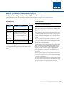
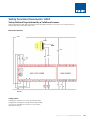
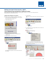
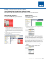
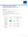
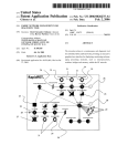
NHP SAFETY REFERENCE GUIDE
440C
SAFETY FUNCTION
DOCUMENTS
SafeZone Scanner with a
Configurable Safety Relay
Application Technique
Safety Function
Documents:
Safety Function: Safety-Related
Stop
Initiated 440C
by a SafeZone
Safety-Related Stop Initiated by a SafeZone Scanner
Scanner
Products: Guardmaster 440C-CR30 Configurable Safety Relay, 442L SafeZone Laser Scanner,
100S-C Safety Contactors
Safety Rating:
CAT.Relay,
3, PLd442L
to ISOSafeZone
13849-1: Laser
2008 Scanner, 100S-C Safety Contactors
Products: Guardmaster 440C-CR30 Configurable
Safety
Safety Rating: CAT. 3, PLd to ISO 13849-1: 2008
Topic
Page
Important User Information
General Safety Information
Introduction
Safety Function Realization: Risk Assessment
2
Table of Contents:
3
3
3
Safety Function Requirements
3
Important User Information
4
Introduction 4
Functional Safety Description
4
General Safety Information
4
Bill of Material
5
Safety Function Realization: Risk Assessment
5
Area Scanner Single Zone6Safety Function
Area Scanner Single Zone Safety Function
Setup and Wiring
Configuration
Calculation of the Performance Level
3
5
5
5
Verification of the Configuration
24
Safety Function Requirements
26
Functional Safety Description
29
Additional Resources
Bill of Material
6
Verification and Validation Plan
31
5
Setup and Wiring
6
Configuration 7
Calculation of the Performance Level
17
Verification and Validation Plan
19
Verification of the Configuration
22
Additional Resources
23
NHP Safety Reference Guide > Safety Function Documents: 440C
6A-2
Safety Function Documents: 440C
Safety-Related Stop Initiated by a SafeZone Scanner
Products: Guardmaster 440C-CR30 Configurable Safety Relay, 442L SafeZone Laser Scanner, 100S-C Safety Contactors
Safety Rating: CAT. 3, PLd to ISO 13849-1: 2008
Introduction
Important User Information
This safety function application technique explains how to wire
and configure a Guardmaster® 440C-CR30 configurable safety
relay to monitor both an E-Stop and a SafeZone™ laser scanner.
If an object intrudes into the SafeZone laser-scanner sensing
field, if the E-Stop is actuated or if a fault is detected in the
monitoring circuit, the 440C-CR30 relay de-energizes the final
control devices, in this case, a pair of 100S-C safety contactors.
The safety scanner can be used in either vertical or horizontal
applications to detect the intrusion of personnel or objects into
the sensing field. You configure the safety scanner’s warning and
safety fields by using the Safety Configuration and Diagnostics
(SCD) software supplied with each scanner.
Read this document and the documents listed in the additional
resources section about installation, configuration, and
operation of this equipment before you install, configure,
operate, or maintain this product. Users are required to
familiarize themselves with installation and wiring instructions
in addition to requirements of all applicable codes, laws, and
standards.
Activities including installation, adjustments, putting into
service, use, assembly, disassembly, and maintenance are
required to be carried out by suitably trained personnel in
accordance with applicable code of practice.
If this equipment is used in a manner not specified by the
manufacturer, the protection provided by the equipment may
be impaired.
In no event will Rockwell Automation, Inc. be responsible or
liable for indirect or consequential damages resulting from the
use or application of this equipment.
The examples and diagrams in this manual are included
solely for illustrative purposes. Because of the many variables
and requirements associated with any particular installation,
Rockwell Automation, Inc. cannot assume responsibility or
liability for actual use based on the examples and diagrams.
No patent liability is assumed by Rockwell Automation, Inc. with
respect to use of information, circuits, equipment, or software
described in this manual.
Reproduction of the contents of this manual, in whole or in part,
without written permission of Rockwell Automation, Inc., is
prohibited.
NHP Safety Reference Guide > Safety Function Documents: 440C
6A-3
Activities including installation, adjustments, putting into service, use, assembly, disassembly, and maintenance are required
to be carried out by suitably trained personnel in accordance with applicable code of practice.
If this equipment is used in a manner not specified by the manufacturer, the protection provided by the equipment may be
impaired.
In no event will Rockwell Automation, Inc. be responsible or liable for indirect or consequential damages resulting from the
use or application of this equipment.
The examples and diagrams in this manual are included solely for illustrative purposes. Because of the many variables and
requirements associated with any particular installation, Rockwell Automation, Inc. cannot assume responsibility or
liability for actual use based on the examples and diagrams.
Safety Function Documents: 440C
Safety-Related Stop Initiated by a SafeZone Scanner
No patent liability is assumed by Rockwell Automation, Inc. with respect to use of information, circuits, equipment, or
Products: Guardmaster 440C-CR30 Configurable Safety Relay, 442L SafeZone Laser Scanner, 100S-C Safety Contactors
software
described
inPLd
thisto
manual.
Safety
Rating:
CAT. 3,
ISO 13849-1: 2008
Reproduction of the contents of this manual, in whole or in part, without written permission of Rockwell Automation,
Inc., is prohibited.
Important
User Information cont
Throughout
weuse
usenotes
notestotomake
makeyou
youaware
aware
safety
considerations.
Throughoutthis
thismanual,
manual, when
when necessary,
necessary, we
ofof
safety
considerations.
WARNING: Identifies information about practices or circumstances that can cause an explosion in a hazardous environment,
which may lead to personal injury or death, property damage, or economic loss.
ATTENTION: Identifies information about practices or circumstances that can lead to personal injury or death, property
damage, or economic loss. Attentions help you identify a hazard, avoid a hazard, and recognize the consequence.
IMPORTANT
Identifies information that is critical for successful application and understanding of the product.
Labels may also be on or inside the equipment to provide specific precautions.
SHOCK HAZARD: Labels may be on or inside the equipment, for example, a drive or motor, to alert people that dangerous
voltage may be present.
BURN HAZARD: Labels may be on or inside the equipment, for example, a drive or motor, to alert people that surfaces may
reach dangerous temperatures.
ARC FLASH HAZARD: Labels may be on or inside the equipment, for example, a motor control center, to alert people to
potential Arc Flash. Arc Flash will cause severe injury or death. Wear proper Personal Protective Equipment (PPE). Follow ALL
Regulatory requirements for safe work practices and for Personal Protective Equipment (PPE).
Contact
NHP to find out more aboutRockwell
our safety
riskPublication
assessment
services. - September 2014
2
Automation
SAFETY-AT134A-EN-P
Safety Function: Cable Pull Switch with a Configurable Safety Relay
General Safety Information
General Safety Information
Contact Rockwell Automation to find out more about our safety risk assessment services.
Contact Rockwell Automation to find out more about our safety risk assessment services.
IMPORTANT
This application example is for advanced users and assumes that you are trained and experienced in safety system requirements.
ATTENTION: Perform a risk assessment to make sure all task and hazard combinations have been identified and addressed. The risk
assessment can require additional circuitry to reduce the risk to a tolerable level. Safety circuits must take into consideration safety
distance calculations, which are not part of the scope of this document.
Introduction
This safety function application technique explains how to wire, configure, and integrate a Lifeline™ 4 cable pull switch,
and an E-stop with a Guardmaster® 440C-CR30 configurable safety relay and two safety contactors. When the Lifeline 4
cable pull switch is tripped, the E-stop is pressed, or a fault is detected, the 440C-CR30 relay turns off two outputs, which
then turn off two safety contactors and remove power from the motor.
NHP Safety Reference Guide > Safety Function Documents: 440C
6A-4
Safety Function: Cable Pull Switch with a Configurable Safety Relay
neral Safety Information
tact Rockwell Automation to find out more about our safety risk assessment services.
PORTANT
This application example is for advanced users and assumes that you are trained and experienced in safety system requirements.
ATTENTION: Perform a risk assessment to make sure all task and hazard combinations have been identified and addressed. The risk
assessment can require additional circuitry to reduce the risk to a tolerable level. Safety circuits must take into consideration safety
distance calculations, which are not part of the scope of this document.
roduction
Safety Function Documents: 440C
Safety-Related Stop Initiated by a SafeZone Scanner
Products: Guardmaster 440C-CR30 Configurable Safety Relay, 442L SafeZone Laser Scanner, 100S-C Safety Contactors
Safety Rating: CAT. 3, PLd to ISO 13849-1: 2008
s safety function application technique explains how to wire, configure, and integrate a Lifeline™ 4 cable pull switch,
an E-stop with a Guardmaster®
440C-CR30
configurable safety
and two safety contactors. When
the Lifeline
4
Safety Function
Realization:
Riskrelay
Assessment
Safety
Function
Requirements
e pull switch is tripped, the E-stop is pressed, or a fault is detected, the 440C-CR30 relay turns off two outputs, which
The
requiredand
performance
level
themotor.
result of a risk assessment
Interrupting the configured sensing zone of the laser scanner
turn off two safety
contactors
remove power
fromisthe
and refers to the amount of the risk reduction to be carried out
stops and prevents hazardous motion by removing power to the
by the safety-related parts of the control system. Part of the risk
motor. The motor coasts to a stop (Stop Category 0). When the
reduction process is to determine the safety functions of the
scanner is reset, hazardous motion and power to the motor do
machine. In this application, the performance level required
not resume until a secondary action occurs—the Start button
(PLr) by the risk assessment is Category 3, Performance Level d
is depressed. A fault at the laser scanner is detected before
(CAT.level
3, PLd),
each
function.and
A safety
system
that of the risk reduction
the next
required performance
is thefor
result
of safety
a risk assessment
refers to
the amount
to besafety
carrieddemand. The safe distance from the location
achieves
CAT.
3,
PLd,
or
higher,
can
be
considered
control
of
the
laser
scanner
to the hazard must be established per
by the safety-related parts of the control system. Part of the risk reduction process is to determine the safety functions
of
reliable. Each
safety product
its own
rating
and
be
13855:2010 such that hazardous motion must be stopped
machine. In this application,
the performance
levelhas
required
(PLr)
by the
riskcan
assessment
is CategoryISO
3, Performance
to create
a safety
function
meets or
exceeds
the
before
the user can reach the hazard.
el d (CAT. 3, PLd),combined
for each safety
function.
A safety
system that
that achieves
CAT.
3, PLd,
or higher, can
be considered
rol reliable. Each safety
meets the
or E-Stop button stops hazardous motion by
PLr. product has its own rating and can be combined to create a safety function that
Pressing
eds the PLr.
removing power to the motor. Releasing the E-Stop does not
fety Function Realization: Risk Assessment
From: Risk Assessment (ISO 12100)
restart hazardous motion. Once the Reset button is pressed and
all faults are cleared, the system is enabled to accept a separate
Start command.
1. Identification of safety functions
The safety functions in this application technique each meet the
requirements for Category 3, Performance Level d (CAT. 3, PLd),
per ISO 13849-1 and control reliable operation per ANSI B11.19.
2. Specification of characteristics of each function
3. Determination of required PL (PLr) for each safety function
To: Realization and PL Evaluation
Area Scanner Single Zone Safety Function
This application technique includes two safety functions:
1.Safety-related stop function initiated by presence in the
protective
areaAutomation
of the safety
Rockwell
Publicationscanner.
SAFETY-AT134A-EN-P - September 2014
2. Safety-related stop function initiated by actuation of an
E-Stop button.
Functional Safety Description
Hazardous motion is stopped or prevented by interrupting the
sensing field of the SafeZone laser scanner. The laser scanner
and the E-Stop are connected to the Guardmaster 440C-CR30
software configurable safety relay. The 440C-CR30 relay provides
two solid-state safety outputs that control power to the 100S-C
contactor coils. Whenever the 440C-CR30 relay disables its
outputs, hazardous motion is stopped. When all safety input
signals are correct, no faults are detected, and the Reset button
is pressed, the 440C-CR30 is enabled to accept a separate Start
command.
The E-Stop is connected to the 440C-CR30 relay inputs EI_00
3
and EI_01, which uses pulse-checking to monitor the EStop for
actuation and faults. Whenever the E-Stop is actuated, the 440CCR30 relay disables its safety outputs and hazardous motion
is stopped. When all safety input signals are correct, no faults
are detected, and the Reset button is pressed (for 0.25…3.0
seconds), then released, the 440C-CR30 relay re-energizes
its safety outputs EO_18 and EO_19 providing power to the
contactor coils.
In summary, when the laser scanner is blocked or the E-Stop
is actuated, the contactors drop out. When the laser scanner
is unblocked, the E-Stop is released, and the reset button is
pressed, the contactors are energized.
NHP Safety Reference Guide > Safety Function Documents: 440C
6A-5
Safety Function Documents: 440C
Safety-Related Stop Initiated by a SafeZone Scanner
Products: Guardmaster 440C-CR30 Configurable Safety Relay, 442L SafeZone Laser Scanner, 100S-C Safety Contactors
Safety Rating: CAT. 3, PLd to ISO 13849-1: 2008
Bill of Material
System Overview
This application uses these products.
Cat. No.
Description
Quantity
442L-SFZNMZ
SafeZone multizone scan head and I/O module
1
442L-CSFZNMZ-10
10M prewired 13 conductor memory module
1
442L-ACUSB-2
2 meter RS232 programming cable with USB
connector
1
440C-CR30-22BBB
Guardmaster 440C-CR30 software configured safety
relay, PLe SIL 3, 22 safety I/O, embedded serial port,
USB programming port, 2 plug-in slots, 24V DC
1
800F-1YP8
800F 1-hole enclosure E-Stop station, plastic, PG,
twist-to-release 60 mm, non-illuminated, 1 N.O. /
2 N.C.
1
800FM-G611MX10
800F push button, metal, guarded, blue, R, metal
latch mount, 1 N.O. contact, 0 N.C. contacts, standard
1
100S-C09EJ23BC
Modular Control System (MCS) 100S-C safety
contactor, 9 A, 24V DC (with electrical coil), bifurcated
contact
2
Setup and Wiring
For detailed information on installing and wiring, refer to the
publications listed in the Additional Resources on the back
cover.
INFORMATION: A multizone scanner, configured as a singlezone
scanner, was used in this safety function.
The Guardmaster 440C-CR30 software configurable safety relay
monitors the input from the SafeZone laser scanner control and
the E-Stop. The laser scanner control provides two PNP outputs
that are de-energized when an object interrupts the field of
view.
When an intrusion in the SafeZone sensing area is detected, a
pair of 100S-C safety contactors, K1 and K2, are deenergized.
The contactors are controlled by the 440C-CR30 relay. These are
wired in a redundant configuration and are tested on startup
for faults.
These de-energized contactors remove power to the motor
and the motor coasts to a stop (Stop Category 0). When the
laser scanner control returns to the non-interrupted state, the
contactors in the output do not energize until the system is
reset by a momentary push button.
The 440C-CR30 relay also monitors the E-Stop circuit for faults.
Open-circuit faults, shorts to 24V DC, shorts to GND, output
faults, and cross-channel faults are detected. When a fault is
detected, or when the E-Stop is actuated, the 440CCR30
relay responds by de-energizing the 100S-C contactor coils,
removing power to the motor. The motor coasts to a stop (Stop
Category 0).
Two N.C. contacts, one from each of the safety contactors, are
connected as part of the reset circuit. The outputs of the 440CCR30 relay can only be energized if both safety contactors are in
a proper de-energized state.
The system is to be designed such that no single fault results in
the safety system failing to perform its safety function. A single
fault is detected before the next demand on the safety system.
The system cannot be reset until the fault is corrected.
NHP Safety Reference Guide > Safety Function Documents: 440C
6A-6
Safety Function Documents: 440C
Safety-Related Stop Initiated by a SafeZone Scanner
Products: Guardmaster 440C-CR30 Configurable Safety Relay, 442L SafeZone Laser Scanner, 100S-C Safety Contactors
Safety Rating: CAT. 3, PLd to ISO 13849-1: 2008
Safety Function: Safety-Related Stop Initiated by a SafeZone Scanner
Electrical Schematic
Electrical Schematic
24V DC
BROWN
BLUE
RESET
PINK
GREY
0V DC
Configuration
Configuration
Configure the
Safety
Configure
theSafeZone
SafeZonelaser
laserscanner
scannerbybyusing
usingthethe
Safety Configuration and Diagnostics (SCD) software supplied with
Configuration and Diagnostics (SCD) software supplied with
each scanner. SCD software, revision 3.0.0, is used in this application technique.
each scanner. SCD software, revision 3.0.0, is used in this
application technique.
Configure the SafeZone Laser Scanner
Follow these steps to configure the SafeZone laser scanner.
NHP Safety Reference Guide > Safety Function Documents: 440C
1. Connect the scanner’s USB cable to the PC and verify that the correct Com port is set on the PC.
6A-7
3. To go online, locate your project and expand Serial communication.
4. Right-click Com2 and choose Connect.
Safety Function Documents: 440C
Safety-Related Stop Initiated by a SafeZone Scanner
Products: Guardmaster 440C-CR30 Configurable Safety Relay, 442L SafeZone Laser Scanner, 100S-C Safety Contactors
Safety Rating: CAT. 3, PLd to ISO 13849-1: 2008
Configure the SafeZone Laser Scanner
The Configuration
searches for and connects to the scanner.
5. Clicksoftware
Continue.
When the connection is made, the scanner name appears in
Follow these steps to configure the SafeZone laser scanner.
5. Click Continue.
Blue.
1. Connect the scanner’s USB cable to the PC and verify that
Safety
Function:
Safety-Related Stop
Initiatedthe
by ascanner
SafeZone Scanner
When
the connection
is made,
name appears in Blue.
the correct Com port is set on the
PC.
Safety Function: Safety-Related Stop Initiated by a SafeZone Scanner
TIP This example uses the Com2 port.
2. Start the SCD
2. software.
Start the SCD software.
D software.
Safety Function: Safety-Related Stop Initiated by a SafeZone Scanner
6. To configure the scanner, right-click the scanner and choose
Open
device window.
6. To configure the scanner,
right-click
the scanner and choose Open device window.
Rockwell Automation Publication SAFETY-AT137A-EN-P - March 2015
Safety Function: Safety-Related Stop Initiated by a SafeZone Scanner
locate your project
Seriallocate
communication.
3. and
Toexpand
go online,
your project and expand Serial
communication.
om2Toand
3.
gochoose
online,Connect.
locate your project and expand Serial communication.
6. To configure the scanner, right-click the scanner and choose Open device window.
4. Right-click Com2 and choose Connect.
4. Right-click Com2 and choose Connect.
The device window opens. This window provides the Arc
drawing tool, which lets you configure the protective and
The device window opens. This window provides the Arc drawing tool, which lets you configu
warning
fields
for your
facility.
The device window
opens.
This window
provides
the Arc drawing tool, which lets you configure the protective a
warning fieldswarning
for your
fieldsfacility.
for your facility.
ration software searches for and connects to the scanner.
ue.
nnection is made,
the The
scanner
name appearssoftware
in Blue. searches for and connects to
Configuration
The Configuration
software searches for and connects to the scanner.
the scanner.
5. Click Continue.
When the connection is made, the scanner name appears in Blue.
NHP Safety Reference Guide > Safety Function Documents: 440C
6A-8
Safety Function: Safety-Related Stop Initiated by a SafeZone Scanner
A Progress dialog box appears and displays warning notices for the parameters you set for the scanner.
Safety Function Documents: 440C
Safety-Related Stop Initiated by a SafeZone Scanner
Products: Guardmaster 440C-CR30 Configurable Safety Relay, 442L SafeZone Laser Scanner, 100S-C Safety Contactors
Safety Rating: CAT. 3, PLd to ISO 13849-1: 2008
Configure the SafeZone Laser Scanner cont
10. Review the warning notices, make any necessary
adjustments to the confirmation, and when you are satisfied
with the results, click Continue. A configuration window
Review the warning notices, make any necessary adjustments to the confirmation, and when you are satisfied with
the results,appears.
click Continue.
Safety Function: Safety-Related Stop Initiated by a SafeZone Scanner
7. To configure the protective and warning field, use the Arc
drawing tool.
7. To configure the protective and warning field, use the Arc drawing tool.
10.
A configuration window appears.
Safety Function: Safety-Related Stop Initiated by a SafeZone Scanner
7. To configure the protective and warning field, use the Arc drawing tool.
11. Review the configuration details, and if you are satisfied that the configuration meets your requirements, click
Release.
8. When you finish configuring the protective and warning field, click Transfer to transfer the information to the
8. When you finish configuring the protective and warning
scanner.
field,
Transfer to transfer the information to the
The Transfer
dialogclick
box appears.
scanner.
10
11. Review the configuration details, and if you are satisfied
that the configuration meets your requirements, click
Release. A second Progress dialog
box appears and displays
Safety Function: Safety-Related Stop Initiated by a SafeZone Scanner
information about the transfer progress.
Rockwell Automation Publication SAFETY-AT137A-EN-P - March 2015
A second Progress dialog box appears and displays information about the transfer progress.
8. When you finish configuring the protective and warning field, click Transfer to transfer the information to the
scanner.
The Transfer dialog box appears.
The Transfer dialog box appears.
9. Click Yes.
Click Yes.
9. Click9.
Yes.
A Progress dialog box appears and displays warning notices
for the parameters you set for the scanner.
Safety Function: Safety-Related Stop Initiated by a SafeZone Scanner
A Progress dialog box appears and displays warning notices for the parameters you set for the scanner.
Rockwell Automation Publication SAFETY-AT137A-EN-P - March 2015
9
Rockwell Automation Publication SAFETY-AT137A-EN-P - March 2015
12. Once the transfer is complete, click Continue.
12.Once the transfer is complete, click Continue.
The Progress dialog box closes, and the application returns
you to the main window of the SCD software.
The Progress dialog box closes, and the application returns you to the main window of the SCD software.
9
10. Review the warning notices, make any necessary adjustments to the confirmation, and when you are satisfied with
the results, click Continue.
A configuration window appears.
Rockwell Automation Publication SAFETY-AT137A-EN-P - March 2015
NHP Safety Reference Guide > Safety Function Documents: 440C
11
6A-9
Safety Function Documents: 440C
Safety-Related Stop Initiated by a SafeZone Scanner
Products: Guardmaster 440C-CR30 Configurable Safety Relay, 442L SafeZone Laser Scanner, 100S-C Safety Contactors
Safety Rating: CAT. 3, PLd to ISO 13849-1: 2008
Configure the SafeZone Laser Scanner cont
Configure the 440C-CR30 Relay
Safety Function: Safety-Related Stop Initiated by a SafeZone Scanner
13. To verify that your programmed field is running, select the
Data-Recorder in the Diagnostic group.
13. To verify that your programmed field is running, select the Data-Recorder in the Diagnostic group.
The 440C-CR30 relay is configured by using Connected
Components Workbench™ software, release 6.01 or later.
A detailed description of each step is beyond the scope of
this document. Knowledge of the Connected Components
Workbench software is assumed.
Function: Safety-Related
Stop Initiated by a SafeZone Scanner
Follow these steps to configure the Safety
Guardmaster
440C-CR30
relay by using the Connected Components Workbench
software.
Follow these steps to configure
the Guardmaster 440C-CR30
relay by using the Connected Components Workbench
Safety Function: Safety-Related Stop Initiated by a SafeZone Scanner
software.
1. In Connected Components Workbench software, choose
View
andrelay
then
Device
Toolbox.
Follow these steps
the Guardmaster
by using
the Connected
Components
Workbench
1. to
Inconfigure
Connected
Components440C-CR30
Workbench
software,
choose
View and
then Device
Toolbox.
software.
1. In Connected Components Workbench software, choose View and then Device Toolbox.
2. Select 440C-CR30-22BBB.
2. Select 440C-CR30-22BBB.
2. Select 440C-CR30-22BBB.
The SCD
software
a real-time view
of the status
of the warning
fieldsofyou configured.
The displays
SCD software
displays
a real-time
viewand
ofprotective
the status
the warning and protective fields you configured.
Configure the 440C-CR30 Relay
The 440C-CR30 relay is configured by using Connected Components Workbench™ software, release 6.01 or later. A
detailed description of each step is beyond the scope of this document. Knowledge of the Connected Components
Workbench software is assumed.
Safety Function: Safety-Related Stop Initiated by a SafeZone Scanner
3. In the Project Organizer, double-click the
Guardmaster_440C_CR30 relay.
3. In the Project Organizer, double-click the Guardmaster_440C_CR30 relay.
12
Rockwell Automation Publication SAFETY-AT137A-EN-P - March 2015
Rockwell Automation Publication SAFETY-AT137A-EN-P - March 2015
13
13
Rockwell Automation Publication SAFETY-AT137A-EN-P - March 2015
4. To add the plug-in I/O module called for in the schematic, right-click the left plug-in module space and choose the
2080-IQ4OB4 module.
NHP Safety Reference Guide > Safety Function Documents: 440C
6A-10
6. From the View pull-down menu, choose Toolbox.
Safety Function: Safety-Related Stop Initiated by a SafeZone Scanner
6. From the View pull-down menu, choose Toolbox.
Safety Function Documents: 440C
Safety-Related Stop Initiated by a SafeZone Scanner
Products: Guardmaster 440C-CR30 Configurable Safety Relay, 442L SafeZone Laser Scanner, 100S-C Safety Contactors
Safety Rating: CAT. 3, PLd to ISO 13849-1: 2008
Configure the 440C-CR30 Relay cont
Configure the Inputs
Configure the Inputs
4. To add the plug-in I/O module calledConfigure
for in the
schematic,
Follow
Follow
these steps to configure
thethese
inputs.steps to configure the inputs.
the
Inputs
the left
plug-in module
and module
choose the
1. Select
odule called for in right-click
the schematic,
right-click
the leftspace
plug-in
space and choose
the Emergency Stop.
2080-IQ4OB4 module.
1. Select
Emergency
Stop.
Follow these steps
to configure
the inputs.
1. Select Emergency Stop.
2. Emergency
toSafety
the green
rectangle
underit.Safety
2. Drag Emergency Stop
toDrag
the green
rectangleStop
under
Monitoring
and release
TIP: The I/O module is shown in standard gray2.
because
it is not a safety
Drag Emergency
Stop to the green rectangle
under Safety
Monitoring
and Monitoring
release it.and release it.
module.
a problem
in thisThat
application
because the
hown in standard grayI/O
because
it isThat
not isa not
safety
I/O module.
is not a problem
in this application because
standard
I/O signals.
module Inputs
is not used
safety
Inputs such
odule is not used to connect
safety
suchtoasconnect
Feedback
andsignals.
Reset button
are not considered strict,
as Feedback and Reset button are not considered strict, safety signals.
ing the standard I/O module
for
these
non-safety
signals,
you
can
reserve
the
limited
number of safety inputs
By using the standard I/O module for these non-safety signals, you can
e safety signals.
reserve the limited number of safety inputs and outputs for true safety
signals.
Click Edit Logic
to open the
Connected Components
he Connected 5.
Components
Workbench
Workspace.
Workbench Workspace.
Safety Function: Safety-Related Stop Initiated by a SafeZone Scanner
6. From the View pull-down menu, choose Toolbox.
6. From the View pull-down menu, choose Toolbox.
Connected Components Workbench software has assigned
Connected Components Workbench software has assigned input terminals EI_00 and EI_01 on the left side of the
Connected Components Workbench
software
hasEI_01
assigned
input
terminals
and EI_01 on the l
EI_00
and
on the
left
side The
ofEI_00
the
block.
block. The software automaticallyinput
assignsterminals
the next unused
terminal
for a newly
added
device.
terminals
can be
block. The softwareThe
automatically
assigns
the next unused
terminal
forunused
aisnewly
added device. The term
software
automatically
assigns
the
terminal
changed to any unused input terminal,
but in this case,
leave the default.
Because
annext
E-Stop
an electro-mechanical
changedhas
to automatically
any unused
terminal,
but
in 13
thisasThe
case,
leave the
default.
an E-Stop
is an elect
for ainput
newly
added12
device.
can be
changed
to
device, the software
added
terminals
and
test terminals
sources.
Numbers
12Because
and 13 refer
to multidevice,12the
software
has and
automatically
terminals
as test
sources.
Numbers 12 and 13 r
purpose terminals
and
13 (MP_12
MP_13).
any
unused
inputadded
terminal,
but12
in and
this13
case,
leave
the default.
purpose terminals 12
and 13 (MP_12
andisMP_13).
Because
an E-Stop
an electro-mechanical device, the software
has Automation
automatically
added terminals
Rockwell
Publication SAFETY-AT137A-EN-P
- March 201512 and 13 as test sources.
15
Numbers 12
andAutomation
13 referPublication
to multipurpose
terminals
Rockwell
SAFETY-AT137A-EN-P
- March 2015 12 and 13
Safety Function: Safety-Related Stop Initiated by a SafeZone Scanner
(MP_12 and MP_13).
3. To add the Scanner monitoring block, use a Light curtain
block
forcurtain
the scanner
also uses
typetype
3. To add the Scanner monitoring block, use
a Light
block forbecause
the scanneritbecause
it alsoOSSD
uses OSSD
outputs.
outputs.
Rockwell Automation Publication SAFETY-AT137A-EN-P - March 2015
Configure the Inputs
4. Choose inputs EI_08 and EI_09 for4.the
scanner. inputs EI_08 and EI_09 for the scanner.
Choose
Follow these steps to configure the inputs.
1. Select Emergency Stop.
5. Add a Reset.
2. Drag Emergency Stop to the green rectangle under Safety Monitoring and release it.
6. Change the Reset input to Plug-In input P1_00 to complete the configuration of the inputs.
NHP Safety Reference Guide > Safety Function Documents: 440C
6A-11
a SafeZone Scanner
ated by a SafeZone Scanner
afeZone Scanner
oring block, use a Light curtain block for the scanner because it also uses OSSD type
monitoring block, use a Light curtain block for the scanner because it also uses OSSD type
ing block, use a Light curtain block for the scanner because it also uses OSSD type
EI_09 for the scanner.
8 and EI_09 for the scanner.
I_09 for the scanner.
Safety Function Documents: 440C
Safety-Related Stop Initiated by a SafeZone Scanner
Products: Guardmaster 440C-CR30 Configurable Safety Relay, 442L SafeZone Laser Scanner, 100S-C Safety Contactors
Safety Rating: CAT. 3, PLd to ISO 13849-1: 2008
Configure the Inputs cont
5. Add a Reset.
Configure the Outputs
Configure the Outputs
Follow these steps to configure the safety and diagnostic
outputs
Follow these steps to configure the safety
diagnostic
outputs
1. and
Select
and drag
the Immediate OFF safety output function
block to the top position in the Safety Output column of the
1. Select and drag the Immediate OFF safety
output function block to the top position in the Safety Output column o
Workspace.
the Workspace.
Plug-In input 6.
P1_00
to complete
configuration
of the
inputs.
Change
the Resetthe
input
to Plug-In input
P1_00
to complete
theP1_00
configuration
of thethe
inputs.
put to Plug-In input
to complete
configuration of the inputs.
lug-In input P1_00 to complete the configuration of the inputs.
ng input.
nitoring input. 7. Add a Feedback Monitoring input.
input.
Safety Function: Safety-Related Stop Initiated by a SafeZone Scanner
The software automatically assigns two outputs to the next
Function: Safety-Related Stop Initiated by a SafeZone Scanner
the next available input terminal, which in this caseSafety
is EI_02.
available safety outputs, which in this case are EO_18, and
it to the next available input terminal, which in this case
is software
EI_02. automatically assigns
The
twoand
outputs
to one
the next
available
safety output.
outputs,One,
whichtwo,
in this
EO_19,
leaves
blank,
unassigned
or case are E
e next available
input
case
is EI_02.
and
and
leaves one blank,
unassigned
output.
two, or
three
may
be configured.
Becau
Rockwell
Automation
Publication
SAFETY-AT137A-EN-P
- March
2015outputs
three
outputs
may
beOne,
configured.
Because
we are
using
TheEO_19,
software
automatically
assigns
two
outputs
to the
next
available
safety
outputs,
which
inEO_18
this case are
EO1
Theterminal,
software which
assignsin
it this
to the
next
available
input terminal,
which in this case is EI_02.
using
EO_18 and
andInitiated
EO_19
ourand
outputs,
changes
EO_19noasI/O
our
outputs,
norequired.
I/O
are required.
and
EO_19,
leaves
blank,
unassigned
output.
One,are
two,
orchanges
three outputs
may be configured. Because
Safety Function:
Safety-Related
Stop
byone
a as
SafeZone
Scanner
using
EO_18
and EO_19 as our2.outputs,
nothe
I/OFeedback
changes are
required.
Change
input
to SMF 4.
8. Change the number of inputs to 2, 2.
andChange
use the
Input
the
Feedback input to SMF
4.
pull-down menu to select plug-in inputs
P1_01
and
P1_02
2. Change the Feedback input to SMF 4.
r of inputs to 2, and instead.
use the Input pull-down menu to select plug-in inputs P1_01 and P1_02
3. Change the Reset Input to SMF 3.
3. Change the Reset Input to SMF3.3. Change the Reset Input to SMF 3.
Rockwell Automation Publication SAFETY-AT137A-EN-P - March 2015
Rockwell Automation Publication SAFETY-AT137A-EN-P - March 2015
Rockwell Automation Publication SAFETY-AT137A-EN-P - March 2015
4. Configuration of the safety outputs
is complete. of the safety outputs is complete.
4. Configuration
4. Configuration of the safety outputs is complete.
Configure
Configurethe
theLogic
Logic
NHP Safety Reference Guide > Safety Function Documents: 440C
6A-12
The
respond to
to the
theinputs
inputsininthe
themanner
mannerrequired.
required.
Thelogic
logicties
tiesthe
theinputs
inputsto
tothe
theoutputs,
outputs, making
making the
the outputs
outputs respond
Safety Function Documents: 440C
Safety-Related Stop Initiated by a SafeZone Scanner
Products: Guardmaster 440C-CR30 Configurable Safety Relay, 442L SafeZone Laser Scanner, 100S-C Safety Contactors
Safety Rating: CAT. 3, PLd to ISO 13849-1: 2008
Configure the Logic
The logic ties the inputs to the outputs, making the outputs respond to the inputs in the manner
required.
1. Add an AND function to the Logic Level A.
2. Click the blue dot on the E-Stop input block, and notice that the dot turns gray.
3. Click the blue dot on the LLA1 block to connect the blocks.
4. Connect the output of the Light Curtain block SMF 2 to LLA1.
5. Connect the output of the LLA1 block to the input of the Immediate OFF block SOF 1.
The software automatically adds the Pass Through blocks because no
Logic Functions
Safetyadditional
Function: Safety-Related
Stop Initiated byare
a SafeZone Scanner
being used.
The completed logic looks like this.
The completed logic looks like this.
Configure the Status Indicators
The 440C-CR30 relay lets you configure ten input status indicators and six output status indicators. These status
indicators can be very helpful while testing the system during installation and commissioning. They are also useful for
monitoring the system in operation.
To configure LED status indicators to show the status of the E-Stop (Terminals 00 and 01), and SafeZone laser scanner,
follow these steps.
1. Click Guardmaster_440C_CR30.
NHP Safety Reference Guide > Safety Function Documents: 440C
6A-13
3. Choose Terminal Status as the Type Filter for LED 0.
Safety Function Documents:
3. Choose 440C
Terminal Status as the Type Filter for LED 0.
Safety-Related Stop Initiated by a SafeZone Scanner
Products: Guardmaster 440C-CR30 Configurable Safety Relay, 442L SafeZone Laser Scanner, 100S-C Safety Contactors
Safety Rating: CAT. 3, PLd to ISO 13849-1: 2008
Configure the Status Indicators
4. Select Terminal 00 as the Value for LED 0.
4. Select Terminal 00 as the Value for LED 0.
The 440C-CR30 relay lets you configure ten input status
nfigure the Status
Indicators
indicators and six output status indicators. These status
4. Select Terminal 00 as the Value for LED 0.
indicators can be very helpful while testing the system during
e 440C-CR30 relay lets you configure ten input status indicators and six output status indicators. These status
commissioning.
They
are also
useful
for
icators can be veryinstallation
helpful whileand
testing
the system during
installation
and
commissioning.
They are also useful for
monitoring
the
system
in
operation.
nitoring the system in operation.
To configure LED status indicators to show the status of the
configure LED status
indicators
to show00the
status
the E-Stop
(Terminals
00 and 01),
and SafeZone laser scanner,
E-Stop
(Terminals
and
01),ofand
SafeZone
laser scanner,
follow
ow these steps. these steps.
In this example, the E-Stop inputs
onexample,
are displayed
LED 0inputs
and 1. The
Scanner
inputs are
on LED 2 an
In this
theonE-Stop
on are
displayed
ondisplayed
LED 0 and
3. LED 4 and 5 display the status
of the
Reset and
Feedback
monitoringon
blocks.
1.
The
Scanner
inputs
are
displayed
LED
2
and
3.
LED
4
and
5
1. Click Guardmaster_440C_CR30.
1. Click Guardmaster_440C_CR30.
the status
the
Reset
and 0Feedback
blocks.
5. ConfigureInthe
remaining
LED inputs
status
indicators
as shown.
this
example,Input
thedisplay
E-Stop
on areof
displayed
on LED
and 1. Themonitoring
Scanner inputs
are displayed on
3. LED 4 and 5 display
the status ofthe
the Reset
and Feedback
monitoring
5. Configure
remaining
Input LED
status blocks.
indicators as
6. Configure the Output LED status
indicators as shown.
shown.
5. Configure the remaining Input LED status indicators as shown.
6. LED
Configure
the Output
LED status indicators as shown.
6. Configure the Output
status indicators
as shown.
K1 Coil
K2 Coil
E-Stop SOF
unction: Safety-Related Stop Initiated by a SafeZone Scanner
K1 Coil
K2 Coil
E-Stop SOF
elated Stop Initiated by a SafeZone Scanner
Select LED configuration.
2. Select LED configuration.
D configuration.
Safety Function: Safety-Related Stop Initiated by a SafeZon
Rockwell Automation Publication SAFETY-AT137A-EN-P - March 2015
Safety Function: Safety-Related Stop Initiated by a SafeZon
20
Confirm the Validity of the Build
Confirm
the Validity of the Build Rockwell
Rockwell Automation Publication SAFETY-AT137A-EN-P - March20
2015
19 Automation Publication SAFETY-AT137A-EN-P - March 2015
these steps to confirm the validity of the logic by using
Confirm the Validity ofFollow
the Build
the Build feature in Connected Components Workbench
Follow these steps to confirm the validity of the logic by using the Build feature in Connected Components Workbe
software.
software.
Follow
these steps to confirm
the validity of the logic by using the Build feature in Connected Components Workbe
software.
1. Click Guardmaster_440C_CR30 in the bar above the
1. Click Guardmaster_440C_CR30
in the bar above the Workspace.
Workspace.
1. Click Guardmaster_440C_CR30 in the bar above the Workspace.
2. Click Build.
2. Click Build.
2. Click Build.
Choose Terminal Status as the Type Filter for LED 0.
3. Choose Terminal Status as the Type Filter for LED 0.
rminal Status as the Type Filter for LED 0.
A Build Succeeded message confirms that the configuration is
A Build Succeeded message confirms that the configuration is valid.
valid. confirms that the configuration is valid.
A Build Succeeded message
Select Terminal 00 as the Value for LED 0.
minal 00 as the Value for LED 0.
If an error or omission
is discovered
during a build,
a message is displayed
detailsa the
error so is
that it can be
If an
error or omission
is discovered
during that
a build,
message
corrected.
you correct
the error,
you need
to perform
theisbuild
again.that details the error so that it can be
If
an error After
or omission
is discovered
during
a build,
a message
displayed
displayed that details the error so that it can be corrected. After
corrected. After you correct the error, you need to perform the build again.
you correct the error, you need to perform the build again.
Save and Download the Project
Save and Download the Project
NHP Safety Reference Guide > Safety Function Documents: 440C
Follow these steps to save and download the project.
Follow
theseare
steps
to save and
download
In this example, the E-Stop inputs on are displayed on LED 0 and 1. The Scanner
inputs
displayed
on LED
2 andthe project.
6A-14
Safety Function: Safety-Related Stop Initiated by a SafeZone Scanner
Safety Function: Safety-Related Stop Initiated by a SafeZone Scanner
5. Click Download.
Safety Function: Safety-Related Stop Initiated by a SafeZone Scanner
5. Click Download.
5. Click Download.
Safety Function Documents: 440C
Safety-Related Stop Initiated by a SafeZone Scanner
Products: Guardmaster 440C-CR30 Configurable Safety Relay, 442L SafeZone Laser Scanner, 100S-C Safety Contactors
Safety Rating: CAT. 3, PLd to ISO 13849-1: 2008
Save and Download the Project
6. In the Connection Browser, expand the AB_VBP-1 Virtual
Chassis
select theVirtual
Guardmaster
440C-CR30-22BBB.
6. In the Connection Browser,
expandand
the AB_VBP-1
Chassis and
select the Guardmaster 440C-CR30Follow these steps to save and download the project.
22BBB.
1. From the File menu, choose Save as to save
project. Browser, expand the AB_VBP-1 Virtual Chassis and select the Guardmaster 440C-CR306. In the
the Connection
22BBB.
6. In the Connection Browser, expand the AB_VBP-1 Virtual Chassis and select the Guardmaster 440C-CR30INFORMATION: Saving the project with a new name
closes the
22BBB.
workspace windows.
2. In the Project Organizer window, double-click
Guardmaster_440C_CR30 to open the workspace.
3. Power up the 440C-CR30 safety relay.
ion: Safety-Related Stop Initiated by a SafeZone Scanner
lick Download.
4. Connect the USB cable to the 440C-CR30 relay.
5. Click Download.
7. Click OK.
7. Click
8. Click Yes to change from
Run toOK.
Program mode.
7. Click OK.
8. Click Yes to change from Run to Program mode.
7. Click
8. Click
Yes toOK.
change from Run to Program mode.
8. Click Yes to change from Run to Program mode.
9. When the download is complete, click Yes to change from Program to Run mode.
When
download
is complete,
click Yes to change from
9. When the download is complete,9.click
Yes to the
change
from Program
to Run mode.
tochange
Run mode.
9. When the download is complete,Program
click Yes to
from Program to Run mode.
n the Connection Browser, expand the AB_VBP-1 Virtual Chassis and select the Guardmaster 440C-CR302BBB.
22
22
Rockwell Automation Publication SAFETY-AT137A-EN-P - March 2015
Rockwell Automation Publication SAFETY-AT137A-EN-P - March 2015
22
Rockwell Automation Publication SAFETY-AT137A-EN-P - March 2015
lick OK.
lick Yes to change from Run to Program mode.
When the download is complete, click Yes to change from Program to Run mode.
NHP Safety Reference Guide > Safety Function Documents: 440C
6A-15
Safety Function Documents: 440C
Safety-Related Stop Initiated by a SafeZone Scanner
Products: Guardmaster 440C-CR30 Configurable Safety Relay, 442L SafeZone Laser Scanner, 100S-C Safety Contactors
Safety Rating: CAT. 3, PLd to ISO 13849-1: 2008
Save and Download the Project cont
Safety Function: Safety-Related Stop Initiated by a SafeZone Scanner
10. Click Edit Logic to see the online diagnostics.
10. Click Edit Logic to see the online diagnostics.
Greenindicates
indicates that
a block
is True
or thator
anthat
inputan
or input
output or
terminal
is ON.
Flashing
indicates that
a Safety
Green
that
a block
is True
output
terminal
is green
ON. Flashing
green
indicates
Output
Function
is
ready
to
be
Reset.
that a Safety Output Function is ready to be Reset.
Theonline
online diagnostics
mode
of theof440C-CR30
relay canrelay
be very
helpful
during
the verification
process.
The
diagnostics
mode
the 440C-CR30
can
be very
helpful
during the
verification
11.process.
Review the information in Calculation of the Performance Level on page 24 and Verification and Validation Plan on
page 26 before proceeding with Verification of the Configuration on page 29.
11. Review the information in Calculation of the Performance Level on page 24 and Verification and
Validation Plan on page 26 before proceeding with Verification of the Configuration on page 29.
Rockwell Automation Publication SAFETY-AT137A-EN-P - March 2015
23
NHP Safety Reference Guide > Safety Function Documents: 440C
6A-16
Safety Function Documents: 440C
Safety-Related Stop Initiated by a SafeZone Scanner
Products: Guardmaster 440C-CR30 Configurable Safety Relay, 442L SafeZone Laser Scanner, 100S-C Safety Contactors
Safety
Rating: CAT. 3, PLd to ISO 13849-1: 2008
Safety Function: Safety-Related Stop Initiated by a SafeZone Scanner
Safety Function: Safety-Related Stop Initiated by a SafeZone Scanner
Safety Function: Safety-Related Stop Initiated by a SafeZone Scanner
Calculation
Level
Calculationofofthe
thePerformance
Performance
Level
Calculation of the Performance Level
Calculation of the Performance Level
When properly implemented, these safety functions can achieve a safety rating of Category 3,
Performance
d (CAT. 3,these
PLd),
according
tocan
ISOachieve
13849-1:
2008,
as calculated
the SISTEMA
When properlyLevel
implemented,
safety
functions
a safety
rating
of Categoryby
3, using
Performance
Level d (CAT.
software
PL
calculation
tool.
3,
PLd),
according
to
ISO
13849-1:
2008,
as
calculated
by
using
the
SISTEMA
software
PL
calculation
tool.
When properly implemented, these safety functions can achieve a safety rating of Category 3, Performance
Level d (CAT.
When
implemented,
these safety
canby
achieve
safety
rating ofsoftware
Category
Performance
Level d (CAT.
3, PLd),properly
according
to ISO 13849-1:
2008, functions
as calculated
using athe
SISTEMA
PL3,calculation
tool.
3, PLd), according to ISO 13849-1: 2008, as calculated by using the SISTEMA software PL calculation tool.
The Performance
Performance Level
and
Category
achieved
by each
of the SafeZone
scannerlaser
safety
function,
as
The
Level
and
Category
achieved
bysubsystem
each subsystem
of the laser
SafeZone
scanner
safety
calculated
by SISTEMA,
is shown below.
The
Performance
Level and
achieved
by each
subsystem of the SafeZone laser scanner safety function, as
function,
as calculated
byCategory
SISTEMA,
is shown
below.
The
Performance
Level and
Category
achieved by each subsystem of the SafeZone laser scanner safety function, as
calculated
by SISTEMA,
is shown
below.
calculated by SISTEMA, is shown below.
The Performance Level and Category achieved by each subsystem of the emergency stop safety function, as calculated by
SISTEMA,
is shown
below.
The Performance
Level
and Category achieved by each subsystem of the emergency stop safety function, as calculated by
The
Performance
Level
and
Category
achieved
bysubsystem
each subsystem
of the emergency
stop safety
function,
The
Performance
Level
and
Category
achieved
by each
of the emergency
stop safety function,
as calculated
by
SISTEMA,
is shown
below.
as
calculated
by
SISTEMA,
is
shown
below.
SISTEMA, is shown below.
24
Rockwell Automation Publication SAFETY-AT137A-EN-P - March 2015
24
24
Rockwell Automation Publication SAFETY-AT137A-EN-P - March 2015
Rockwell Automation Publication SAFETY-AT137A-EN-P - March 2015
NHP Safety Reference Guide > Safety Function Documents: 440C
6A-17
Safety Function Documents: 440C
Safety-Related Stop Initiated by a SafeZone Scanner
Products: Guardmaster 440C-CR30 Configurable Safety Relay, 442L SafeZone Laser Scanner, 100S-C Safety Contactors
Safety Rating: CAT. 3, PLd to ISO 13849-1: 2008
Safety Function: Safety-Related Stop Initiated by a SafeZone Scanner
Calculation of the Performance Level cont
The E-Stop safety function can be modeled as follows.
The E-Stop safety function can be modeled as follows.
Input
• Mean
Safety Function: Safety-Related Stop Initiated by a SafeZone
Scanner
Logic
Output
Logic
Output
100S-C
K1
E-Stop 1
440C-CR30
Relay
E-Stop21
E-Stop
440C-CR30
Relay
E-Stop 2 1
Subsystem
Subsystem 2
Subsystem 2
100S-C
K2
Subsystem
3
Subsystem 3
The presence-sensing
SafeZone laser scanner safety function
Input
Logic
Output
can be modeled as follows.
The presence-sensing SafeZone laser scanner safety function can be modeled as follows.
Input
Logic
Output
100S-C
K1
SafeZone
Laser Scanner
440C-CR30
Relay
SafeZone
Laser Scanner
440C-CR30
Relay
Subsystem 1
Subsystem 2
Electro-mechanical devices’ functional safety evaluations
include the following:
• How frequently they are operated
• Whether they are effectively monitored for faults
100S-C
100S-C
K1
K2
The presence-sensing SafeZone laser scanner safety function can be modeled as follows.
Subsystem 1
Time to Failure, dangerous (MTTFd)
• Diagnostic Coverage (DCavg)
• Common Cause Failure (CCF)
The E-Stop safety function can be modeled as follows.
Input
Because these are electro-mechanical devices, the safety
contactor data includes the following:
100S-C
100S-C
K1
K2
100S-C
K2
Subsystem
3
• Whether they are properly specified and installed
SISTEMA calculates the MTTFd by using B10d data provided
for the contactors along with the estimated frequency of use,
entered during the creation of the SISTEMA project.
The DCavg (99%) for the contactors is selected from the Output
Device table of ISO 13849-1 Annex E, Direct Monitoring. The
DCavg (99%) for the E-Stop is selected from the Input Device
table of ISO 13849-1 Annex E, Cross Monitoring.
The CCF value is generated by using the scoring process
outlined in Annex F of ISO 13849-1. The complete CCF scoring
process must be performed when actually implementing an
application. A minimum score of 65 must be achieved.
The Emergency Stop function is a complementary protective
measure which is intended to be used with other safeguarding
measures and protective devices to sufficiently reduce risk. The
emergency stop function shall be designed not to impair the
effectiveness of the other protective devices or safety functions.
For emergency stop devices in accordance with IEC 60947- 5-5,
a fault exclusion for mechanical aspects is allowed up to PLd if
the maximum number of operations is considered. However,
the actual number of operations (NOP) is used for the purposes
of the MTTFd calculation in this document.
Because these are electro-mechanical devices, the safety contactor data includes the following:
Subsystem 1
Subsystem 3
Subsystem 2
• Mean Time to Failure, dangerous (MTTFd)
• Diagnostic Coverage (DCavg)
Because
these areCause
electro-mechanical
• Common
Failure (CCF)devices, the safety contactor data includes the following:
• Mean Time to Failure, dangerous (MTTFd)
Electro-mechanical
devices' functional
• Diagnostic Coverage
(DCavg) safety evaluations include the following:
How frequently
they are
operated
• •Common
Cause Failure
(CCF)
• Whether they are effectively monitored for faults
Electro-mechanical
devices'
functional
safety evaluations
include the following:
• Whether they
are properly
specified
and installed
• How frequently they are operated
SISTEMA
calculates
theare
MTTFd
by using
B10d data
provided for the contactors along with the estimated frequency of
• Whether
they
effectively
monitored
for faults
use, entered
during the
of thespecified
SISTEMA
• Whether
theycreation
are properly
andproject.
installed
SISTEMA calculates the MTTFd by using B10d data provided for the contactors along with the estimated frequency of
use, entered during the creation of theRockwell
SISTEMA
project.
Automation
Publication SAFETY-AT137A-EN-P - March 2015
25
Rockwell Automation Publication SAFETY-AT137A-EN-P - March 2015
25
NHP Safety Reference Guide > Safety Function Documents: 440C
6A-18
Safety Function Documents: 440C
Safety-Related Stop Initiated by a SafeZone Scanner
Products: Guardmaster 440C-CR30 Configurable Safety Relay, 442L SafeZone Laser Scanner, 100S-C Safety Contactors
Safety Rating: CAT. 3, PLd to ISO 13849-1: 2008
Verification and Validation Plan
Verification and validation play important roles in the avoidance
of faults throughout the safety system design and development
process. ISO 13849-2 sets the requirements for verification and
validation. The standard calls for a documented plan to confirm
that all of the safety functional requirements have been met.
Verification is an analysis of the resulting safety control system.
The Performance Level (PL) of the safety control system is
calculated to confirm that the system meets the required
Performance Level (PLr) specified. The SISTEMA software is
typically used to perform the calculations and assist with
satisfying the requirements of ISO 13849-1.
Verification and Validation is a functional test of the safety
control system to demonstrate that the system meets the
specified requirements of the safety function. The safety
control system is tested to confirm that all of the safety-related
outputs respond appropriately to their corresponding safetyrelated inputs. The functional test includes normal operating
conditions in addition to potential fault injection of failure
modes. A checklist is typically used to document the validation
of the safety control system.
Prior to validating the system, confirm that the Guardmaster
440C-CR30 configurable safety relay has been wired and
configured in accordance with the installation instructions.
NHP Safety Reference Guide > Safety Function Documents: 440C
6A-19
Safety Function Documents: 440C
Safety-Related Stop Initiated by a SafeZone Scanner
Products: Guardmaster 440C-CR30 Configurable Safety Relay, 442L SafeZone Laser Scanner, 100S-C Safety Contactors
Safety Rating: CAT. 3, PLd to ISO 13849-1: 2008
Verification and Validation Checklist
GENERAL MACHINERY INFORMATION
Machine Name / Model Number
Machine Serial Number
Customer Name
Test Date
Tester Name(s)
Schematic Drawing Number
Configurable Safety Relay
Safety Wiring and Relay Configuration Verification
Test Step
Verification
1
Visually inspect the 440C-CR30 circuit to verify that it is wired as documented in the schematics.
2
Visually inspect the SafeZone laser scanner to verify that it is wired as documented.
Pass/Fail
Changes/Modifications
Normal Operation Verification - The 440C-CR30 configurable safety relay responds properly to all normal Start, Stop, Reset, and E-Stop commands.
Test Step
Verification
Pass/Fail
1
Initiate a Start command. Both contactors energize for a normal machine run condition. Verify proper machine-status indication and 440C-CR30
relay status indication.
2
Initiate a Stop command. Both contactors de-energize for a normal machine Stop condition. Verify proper machine-status indication and 440CCR30 relay status indication.
3
While the system is running, interrupt the SafeZone laser scanner. Both contactors are de-energized and open for a normal safe condition. Verify
proper machine-status indication and 440C-CR30 relay status indication if configured.
4
While the system is stopped, interrupt the SafeZone laser scanner and initiate a Start command. Both contactors remain de-energized and open
for a normal safe condition. Verify proper machine-status indication and 440C-CR30 relay status indication.
5
Initiate a Reset command. Both contactors remain de-energized. Verify proper machine-status indication and 440C-CR30 relay status
indication.
Changes/Modifications
Validation of Safe Response to Abnormal Operation - The safety system responds properly to all foreseeable faults with corresponding diagnostics.
SafeZone Laser Scanner
Test Step
Validation
Pass/Fail
1
While the system is running, remove the channel 1 wire from the input EI_08. Both contactors de-energize. Verify proper machine-status
indication and 440C-CR30 relay status indication. Repeat for channel 2.
2
While the system is running, short channel 1 terminal EI_08 of the 440C-CR30 relay to 24V DC. Both contactors de-energize. Verify proper
machine-status indication and 440C-CR30 relay status indication. Repeat for channel 2.
3
While the system is running, short channel 1 terminal EI_08 of the 440C-CR30 relay to 0V DC. Both contactors de-energize. Verify proper
machine-status indication and 440C-CR30 relay status indication. Repeat for channel 2.
4
While the system is running, short channels 1 and 2 (terminal EI_08 and 09) of the 440C-CR30 relay. Both contactors are de-energized. Verify
proper machinestatus indication and 440C-CR30 relay status indication.
Changes/Modifications
Validation of Safe Response to Abnormal Operation - The safety system responds properly to all foreseeable faults with corresponding diagnostics.
Safety Contactor Output Tests
Test Step
Validation
1
While the system is running, remove the contactor feedback from the safety relay. All contactors remain energized. Initiate a Stop command
followed by a Reset command. The relay does not restart or reset. Verify proper machine status indication and 440C-CR30 relay status indication.
Pass/Fail
Changes/Modifications
NHP Safety Reference Guide > Safety Function Documents: 440C
6A-20
Safety Function Documents: 440C
Safety-Related Stop Initiated by a SafeZone Scanner
Products: Guardmaster 440C-CR30 Configurable Safety Relay, 442L SafeZone Laser Scanner, 100S-C Safety Contactors
Safety Rating: CAT. 3, PLd to ISO 13849-1: 2008
Verification and Validation Checklist – E-Stop Safety Function
GENERAL MACHINERY INFORMATION
Machine Name / Model Number
Customer Name
Test Date
Tester Name(s)
Schematic Drawing Number
Configurable Safety Relay
Safety Wiring and Relay Configuration Verification
Test Step
Verification
1
Visually inspect the safety relay circuit to verify that it is wired as documented in the schematics.
2
Visually inspect the 440C-CR30 rotary switch settings to verify that they are correct as documented.
Pass/Fail
Changes/Modifications
Normal Operation Verification - The safety system responds properly to all normal Start, Stop, E-Stop, and Reset commands.
Test Step
Verification
1
Initiate a Start command. Both contactors energize for a normal machine run condition. Verify proper machine-status indication and 440C-CR30
relay status indication.
Pass/Fail
2
Initiate a Stop command. Both contactors de-energize for a normal machine Stop condition. Verify proper machine-status indication and 440CCR30 relay status indication.
3
While the system is running, press the E-Stop button. Both contactors deenergize and open for a normal safe condition. Verify proper machinestatus indication and 440C-CR30 relay status indication. Repeat for all E-Stop buttons.
4
While the system is stopped, press the E-Stop button and initiate a Start command. Both contactors remain de-energized and open for a normal
safe condition. Verify proper machine-status indication and 440C-CR30 relay status indication. Repeat for all E-Stop buttons.
5
Initiate a Reset command. Both contactors remain de-energized. Verify proper machine-status indication and 440C-CR30 relay status
indication.
Changes/Modifications
Validation of Safe Response to Abnormal Operation – The safety system responds properly to all foreseeable faults with corresponding diagnostics.
E-Stop Input Tests
Test Step
Validation
Pass/Fail
1
While the system is running, remove the channel 1 EI_00 wire from the 440CCR30 relay input. Both contactors de-energize. Verify proper
machine-status indication and 440C-CR30 relay status indication. Repeat for channel 2.
2
While the system is running, short channel 1 terminal EI_00 to 24V DC. Both contactors de-energize. Verify proper machine-status indication
and 440CCR30 relay status indication. Repeat for channel 2.
3
While the system is running, short channel 1 terminal EI_00 to 0V DC. Both contactors de-energize. Verify proper machine-status indication and
440CCR30 relay status indication. Repeat for channel 2.
4
While the system is running, short channel 1 and 2, EI_00 to EI_01. Both contactors de-energize. Verify proper machine-status indication and
440CCR30 relay status indication.
Changes/Modifications
Validation of Safe Response to Abnormal Operation - The safety system responds properly to all foreseeable faults with corresponding diagnostics.
Safety Contactor Output Tests
Test Step
Validation
Pass/Fail
1
While the system is running, remove the contactor feedback from the safety relay. All contactors remain energized. Initiate a Stop command
followed by a Reset command. The relay does not restart or reset. Verify proper machinestatus indication and 440C-CR30 relay status indication.
Changes/Modifications
NHP Safety Reference Guide > Safety Function Documents: 440C
6A-21
5
Release the 440C-CR30 relay Reset button. The 440C-CR30 relay must not
respond and the K1 contactor must not activate.
6
Cycle power to the 440C-CR30 relay. The red 440C-CR30 relay Fault status LED
should be OFF.
7
Press, but do not release the 440C-CR30 relay Reset button. The 440C-CR30
relay must not respond and the K1contactor must not activate.
8
Release the 440C-CR30 relay Reset button. The 440C-CR30 relay must respond
and activate the K1 contactor.
9
While the machine is running, short the A1 terminal of the K1 coil to DC COM.
The 440C-CR30 relay must trip. The red 440C-CR30 relay Fault status LED is ON.
The K1 contactor must de-energize.
10
Press, but do not release the 440C-CR30 relay Reset button. The 440C-CR30
relay must not respond and the K1 contactor must not activate.
11
Release the 440C-CR30 relay Reset button. The 440C-CR30 relay must not
respond and the K1 contactor must not activate.
12
Cycle power to the 440C-CR30 relay. The 440C-CR30 relay Fault status LED
should be OFF.
Safety Function: Safety-Related Stop Initiated by a SafeZone Scanner
3. Click Verify.
Safety Function: Safety-Related Stop Initiated by a SafeZone Scanner
Safety Function Documents: 440C
3. Click Verify.
13
Press, but do not release the 440C-CR30
relay ResetInitiated
button. The 440C-CR30
Safety-Related
Stop
by a SafeZone Scanner
relay must not respond and the K1contactor must not activate.
Safety Function: Safety-Related Stop Initiated by a SafeZone Scanner
While the systemGuardmaster
is running, short channel 1 terminal
EI_00 to 24V DC. Both Configurable Safety Relay, 442L SafeZone Laser Scanner, 100S-C Safety Contactors
Products:
440C-CR30
14 contactors de-energize.
ReleaseVerify
the 440C-CR30
relay Reset
button.
The 440C-CR30 relay must respond
proper machine-status
indication
and 440CCR30
relay
status
indication.
Repeat
for
channel
2.
and
activate
the
K1
contactor.
Safety Rating: CAT. 3, PLd to ISO 13849-1: 2008
2
3
15
4
While the system is running, short channel 1 terminal EI_00 to 0V DC. Both
Repeat Verify
stepsproper
1 to machine-status
14 using EO_19
andand
the440CK2 contactor.
contactors de-energize.
indication
CR30 relay status indication. Repeat for channel 2.
While the system is running, short channel 1 and 2, EI_00 to EI_01. Both
contactors de-energize. Verifyof
proper machine-status
indication and 440CVerification
the Configuration
CR30 relay status indication.
4. Answerand
allcheck
the questions
and check each box, if completed.
4. Answer all the
questions
each box, if completed.
The system must
verify
the configuration of each individual
Verification
of the
Configuration
Validation of Safe Response to Abnormal Operation - The safety system responds properly to all foreseeable faults with corresponding diagnostics.
Safety Contactor Output Tests
application
by using the Verify command.
If the 440C-CR30
Validation
Pass/Fail
Changes/Modifications
Test Step
The
system
must
verify
configuration
of each individual
usingallthe
command.
Ifeach
the 440C-CR30
While the system
is running,
removethe
the contactor
feedback
the safety
configurable
safety
relay
is from
not
verified,
it will application
fault after
24
4. by
Answer
theVerify
questions
and check
box, if completed.
relay. All contactors remain energized. Initiate a Stop command followed by a
configuration
safety
isornot
verified,
it will fault after 24 hours of operation.
Reset command. The
relay doesrelay
not restart
reset. Verify
proper machine-
1
hours
of operation.
status indication and 440C-CR30 relay status indication.
ATTENTION: The verification process should be
ATTENTION: The verification process should be documented in the safety system's technical file.
in the safety system’s technical file.
Verification ofdocumented
the Configuration
The system
must verify
the configuration
ofdownload
each individual application
by using the
the Verify
command. If the 440C-CR30
Follow
these
steps
to
and
verify
configuration.
Follow
these
download
andafter
verify
the
configurable
safety
relaysteps
is notto
verified,
it will fault
24 hours
ofconfiguration.
operation.
1. Make sure the 440C-CR30 relay is powered up and
1. connected
Make sure theto
440C-CR30
relay is powered up
and connected
to your workstation via the USB cable.
your
workstation
ATTENTION: The verification
process should
be documented in thevia
safetythe
system'sUSB
technicalcable.
file.
2. Confirm that the upper right-hand corner of the Connected
tab shows that the 440CCR30
relay is relay
connected.
If connected
the relay
is workstation
not connected,
click
Make sure
the 440C-CR30
is powered up and
to your
via the USB cable.
Confirm
that the upper
corner
the Connectedthe
Components
Workbench
Project tab shows that the
Connect
toright-hand
Device
toofestablish
software
connection.
Follow these Components
steps to download and verify
the configuration.
Workbench
Project
1.
2.
440C-CR30 relay is connected. If the relay is not connected, click Connect to Device to establish the IMPORTANT
software
connection.
IMPORTANT
of the
boxes
must
be marked
AllIMPORTANT:
of the boxes must beAll
marked
in order
to Generate
the Verification
ID. in order to
Generate the Verification ID.
All of the boxes must be marked in order to Generate the Verification ID.
5. Click Generate.
5.Click Generate.
5. Click Generate.
6. Click Yes to proceed with the verification.
6. Click Yes
Rockwell Automation Publication SAFETY-AT134A-EN-P
- September
6. Click
Yes to2014
proceed with the verification.
to proceed
with the verification.
27
y Function: Safety-Related Stop Initiated by a SafeZone Scanner
3. Click Verify.
3. Click Verify.
7. Click Yes
change
to to
Run
mode. to Run mode.
7. toClick
Yes
change
7. Click Yes to change to Run mode.
Safety Function: Safety-Related Stop Initiated by a SafeZone S
8. Record the Safety Verification ID in the machine’s
documentation.
Rockwell
AutomationID
Publication
- March 2015
Record the Safety
Verification
in theSAFETY-AT137A-EN-P
machine's documentation.
29
Rockwell Automation Publication SAFETY-AT137A-EN-P - March 2015
30
30
8.
Rockwell Automation Publication SAFETY-AT137A-EN-P - March 2015
4. Answer all the questions and check each box, if completed.
MPORTANT
This
is the
the440C-CR30
feedbackrelay
tothat
thethe
440C-CR30
relayand
that
the tests have been
This process
is theprocess
feedback to
system verification
functional
completed.system
The unique
verification IDand
can be
used to checktests
if changes
have
been made
to a configuration file. A
verification
functional
have
been
completed.
change to the configuration removes the Safety Verification ID. Subsequent verification actions generate a differ
The unique verification ID can be used to check if changes
verification ID. The Safety Verification ID is displayed in Connected Components Workbench software only w
have been
made to arelay.
configuration file. Any change to the
you are connected
to the 440C-CR30
All of the boxes must be marked in order to Generate the Verification ID.
5. Click Generate.
6. Click Yes to proceed with the verification.
configuration removes the Safety Verification ID. Subsequent
verification actions generate a different verification ID. The
Safety Verification ID is displayed in Connected Components
Additional Resources
Workbench software only when you are connected to the
relay.
These documents440C-CR30
contain additional
information concerning related products from Rockwell Automation.
Resource
Description
NHP Safety Reference Guide > Safety Function Documents: 440C
6A-22
SafeZone Singlezone and Multizone Safety Laser Scanner User Manual, publication 442LProvides information on how to mount, install, commission, operate, and maint
UM003
the SafeZone laser scanner.
Guardmaster 440C-CR30 Software Configurable Safety Relay Quick Start Guide, publication
Provides information on how to configure a Guardmaster 440C-CR30 configurab
Safety Function Documents: 440C
Safety-Related Stop Initiated by a SafeZone Scanner
Products: Guardmaster 440C-CR30 Configurable Safety Relay, 442L SafeZone Laser Scanner, 100S-C Safety Contactors
Safety Rating: CAT. 3, PLd to ISO 13849-1: 2008
Additional Resources
These documents contain additional information concerning related products from Rockwell
Automation.
Resource
Description
SafeZone Singlezone and Multizone Safety Laser
Scanner User Manual, publication 442LUM003
Provides information on how to mount, install,
commission, operate, and maintain the SafeZone laser
scanner.
Guardmaster 440C-CR30 Software Configurable Safety
Relay Quick Start Guide, publication 440C-QS001
Provides information on how to configure a
Guardmaster 440C-CR30 configurable safety relay to
communicate with a PanelView Component terminal
via Modbus communication protocol.
Guardmaster 440C-CR30 Configurable Safety Relay User
Manual, publication 440C-UM00
Provides detailed information on how to install,
configure, operate, and troubleshoot a Guardmaster
440C-CR30 configurable safety relay.
Safety Contactors with DC Coil Installation Instructions,
publication 100S-IN006
Provides instructions on how to install 100S-C safety
contactors.
Industrial Automation Wiring and Grounding
Guidelines, publication 1770-4.1
Provides general guidelines on how to install a
Rockwell Automation® industrial system.
Safety Products Catalog, publication S117-CA001
website http://www.rockwellautomation.com/
rockwellautomation/catalogs/overview.page
Provides information about Rockwell Automation
safety products.
Product Certifications website, available from the
Product Certifications link on http://www.ab.com
Provides declarations of conformity, certificates, and
other certification details.
You can view or download publications at http://www.rockwellautomation.com/literature/.
To order paper copies of technical documentation, contact your local Allen-Bradley distributor or
Rockwell Automation sales representative.
NHP Safety Reference Guide > Safety Function Documents: 440C
6A-23
Safety Function Documents: 440C
Safety-Related Stop Initiated by a SafeZone Scanner
Products: Guardmaster 440C-CR30 Configurable Safety Relay, 442L SafeZone Laser Scanner, 100S-C Safety Contactors
Safety Rating: CAT. 3, PLd to ISO 13849-1: 2008
Documentation Feedback
Your comments will help us serve your documentation
needs better. If you have any suggestions on how to
improve this document, complete this form, publication
RA-DU002, available at http://www.rockwellautomation.
com/literature/.
For more information on Safety Function
Capabilities, visit:
http://marketing.rockwellautomation.com/safety/en/
safety_functions
Rockwell Automation maintains current product
environmental information on its website at:
http://www.rockwellautomation.com/
rockwellautomation/about-us/sustainability-ethics/
product-environmental-compliance.page.
NHP Safety Reference Guide > Safety Function Documents: 440C
6A-24
Safety Function Document
Disclaimer
The information contained in this and any related
publications is intended as a guide only. Every care
has been taken to ensure that the information given is
accurate at time of publication.
Neither NHP nor any of the manufacturers portrayed in
this and any related publications accept responsibility
for any errors or omissions contained therein nor any
misapplications resulting from such errors or omissions.
Risk assessments should be conducted by authorized
persons. The purchaser and installer are responsible
for ensuring the safety system(s) incorporating these
products complies with all current regulations and
applicable standards.
Products are subject to change without notice and may
differ from any illustration(s) provided. All products
offered for sale are subject to NHP standard Conditions of
Sale, a copy of which is available on application.
NHP Safety Reference Guide > Safety Function Documents: 440C
6A-25


![User's Manual AH-480 Series [Machine / Software]](http://vs1.manualzilla.com/store/data/006867875_1-b2cd01726e15f409a063f19433f9385d-150x150.png)