1
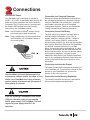
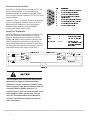
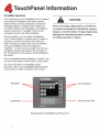
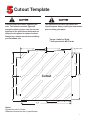
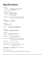
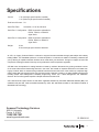
1
1
Installation
Unpacking
Carefully remove all equipment from the packing
cartons and inspect all parts for damage in
shipment. Check packing cartons for all items
shown on the packing list. Keep the cartons and
packing materials for future shipment.
If there is equipment damage due to shipment,
report the damage to the carrier who delivered the
equipment. Note: The Interstate Commerce
Commission has a time limit on reporting concealed
damage.
Safety Considerations
This equipment is suitable for Class I, Division 2,
Groups (A,B,C,D) or non-hazardous locations only.
EXPLOSION HAZARD. SUBSTITUTION OF
COMPONENTS MAY IMPAIR SUITABILITY FOR
CLASS I, DIVISION 2.
Parts Checklist
Your packing carton contains one parts kit
containing:
! 1 Packet of mounting nuts and washers
! 2 Two-terminal connectors (audio output &
security keyswitch)
! 1 Three-terminal connector (24VDC power)
! 1 Four-terminal connector (fault relay)
RISQUE D'EXPLOSION. LA SUBSTITUTION DE
COMPOSANTS PUET RENDRE CE MATERIAL
INACCEPTABLE POUR LES EMPLACEMENTS
DE CLASSE I, DIVISION 2.
Mounting
Your PanelMate unit is designed for Type 4, 4X, and
12 installations when properly mounted in a
correspondingly-rated enclosure.
Proper installation and enclosure sizing is essential
to ensure long life and trouble-free operation. Your
PanelMate unit should always be mounted in a
vertical position. Flat or angled mounting positions
will severely shorten the unit's life.
EXPLOSION HAZARD. DO NOT REPLACE
COMPONENTS UNLESS POWER HAS BEEN
SWITCHED OFF OR AREA IS KNOWN TO BE
NON-HAZARDOUS.
Refer to ATS's PanelMate Installation
Guide for installation recommendations. The Guide
is available on the ATS's web site:
www.buypanelmate.com
Panel cutout dimensions and stud torque limits are
shown on the reverse side of this Express Setup
sheet.
Note: Stud nuts must be tightened enough to
obtain a proper seal, but not over-tightened
to the point where the threads are stripped
or the gasket is rendered useless. Always
use a torque wrench when installing your
PanelMate unit.
2
RISQUE D'EXPLOSION. COUPER LE COURANT
OU S'ASSURER QUE L'EMPLACEMENT ES
DESIGNE NON DANGEREUX AVANT DE
REPLACER LE COMPOSANTS.
2
Connections
Connect DC Power
Connection to a Personal Computer
Your PanelMate unit is designed to operate at
24VDC -15%/+20%. A removable three-position DC
power connector attaches to the unit's connector
receptacle. The DC input common (-terminal) and
the chassis GND terminal are both internally
connected to the PanelMate chassis.
Executive firmware and PanelMate configurations
are uploaded/downloaded to a personal computer
using the PanelMate unit's serial port. A transfer
serial cable is provided with your PanelMate
Configuration software. Refer to your PanelMate
Getting Started Manual for more information.
2
Note: Use #18 AWG (0.82mm ) copper wire for
power and ground lead connections.
Note: Power conditioning may be required when
the PanelMate unit is installed in areas of
poor power quality.
GND
_
+
Connection to the Fault Relay
The fault relay may be wired in normally open or
normally closed configuration. It is a Form C
contact, rated for 2 amps at 120VAC, 2 amps at
230VAC, and 2 amps at 28VDC resistive load.
During normal operation, the fault relay will energize
after entering Run Mode. Whenever the PanelMate
unit detects a communication error or system
failure, the fault relay will be de-energized. It is also
possible to de-energize the fault relay whenever an
alarm condition occurs. You can set the fault relay to
de-energize on alarms by using the System
Parameters Table. Refer to the System Parameters
topic in the Configuration Software Online Help and
in the Configuration Editor User's Guide for more
information.
Connection to the Audio Output
Your PanelMate unit could be damaged if it is
connected to voltages outside the range of 18 to
30VDC. Your PanelMate unit is fully protected
against polarity reversal and will not operate if
input polarity is reversed.
The Audio Feedback Kit is an optional accessory to
your PanelMate unit. To connect the external 8 Ohm
speaker to your PanelMate unit, connect the
speaker to the audio connector.
Connection to the Security Keyswitch
The Security Keyswitch connection is provided for
external security/password applications.
If you are replacing a PanelMate Power Series
1500 unit, check the rating of your existing
24VDC power supply. The PanelMate 1700 unit
requires a power supply rated for 1.5A
operation.
3
3
Connection to Serial Ports
Serial Port 1 may be used for a printer, for PLC (or
Host) communications, or for connection to a
personal computer for upload or download. Serial
Port 2 may be used for a printer or, for PLC (or Host)
communications.
1
2
3
4
Selection of Port 1 for a Serial Printer must be done
with the Configuration Software. Refer to the PLC
Name and Port Table topic in the Configuration
Software Online Help and in the PanelMate
Configuration Editor User's Guide.
5
Pin
6
7
8
9
Description
1
2
3
4
5
6
7
8
9
RS422 Transmit Data (+) (Output)
RS232 Receive Data (Input)
RS232 Transmit Data (Output)
RS422 Receive Data (+) (Input)
Signal Ground
RS422 Transmit Data (-) (Output)
RS232 Request to Send (Output)
RS232 Clear to Send (Input)
RS422 Receive Data (-)
Serial Port Termination
Your PanelMate unit is sent without termination. For
serial port termination switch locations, refer to
Figure A. Recommended termination for RS232,
DH485 and RS422 communication is shown in the
table. For setting the termination on Serial Port 1,
use the termination switch on the left of Serial Port 1.
For setting the termination on Serial Port 2, use the
termination switch to the right of Serial Port 2.
KYSW
W
W
W
120
SERIAL PORT 1
AC
SERIAL PORT 2
120
1 2
NONE
Termination
1
4
2&3
W
W
W
120
None (factory Setting)
120 Ohm AC coupled
Refer to your PLC
Communications Driver
Manual for termination
information
AC
N/C
120
220
+ -
RS232
DH485
RS422/RS485
3 4
220
NONE
/RS232
1 2
24V
Communication Position
AUDIO
3 4
/RS232
FAULT RELAY
Figure A
Your PanelMate unit is equipped with isolated
serial ports for improved communications
reliability. If you are replacing a 120VAC Power
Series unit or a Power Series 1500 unit, and are
using an RS422 or RS485 cable for PLC
communications, you may need to install a new
cable equipped with a ground wire. Consult
your PLC Communications Driver Manual or
contact Cutler-Hammer Support Services for
more information.
4
4
Tests & Adjustments
PanelMate Diagnostic Tests
Display System Configuration Information
When power is applied to your PanelMate unit, the
unit will display a listing of internal diagnostic
checks as they are executed. After completing its
internal diagnostic checks, the unit will display the
Offline Mode Menu. This menu displays five
selections described below:
This selection displays your PanelMate unit's
current configuration. Your PanelMate unit is
shipped with a demonstration PanelMate
configuration. Once you have downloaded a new
configuration, this information will be updated to
reflect the new configuration information.
Enter Run Mode
Enter
Enter
Display
Execute
Serial
Network
System/
Diagnostics
Transfer
Transfer
Config.
Mode
Mode
Information
Enter
Run
Mode
Execute Diagnostics
This template allows you to perform a series of
tests:
!
Set Date and Time
!
Display test
!
Keypad test
!
Tone, relay and battery test
!
System status
Run Mode allows you to display the configuration
downloaded to the PanelMate unit and
communicate to the PLC (or Host) of your choice. If
a new configuration has not been downloaded, the
unit will display the demonstration configuration. For
more information on Run Mode, refer to your
PanelMate Getting Started Manual.
For information on performing these tests, refer to
your PanelMate Getting Started Manual.
Enter Serial Transfer Mode
To download, upload or read system information
over a serial port, your PanelMate unit must be in
Serial Transfer Mode. For more information on
downloading and uploading PanelMate
configurations, refer to your PanelMate Getting
Started Manual.
Enter Network Transfer Mode
Network transfer mode is used to read system
information over a remote network or remotely place
your PanelMate unit into Run Mode. For more
information, refer to your PanelMate Transfer Utility
User's Manual.
5
5
6
6
Cutout Template
Care should be taken when tightening the
nuts. The fasteners must be tightened
enough to obtain a proper seal, but not over
tightened to the point where the threads are
stripped or the gasket is rendered useless.
Always use a torque wrench when installing
your PanelMate unit.
The reproduction process may distort this
cutout template. Always check your dimensions
prior to cutting your panel.
Torque Limits for Studs
7 inch-pounds for #8-32 nuts
5.70
5.70
(144.78)
(144.78)
4.00
4.00
(101.6)
.201 DIA. HOLE
(5.11)
(101.6)
5.20
5.00
(132.1)
(127.0)
4.00
(101.6)
10.00
Cutout
(254.0)
4.00
(101.6)
5.20
(132.1)
5.50
11.00
(139.7)
(279.4)
Notes:
Dimensions are in inches.
Millimeter dimensions are in parentheses.
7
7
Specifications
Temperature
Operating:
0 to 50 degree C (grayscale & TFT color)
0 to 40 degree C (dual-scan color)
Non-Operating: -20 to 60 degree C
Humidity (non-condensing)
Operating:
20% - 80% (grayscale)
20% - 90% (color)
Non-Operating: 20% - 90% (grayscale)
20% - 95% (color)
Installation Rating: Type 4, Type 4X, or Type 12, when properly
mounted in a correspondingly-rated enclosure
Vibration
Operating:
1g at 10-500Hz
Non-Operating 1g at 10-500Hz
Shock
Operating:
30g
Non-Operating: 30g
Pollution:
Pollution Degree 1 - Rated for exposure to
dry or non-conductive pollutants only
Altitude
Operating:
10,000 feet above sea level
Non-Operating: 40,000 feet above sea level
ESD Immunity
Air:
IEC 1000-4-2, Level 4 (+/- 15kV)
Contact:
IEC 1000-4-2, Level 4 (+/- 8kV)
Radiated Immunity: IEC 1000-4-3 (10V/m) 27mHz to
1GHz 80% AM modulation
Conducted Immunity: IEC 1000-4-6 10V from 150kHz to 80mHZ,
80% AM modulation with 1kHz sine wave
Surge Immunity:
IEC 1000 - 4-5 500V
Radiated/Conductive: CISPR 22, Class A Emission
Electrical Fast Transient: IEC 1000-4-4, Level 3 (2kV) on power
lines (1kV) on I/O lines
Line Frequency Magnetic IEC 1000-4-8 Level 3, 30A/m at 50Hz
Field Immunity:
and 60Hz
9ROWDJH9'&
3RZHU:ZLWKKLJKVSHHGLQWHUIDFHLQVWDOOHG:ZLWKRXWKLJKVSHHGLQWHUIDFHLQVWDOOHG
8
8
Specifications
Current:
1.3A (with high speed interface installed)
1.1A (without high speed interface installed)
Peak Inrush Current: 5A
Serial Port Rate:
Selectable; 110 to 38,400 baud
Serial Port 1 Configuration: DB9S connection selectable for
RS232, RS422, or RS485-2
signal levels
Serial Port 2 Configuration: DB9S connection selectable for
RS232, RS422, or RS485-2
signal levels
Weight:
8 Lbs
9 Lbs with high speed interface attached
At ATS, our Legacy Products Division continues to support factories worldwide through partnerships with industry
leading OEM’s. This PanelMate product is our latest acquisition. It continues our tradition of assisting customers like
you by allowing for capital investment decisions to be made within your timeframe. Through our support of end-of-life
components, existing production lines stay running without the need for expensive upgrades.
ATS didn't earn its reputation for making factories run better by accident. We earned it by proving ourselves in some
of the most advanced and demanding factories in the world. Our breadth of expertise stretches much farther than
Legacy Products. With our award winning Industrial Parts Services we offer some of the world’s top companies high
quality repairs that look and perform like new. We also provide customers a variety of on-site Industrial Parts Services
including Repair Parts Management, Reliability Engineering, Power Tool / Asset Management and Calibration
Services. No one offers greater expertise in Repair Parts Services than ATS.
ATS’ state-of-the-art repair centers are ISO 9001 registered assessed by the British Standards Institute (BSI). Our
calibration labs are ISO 17025 accredited assessed by A2LA with standards traceable to the National Institute of
Standards and Technology.
Avanced Technology Services
8201 N University
Peoria, IL 61615
1.800.328.7287
www.buypanelmate.com
9
01-00414-04
9