1
ADM-XRC SDK 4.9.3 User Guide (Win32) - PLXDSSM - a practical example
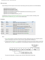
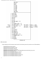
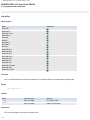
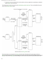
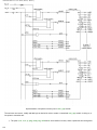
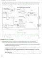
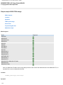
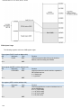
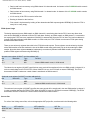
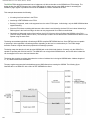
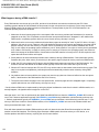
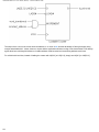
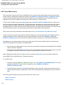
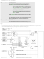
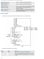
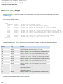
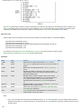
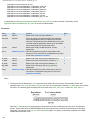
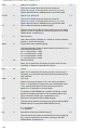
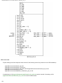
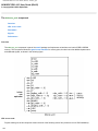
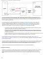
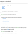
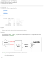
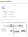
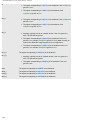
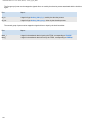
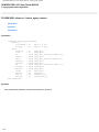
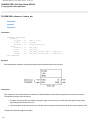
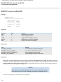
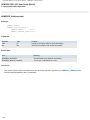
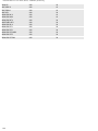
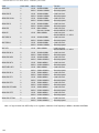
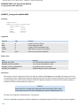
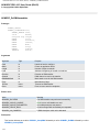
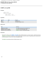
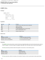
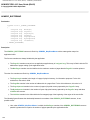
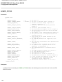
As indicated in the state diagram,
●
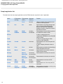
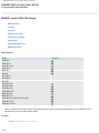
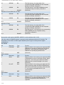
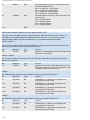
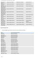
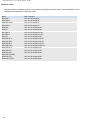
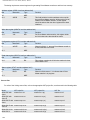
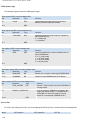
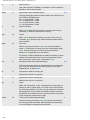
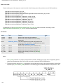
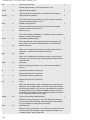
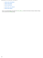
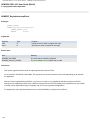
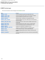
lbterm_o_l, lbterm_oe_l, ld_oe_l, lready_o_l, lready_oe_l, stopping and write are generated Mealy-style.
●
decode, idle and transfer are generated Moore-style.
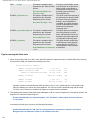
A couple of points should be noted about this implementation:
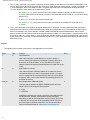
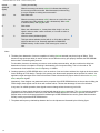
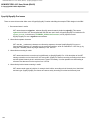
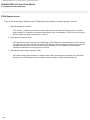
1. In the transition from XFER to IDLE, lready_oe_l remains asserted while lready_o_l and lbterm_o_l are deasserted. This ensures that
LREADY# and LBTERM# are driven high for one cycle at the end of each transfer.
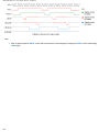
2. For convenience, the stop signal need only be pulsed for a single clock cycle, even when the user application has not yet asserted ready. The
state machine remembers that stop has been asserted via the stopping signal that is internal to the machine.
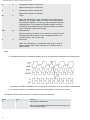
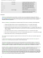
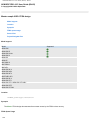
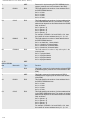
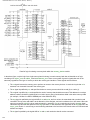
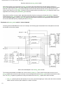
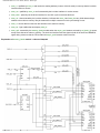
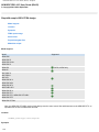
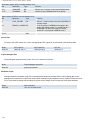
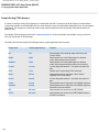
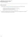
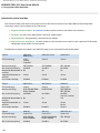
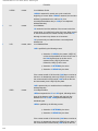
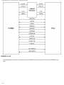
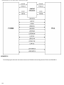
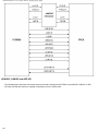
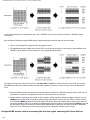
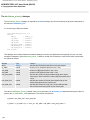
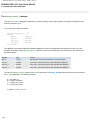
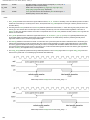
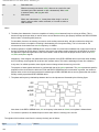
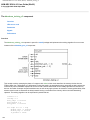
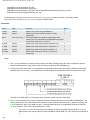
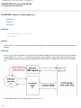
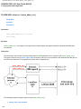
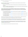
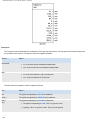
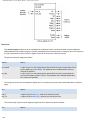
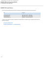
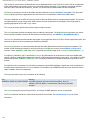
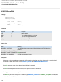
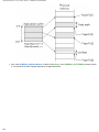
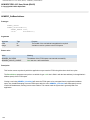
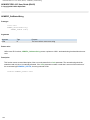
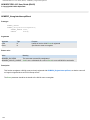
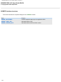
PLXDSSM timing diagrams
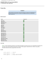
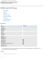
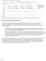
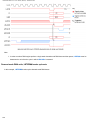
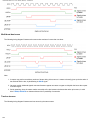
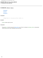
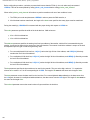
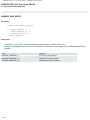
Here, a read and a write are shown. In the case of the write, ready is used to insert two extra wait cycles:
261