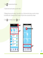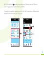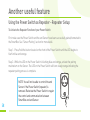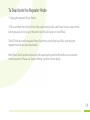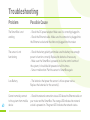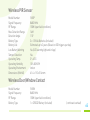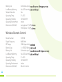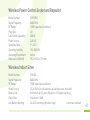
1
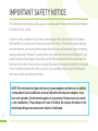
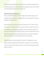
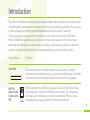
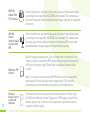
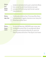
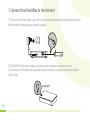
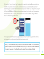
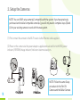
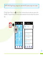
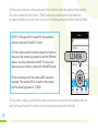
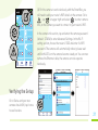
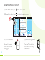
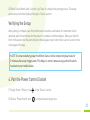
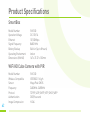
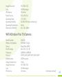
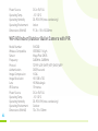
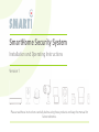
SmartHome Security System
Installation and Operating Instructions
Version 1
Please read these instructions carefully before using these products and keep the manual for
future reference.
Contents
2
Safety Notices ..............................................................................................4
System Components.....................................................................................7
Introduction....................................................................................................9
Using the Power Switch sensor as a signal repeater...............................14
Getting Started............................................................................................15
Download the Android version of the Smart-i Protect App........................15
Download the iOS version of the Smart-i Protect App................................15
1. Connect the SmartBox to the Internet..................................................16
2. Setup the Cameras.................................................................................18
3. Pairing the PIR Sensor............................................................................22
4. Pairing the Power On/Off Switch...........................................................23
5. Pairing the Door/Window Sensor..........................................................25
6. Pairing the Indoor Siren.........................................................................27
7. Pairing the Remote Key..........................................................................28
How to install the Cameras.......................................................................30
Installing the Cube Camera........................................................................30
Installing the Pan Tilt Camera...................................................................31
Installing the Indoor/Outdoor Bullet Camera...........................................32
How to install the Accessories..................................................................33
1. Installing the PIR Sensor........................................................................33
2. Installing the Door/Window Contact.....................................................34
3. Installing the Siren..................................................................................36
App Operation.............................................................................................37
Status Page Diagram..................................................................................37
1. Status Indicator/Edit...............................................................................38
2. Scenario...................................................................................................40
3. Event List.................................................................................................47
4. Settings....................................................................................................48
Another Useful Feature.............................................................................58
Troubleshooting..........................................................................................60
Product Specifications..................................................................... ..........62
3
IMPORTANT SAFETY NOTICE
This information can help you safely use your security system. Follow and retain all information
included with your system.
Customer safety is important. Our products are developed to be safe and effective. However,
the SmartBox, Accessories and Cameras are electronic devices. Power leads, power adapters,
and other features can create potential safety risks that can result in physical injury or property
damage, especially if misused. To reduce these risks, follow the instructions included with your
product, observe all warnings on the product and in the operating instructions, and review the
information included in this document carefully. By carefully following the information contained
in this document and provided with your product, you can help protect yourself from hazards
and create a safer operating environment.
NOTE: This information includes references to power adapters and batteries. In addition,
some products (such as additional cameras) ship with external power adapters. If you
have such a product, this information applies to your product. Some accessories contain
a coin-sized battery - Please keep out of reach of children. Do not place the battery in the
mouth as by doing so can cause severe injuries if swallowed.
4
The cords and cables supplied with the system can present a potential strangulation hazard if
the child plays with the cords or cables and it becomes wrapped around the neck. Please make
sure cords and cables are placed out of reach of the child.
Conditions that require immediate action
Products can become damaged due to misuse or neglect. Some product damage is serious
enough that the product should not be used again until it has been inspected and, if necessary,
repaired by an authorised servicer.
As with any electronic device, pay close attention to the product when it is turned on. On very
rare occasions, you might notice an odour or see a puff of smoke or sparks from your product,
or you might hear sounds like popping, crackling or hissing. These conditions might merely
mean that an internal electronic component has failed in a safe and controlled manner, or they
might indicate a potential safety issue. However, do not take risks or attempt to diagnose the
situation yourself. Contact our Customer Support Team for further guidance.
Frequently inspect your security system and its components for damage/wear or signs of
danger. If you have any questions about the condition of a component, do not use the product.
Contact our Customer Support Team for instructions on how to inspect the product and have it
repaired, if necessary.
5
In the unlikely event that you notice any of the following conditions, or if you have any safety
concerns with your product, stop using the product and unplug it from the power source and
telecommunication lines until you can speak to the Customer Support Team on 0871 222 1430
for further guidance.
POSSIBLE HAZARDS
• Power leads, plugs, power adaptors, extension leads, surge protectors, or power supplies that
are cracked, broken or damaged.
• Signs of overheating, smoke, sparks or fire.
• Damage to a battery (such as cracks, dents, or creases), discharge from a battery or a buildup
of foreign substances on the battery.
• A cracking, hissing or popping sound, or strong odour that comes from the product.
• Signs that liquid has been spilled or an object has fallen onto the SmartBox/Accessories/
Camera and the power lead or power adapter.
• The SmartBox/Accessories/Camera power cord or power adapter has been exposed to water.
• The product has been dropped or damaged in any way.
• The product does not operate normally when you follow the operating instructions.
WARNING: This product is not designed or approved for use on power lines other than 100240VAC, 50Hz or 60Hz, single phase.
Attempting to use this product on non-approved power lines may have hazardous
consequences.
6
System Components
DO NOT REMOVE THE INSULATING PLASTIC on the sensors. It will activate the pairing process.
Please follow the sections below for easy installation. If you have already removed the insulating
plastic tab, please refer to the section "If you need to pair the sensor again:" to add sensor(s) to
the system.
SmartBox SHG100
Adaptor DC 12V/1A
WiFi HD
Indoor Cube
Camera with
PIR SHC100
Bracket
Ethernet Cable 2m
Adaptor DC 5V/1.5A
Ethernet Cable 2m
WiFi HD
Indoor Pan
Tilt Camera
SHC200
Adaptor DC 5V/1.5A
Camera Antenna
WiFi HD
Indoor/Outdoor
Bullet Camera
with PIR
SHC300
7
Bracket Camera Antenna Adaptor DC 5V/1.5A Wall Fixing Pack USB to RJ45 Lead
Wireless PIR
Sensor
SHDP
3x AA Batteries 1.5V
Wireless
Power Control
Socket and
Repeater
Sticky Pad Set
No Accessories
SHP100R
Wireless Door/
Window
Contact
SHDM
1x CR2032 Battery
Sticky Pad Set
Adaptor DC 5V/1A
Bracket
Wireless
Indoor Siren
SHS100
Wireless
Remote
Control
SHR100
8
1x CR2032 Battery
Wall Mount Set
Bracket
Introduction
The Smart-i SmartHome Security System is an expendable and extendable security system that
combines power management to make your life more secure and energy efficient. You can scale
up the coverage at anytime by implementing additional sensor(s) and/or camera(s).
You can easily access the system from anywhere in the world via the Internet. The Smart-i
Protect iOS/Android app allows you to view/record video, turn power switch on/off, activate/
deactivate siren manually or automatically. You can also create various scenarios to allow the
system to automatically respond to the situation even when you are not at home/office.
Product Name
Function
SmartBox
The central control of the SmartHome Security System. It provides
communication for remote access, sensors and mobile devices. SmartBox
can send out push notification and Email when a sensor is triggered.
WiFi HD
Indoor Cube
Camera with
PIR
Offers day/night on-site/remote live-view (visual verification) and video
recording and storage (MicroSD 32GB, not included). The camera also
has dual-layer motion detection consist of hardware PIR sensor and
embedded video image analyser for maximum protection.
9
WiFi HD
Indoor Pan
Tilt Camera
Offers day/night on-site/remote live-view (visual verification) and video
recording and storage (MicroSD 32GB, not included). The camera also
has motion detection with embedded video image analyser for maximum
protection.
WiFi HD
Indoor/
Outdoor Bullet
Camera with
Offers day/night on-site/remote live-view (visual verification) and video
recording and storage (MicroSD 32GB, not included). The camera also
has dual-layer motion detection consist of hardware PIR sensor and
embedded video image analyser for maximum protection.
PIR
Wireless PIR
Sensor
Built for larger area detection, such as living room or entrance. Once
it detects motion, the motion PIR can alert the system and activate On/
Off Switch (turning on light), Siren (alert sound) and Camera (view/
record).
Note: To conserve battery power, the PIR Sensor will be temporarily
deactivated for 2 minutes after every trigger event. This controls
unnecessary push notifications received on your mobile device.
10
Wireless
Power Control
Socket and
Repeater
The Power Control Socket can be controlled via Smart-i Protect app
(On/Off), Door/Window Sensor (trigger on), PIR (trigger on) and Panic
Remote (preset on). It can also act as repeater to extend the service
range for another device.
Wireless
Door/
Window
Contact
Installed on to door/window. After the system is armed the Door/Window
Sensor can alert the system the door/window has been opened
and activate On/Off Switch (turning on light), Siren (alert sound) and
Camera (view/record).
Wireless
Indoor Siren
The Siren can be controlled via Smart-i Protect App and Panic Remote
(activate/deactivate) or triggered by other devices such as Camera, Door/
Window Sensor and Motion Sensor.
Wireless
Remote
Control
You can use the Remote Key to ARM/DISARM system, activate camera
recording function and set off Siren. You can predefine which different
sensor(s) you want to work with the Remote Key. The control of the
Remote Key connects with the Smart-i Protect App One-Touch-Scenario.
11
The diagram below shows the suggested location(s) for SmartHome Security System. Use this
as a guide for your installation. The system is extendable and expandable with additional
Power Control
Indoor/Outdoor
Camera
Remote Control
Adaptor DC 5V/1.5A
Battery CR2032
PIR Sensor
SmartBox
Battery AA 1.5V x 3
12
Adaptor DC 12V/1A
compatible Wireless Cameras, Motion Sensors, Door/Window Contact sensor, Siren and other
sensors for greater protection.
Indoor Pan Tilt
Camera
Indoor Siren
Adaptor DC 5V/1.5A
Adaptor DC
5V/1A
OR
Battery AA 1.5V x 4
Door/Window
Sensor
Battery
CR2032
Indoor Cube
Camera
Adaptor DC 5V/1.5A
13
Using the Power Control Socket as a Signal Repeater
In some cases, pre-existing environmental factors may affect the performance of the wireless
communication between the SmartBox and sensors, such as:
- Numbers of walls between the SmartBox and the Sensor(s)
- Materials of the building structure
- Interference from unknown source
When encountering such situation, you can use the Power Control Socket
as signal repeater to improve the wireless transmission service range.
Please note that at any given time, after successful setup, the Power
Control Socket repeater function can extend the communication for one
single sensor, such as Motion Sensor, Power On/Off Switch, Siren and
Door/Window Sensor. The Power Switch will still obtain its original On/Off
function after the repeater function has been activated.
14
To establish the repeater function, additional between the Power Control
Socket (repeater) and the end Sensor will be required. For best
performance, the Power Control Socket (repeater) should have direct
sight with the end sensor, without any wall/obstructive objects in between.
Getting Started
The sensor(s) require sufficient battery power enable a successful pairing process and normal
operation afterwords. If you cannot pair the sensor(s) to the SmartBox or operate control
command, please first replace the battery supplied with a new one to resolve the issue.
Download the Android version of the Smart-i Protect App
Please go to the Google Play to search for 'Smart-i Protect' and install the app to your mobile
device.
Download the iOS version of the Smart-i Protect App
Please go to the Apple App Store to search for 'Smart-i Protect' and install the app to your mobile
device.
15
1. Connect the SmartBox to the Internet
(1) First connect the SmartBox to your Wi-Fi router via the Ethernet cable supplied, then power on
the SmartBox by using the power adaptor supplied .
(2) The RED LED indicator will light up and beep twice to indicate successful power up.
Seconds later the SmartBox will again beep twice to indicate it is ready for setup via the 'Smart-i
Protect' App.
Steady RED
16
(3) Launch the 'Smart-i Protect' App. The App will first search for the SmartBox connected to the
home Wi-Fi router and retrieve the DID automatically. Please assign the SmartBox with your
preferred System Name and enter the Default Security Code '123456', tap to complete the setup. If
the SmartBox DID/Security Code cannot be retrieved, please check to make sure it is powered on
and the Ethernet cable is securely connected to the Wi-Fi router. Also make sure your mobile
device is connected to your WiFi router.
The newly added SmartBox will now appear and you can tap it to enter the system and continue
with setup for camera(s), sensor(s), switch(es) and remote control.
NOTE: (1) The SmartBox should be powered on and connected to the Wi-Fi router at all times.
(2) Should you need to enter the SmartBox DID/Security Code manually, the DID information
is located at the bottom of the SmartBox and the default Security Code is '123456'.
17
2. Setup the Cameras
NOTE: You can ONLY setup camera(s) compatible with the system. If you have previously
purchased and installed compatible camera(s), you will only need to complete steps (3) and
(4) for your existing camera to work with the new system.
(1) First connect the camera to the Wi-Fi router via the Ethernet cable supplied.
(2) Power on the camera via the power adaptor supplied and wait until for both RED (power
indicator) /GREEN (linkage indicator) indicators become steady on.
NOTE: Follow the same Setup
procedure for the Pan Tilt
Camera and the Bullet Camera
18
NOTE: DO NOT begin the App setup process until both LEDs become steady on the camera.
(3) Using 'Smart-i Protect', tap
in the 'Status' section and choose to add a new camera to the
SmartBox. The app will now search for the camera connected to the router and pull in the camera
DID.
Status
Select Device
Gi7-351
GO1-D-038
on Table
Room
Siren
PowerSwitch
Hallway
Book Room
Door Sensor
PIR
Back Door
Lounge
Camera
Siren
Remote Key
Door Sensor
Motion Sensor
Remote Key
Status
Scenario
Power Switch
Event
Setting
Status
Scenario
Event
Setting
19
(4) Please now name your camera and specify the location of where the camera will be installed.
The camera default Security Code is '123456' (previously installed camera may have been
assigned with different security code). Tap 'Save' to complete pairing the camera to the SmartBox.
NOTE: (1) The app will first search for the available
camera connected to the Wi-Fi router.
(2) If the camera cannot be found, please first check to
make sure the camera is powered on and the Ethernet
cable is securely connected to the Wi-Fi router, also
make sure your mobile is connected to the WiFi router.
123456
(3) You can always enter the camera DID/ password
manually. The camera DID is located on the camera
and the default password is '123456'.
Status
Scenario
Event
Setting
(5) If you prefer using your own Ethernet cable, you can now swap out the cable supplied with your
own (Cat 5e patch cable). For wireless connection/operation please follow Step (6).
20
Status
Gi7-351
GO1-D-038
on Table
Room
Siren
PowerSwitch
Hallway
Book Room
Door Sensor
PIR
Back Door
Lounge
Remote Key
Status
Scenario
Event
Setting
(6) For the camera to work wirelessly with the SmartBox, you
will need to add your router’s WiFi details to the camera: Go to
,tap
on upper right and select
to enter camera
info, on the camera you want to connect to your router’s WiFi.
In the camera info section, tap and enter the camera password
(default: 123456) to enter Advanced Settings. In the Wi-Fi
setting section, choose the router’s SSID and enter it’s WiFi
password. The camera will automatically reboot, please wait
until both LED's on the camera become steady on. You can now
remove the Ethernet cable, the camera can now operate
wirelessly.
XXXX-XXXXXX-XXXXX
Verifying the Setup
Go to Status and your new
camera should ON, tap it once
to see live view.
21
3. Pair the Motion Sensor
(1) Using 'Smart-i Protect', tap
in the 'Status' section.
(2) Choose 'Motion Sensor' and
to initiate the pairing process.
Select Device
Status
Gi7-351
GO1-D-038
on Table
Room
Siren
PowerSwitch
Hallway
Book Room
Door Sensor
PIR
Back Door
Lounge
Step 1 of 3
Please tap “Pair” to begin pairing
process
Camera
Siren
Remote Key
Door Sensor
Motion Sensor
Remote Key
Status
22
Scenario
Power Switch
Event
Setting
Status
Scenario
Event
Setting
Status
Scenario
Event
Setting
(3A) Auto Pairing Method
(3B) Manual Pairing Method
Remove the insulating
plastic tab to start the
pairing signal.
Press the 'Pairing' button
located inside the battery
compartment.
(4) Enter 'Device Name' and 'Location', tap 'Save' to complete the pairing process. The newly
paired sensor will now display in the App's 'Status' section.
Verifying the Setup
After pairing is complete, face the motion sensor towards a wall where no movement can be
detected, wait for few minutes for the sensor to complete condition analysis. Wave your hand in
front of the sensor and the alert indicator should appear next to the motion sensor section on the
status page of the App.
NOTE: To conserve battery power, the Motion Sensor will be temporarily deactivate for
2 minutes after every trigger event. This helps to control unnecessary push notifications
received on your mobile device.
4. Pair the Power Control Socket
(1) Using 'Smart-i Protect', tap
in the 'Status' section.
(2) Choose 'Power Switch' and
to initiate the pairing process.
23
Select Device
Status
Gi7-351
GO1-D-038
on Table
Room
Siren
PowerSwitch
Hallway
Book Room
Door Sensor
PIR
Back Door
Lounge
Step 1 of 3
Please tap “Pair” to begin pairing
process
Camera
Siren
Remote Key
Door Sensor
Motion Sensor
Power Switch
Remote Key
Status
24
Scenario
Power Switch
Event
Setting
Status
Scenario
Event
Setting
Status
Scenario
Event
Setting
(3A) Auto Pairing Method
(3B) Manual Pairing Method
Plug the power switch into a
socket. The LED will flash,
indicating the power switch
is sending out the pairing
signal. When the power
switch is successfully
paired, it will appear on the
Status page of the App.
Press and hold the button located in the
front of the Power Switch until the blue
LED begins flashing.
(4) Enter 'Device Name' and 'Location', tap 'Save' to complete the pairing process. The newly
paired power control socket will now display in the App's 'Status' section.
Verifying the Setup
After pairing is complete, plug the power switch into an electrical socket and connect a light or
lamp to the switch. If the light fixture or any other device has its own On/Off switch, please
keep it in the 'On' position. Tap the power switch icon on the status page to turn the light on and off.
NOTE: The power switch can also double as 'Repeater'. This function is for advanced users.
For details please refer to Power Switch/Repeater section of this manual.
5. Pair the Door/Window Sensor
(1) Using 'Smart-i Protect', tap
in the 'Status' section.
(2) Choose 'Door Sensor' and
to initiate the pairing process.
25
Select Device
Status
Gi7-351
GO1-D-038
on Table
Room
Siren
PowerSwitch
Hallway
Book Room
Door Sensor
PIR
Back Door
Lounge
Step 1 of 3
Please tap “Pair” to begin pairing
process
Camera
Siren
Remote Key
Door Sensor
Motion Sensor
Remote Key
Status
Scenario
Power Switch
Event
Setting
Status
Scenario
Event
Setting
Status
Scenario
Event
Setting
(3A) Auto Pairing Method
(3B) Manual Pairing Method
Remove the insulating
plastic tab to start the
pairing signal.
Remove the battery cover and
battery and then replace both.
(4) Enter 'Device Name' and 'Location', tap 'Save' to complete the pairing process. The newly
paired sensor will now display in the App's 'Status' section.
Verifying the Setup
26
After pairing is complete, separate the two parts of the sensor and the alert indicator should
appear next to the door/window sensor section on the status page of the App.
6. Pair the Indoor Siren
(1) Using 'Smart-i Protect', tap
(2) Choose 'Siren' and
in the 'Status' section.
to initiate the pairing process.
Select Device
Status
Gi7-351
GO1-D-038
on Table
Room
Siren
PowerSwitch
Hallway
Book Room
Door Sensor
PIR
Back Door
Lounge
Step 1 of 3
Please tap “Pair” to begin pairing
process
Camera
Siren
Siren
Remote Key
Door Sensor
Motion Sensor
Remote Key
Status
Scenario
Power Switch
Event
Setting
Status
Scenario
Event
Setting
Status
Scenario
Event
Setting
(3A) Auto Pairing Method
(3B) Manual Pairing Method
For the Indoor Siren to send out pairing signal,
power using the adaptor or batteries supplied.
Press the 'Pairing' button located
inside the battery compartment.
Please make sure the Indoor Siren
has batteries inserted or is
connected to an electrical socket
via the adaptor supplied.
27
(4) Enter 'Device Name' and 'Location', tap 'Save' to complete the pairing process. The newly
paired siren will now display in the App's 'Status' section.
Verifying the Setup
From the 'Status' section, tap the Siren icon and turn the Siren's alert sound On and Off.
7. Pair the Remote Key
(1) Using 'Smart-i Protect', tap
in the 'Status' section.
(2) Choose 'Remote key'' and
to initiate the pairing process.
Select Device
Status
Gi7-351
GO1-D-038
on Table
Room
Siren
PowerSwitch
Hallway
Book Room
Door Sensor
PIR
Back Door
Lounge
Step 1 of 3
Please tap “Pair” to begin pairing
process
Camera
Siren
Remote
KeyKey
Remote
Door Sensor
Motion Sensor
Remote Key
28
Status
Scenario
Power Switch
Event
Setting
Status
Scenario
Event
Setting
Status
Scenario
Event
Setting
(3A) Auto Pairing Method
(3B) Manual Pairing Method
Remove the insulating
plastic tab to start the
pairing signal.
Press and hold the 'Camera'
button on the front of the
Remote Key until the blue
LED begins flashing.
Verifying the Setup
Press the 'Disarm' button
disarmed.
the SmartBox will beep once indicating the system has been
Press the 'Arm' button
the SmartBox will beep twice and a 'Countdown' pop-up will appear,
select 'Disarm' to deactivate system arming.
29
How to install the Cameras
SAFETY AND INSTALLATION TIPS
Do not attempt to open the units with the power adaptor plug connected to avoid any
risk of personal injury. When installing CCTV camera(s), always follow manufacturer's advice
when using power tools, steps, ladders, etc. and wear suitable protective equipment (e.g. safety
goggles) when drilling holes. Before drilling holes through walls, check for hidden electricity
cables and water pipes. The use of cable/pipe detector is advisable.
Both the Cube and Pan Tilt Cameras are designed for indoor use only, please do not install them
outdoors. The Bullet Camera can be used both indoors and outdoors. To prevent a fire or
electrical shock hazard, do not attempt to open the housing while the unit is exposed to water or
wet conditions. There are no user serviceable parts inside. Refer servicing to qualified service
personnel. Avoid pointing the camera(s) directly at the sun or any moving objects that might
unnecessarily cause the camera to record.
Installing the Cube Camera
(1) Secure the camera bracket on a level surface or wall mount using screws provided.
30
(2) Mount the camera onto camera bracket . Adjust the viewing angle and fix the camera tightly.
Installing the Pan Tilt Camera
(1) Place the camera on a level surface away from obstacles or
potential hazards.
(2) Attach the Antenna and plug the power supply into the back
of the camera.
31
Installing the Indoor/Outdoor Bullet Camera
(1) Secure the camera stand on a level surface or wall mount using screws provided.
(2) Attach the Antenna and plug the power supply into the back of the camera.
(3) Mount the camera on to camera bracket. Adjust the viewing angle and fix the camera tightly.
32
How to install the Accessories
Installing the PIR Sensor
Please read the following items before installation to ensure maximum coverage of a monitored
area.
(1) The PIR Sensor is most effective in areas such as hallways and
entry points where intruders may likely passing through.
16
(2) The PIR Sensor can monitor movement up to 16 metres away, with
110 degrees detection angle. Make sure the PIR Sensor is angled
facing towards an area with the least obstructions for best coverage.
m
etr
es
110 degrees detection angle
(3) It is recommanded to place the Motion Sensor in the corner of the
room and between 2-2.5 metres from the floor.
Use the double-sided tape to fix the motion sensor, or use the wall
mount screws to fix the device or supplied bracket onto the wall.
2 - 2.5 metres
33
C
The thick double-sided tapes are
B
The thin double-sided tapes are
for corner install use.
Mounting Option A
Mounting Option B/C
Installing the Door/Window Contact
Mounting Option A - Double-Sided Tape
34
(1) Apply the double-sided tape to the back of each part of the
Door/Window sensor.
(2) Select a location on the door/window. The large piece of the sensor should be fixed on the
immovable frame of the door/window.
Align the small piece to the large one. Fix the small piece on the movable part of the door/window
frame.
(3) When both parts are fixed, open the door or window to test if the sensor has been correctly
installed. If you have installed the App and sensor correctly you'll receive an alert from your mobile
device.
Mounting Option B - Mounting Screws
(1) Fix the first mounting screw directly onto the door/window frame (A). Place (hang) the
larger piece on to the mounted screw, remove the battery compartment cover to fix the second
mounting screw (B).
(2) Open back cover of the small piece. Use the mounting screws to fix
the back cover on the movable part of the door/window frame (C).
Mount the sensor onto the back cover.
A
C
(3) When it is finished, open the door or window to test if the sensor has
been correctly installed. You'll receive an alert from the mobile device if
the App and sensor have been correctly installed.
B
35
Installing the Siren
It is recommended to install the siren in a highly visible location with minimum obstacles near by
for maximum visual/sound alert.
If using the A/C power option (as opposed to batteries) please select suitable installation location
within easy reach of an electrical socket. Secure to wall using bracket and fixing screws.
36
App Operation
Upon selecting the SmartBox you will enter 'Status' section. In this section you can have an
overview of all the cameras/sensors connected to the system and the real-time status of each,
also you can carry out many important functions, such as arm/part-arm/disarm system,
add/edit devices, view live-feed from cameras, control power switches, activate sirens. You can
also navigate to other sections of the App by using the navigation bar.
Status Page Diagram
SmartBox Selection Section
Tap on the SmartBox preferred to enter
Set up Status
Add Device
Status
Return
Device Icon
Status Display
arm/part-arm/
disarm
Edit
Wireless
Camera
Device Name
Front Door
Device Location
Power Switch
Bedroom
PIR
Lounge
Status
Zone
Event List
System Setting
Scenario
37
1. Status Indicator / Edit
The App displays device status
using sharp contrast icons so
you can clearly interpret and
react to the situation/event.
Door/Window Close
Status
Status
Gi7-351
GO1-D-038
on Table
Room
Siren
PowerSwitch
Hallway
Book Room
Door Sensor
PIR
Back Door
Lounge
Scenario
Status Indicator
Sensor On
Sensor Off
Sensor Triggered
Tamper Alert
Delete
Edit Icon
Event
Tap 'Edit' to enter Edit Mode and select the device. You
can alter the name and location information, for Power
Switch you can setup Auto OFF timer (only effective for
Scenario) and for Contact Sensor you can setup Entry
Delay Time so after the system is armed the contact
will not set off the system for 30 seconds.
38
ON
Power Low
Remote Key
Status
Door/Window Open
Setting
Edit Mode
Control Camera
Tap on the Camera icon for
live-view and to control
Camera/Sensor(s).
No SIM
appcam 25
11.34
Camera Control
driveway
Note: For Pan Tilt swipe left
and right to move camera.
Snapshot
Camera
Live-View
Speaker
Sensor
Control
PowerSwitch
Siren
Record
Preset View-Points
Microphone
Control Power Switch
1. Tap on the Power Switch icon to control the
selected Power Switch
On/Off
Living Room
2. Tap 'On' or 'Off' to turn Power Switch on or off
Control Siren
1. Tap on the Siren icon to control selected Siren
2. Tap 'On' or 'Off' to turn the Siren’s alert sound on
or off
Siren
Hallway
39
Control Remote
Tap on remote icon to activate in-app remote
Remote
System Arm
Camera Record
Lounge
System Disarm
Panic
See 'Scenario' section for more detail
2. Scenario
Scenario
Scenario
One-touch scenario
ARM
Camera
Panic
Motion Sensor
Living room
Sequence scenario
Wireless Camera
Front Door
40
Status
Scenario
Event
Setting
Both the 'One-touch Scenario' and the 'Sequence Scenario' are designed for your system to carry
out customised security functions after setup, such as activate single/multiple cameras and
sensors for recording and alert.
One-touch Scenario
Allowing you to conveniently activate the security function with a single touch when required. The
one-touch scenario section has three default controls and they connect with the control
buttons on the remote controller. You can customize the content of each to fit your needs. After
setup, the control buttons on the remote will carry out the same commands as the one-touch
scenarios in the App.
Scenario
ARM
Camera
Panic
41
(a) Arm/Part-Arm/Disarm:
Arm or Part-Arm preselected camera(s) and sensor(s). Select Disarm to disable system's Arm
or Part-Arm status. Only after you have armed the system you will be able to receive Email/Push
Notifications (see System Setting/Notifications Setup for detail).
You will have 30 seconds to exit the premise after initiating the Arm or Part-Arm function.
(b) Camera:
Activate selected camera(s) for sudden recording needs.
(c) Panic:
Activate selected camera(s), siren(s) and power switch(s) for emergency recording, alarm sound
and/or lighting needs.
By default, the sensors will appear in the control group list after you have paired the sensors to
the SmartBox. Please follow the next steps to edit the One-touch Scenario.
Setup the One-touch Scenario
To setup customised one-touch scenarios (Arm/Camera/Panic), please go to the Scenario
section and follow the next steps:
42
1. Tap
to activate the edit mode.
2. Tap the one-touch scenario you wish to edit.
3. Rename the one-touch scenario if you wish to do so. Check mark the items you wish to include
for Arm/Part-Arm, Camera and Panic scenario. Only the items selected will be activated.
4. Tap
to complete setup or
to exit.
Scenario Setup
Scenario
ARM
Select Device
Gi7-351
ARM1212
Camera22
Panic
Door Sensor
Back Door
Home
Study
123 Siren
Office
Home
Bedroom
Home PIR
Hallway
Home Contact
Back Door
PIR
Hallway
Gi7-351
on Table
GO1-D-038
Study
Status
Scenario
Event
Setting
Status
Scenario
Event
Setting
43
Sequence Scenario
Allowing the system to automatically react to the sudden situation and carry out other predefined
tasks. For example, once the motion sensor is activated, the camera will begin recording and the
light turns on.
To setup the sequence scenario(s), please go to the Scenario section and follow the steps
below:
1. Tap to select one of the 'initiator' (When...) from the list (example: door/window contact).
2. From the list. tap
3. You can continue (tap
or
to exit setup.
to select the 'follow-uper' (Then..., example: camera).
) to include more 'follow-uper'. Tap
to complete the setup
With the example sequence scenario, once the motion sensor (initiator) detects movement, the
camera (follow-uper) will automatically begin recording.
44
In order for scenario to function properly, please make sure the sensor(s) in the list are activated
(a). For your chosen camera you will need to check 'Record' so the camera will record video and
'View' for auto video screen popup (MicroSD card required, not supplied).
(b). Click the ' Add ' icon
to add corresponding sensor. This means when the PIR motion
sensor is triggered, these actions will also be performed.
For example, if you want the camera to record, click the ' Add ' icon and choose wireless camera
from the list (MicroSD card required, not supplied).
Scenario
Scenario
When...
Door Sensor
Back Door
ARM
Camera
Panic
Door Sensor
Back Door
Then...
PIR
Hallway
Gi7-351
on Table
Record
View
Gi7-351
on Table
Status
Scenario
Event
Setting
Status
Scenario
Event
Setting
45
How to activate/deactivate the scenario:
Go to the Scenario setup page and tap 'On' to activate the selected sequence scenario, or 'Off' to
deactivate it.
Scenario Setup
When...
Door Sensor
Back Door
Then...
Gi7-351
on Table
Status
Scenario
Record
The system will take about 10 seconds to be
fully ready to deploy the scenario application
after activating the scenario.
View
Event
Setting
NOTE: The system will not send out any Email Alert or Push Notification when Sequence
Scenario is active.
46
3. Event List
Events
Power Switch
Power Switch
Power Switch
Power Switch
All triggered events are recorded and displayed here in the 'Event' section. You will be able to
identify exactly which sensor was triggered, including the time and the date. You can also review
recorded video file by tapping on the camera trigger event.*
*Camera must have MicroSD card fitted, not supplied.
47
4. Settings
The system settings contain various options allowing you to setup/configure the system details.
The default admin password is '123456'.
Setting
123456
NOTE: Only the user who has the admin password can alter the system settings.
Please change the default password immediately and make a note for future reference.
48
IP Setup
Setup the Internet protocol settings for the system.
XXX.XXX.XXX.XX
XXX.XXX.XXX.X
XXX.XXX.XXX.XXX
49
Security Setup
Here you can alter the system's default 'Security Code' and 'Admin Password'. Also you can
enable/disable and setup the PIN Lock for the app. Once setup and enabled, you will need to
enter the PIN Lock code every time you open the App.
50
Notification Setup
Here you can turn On/Off the Email Alert and Push Notification. For the Email Alert to function
properly you will need to enter an effective email address.
Both Email/Push Notification are available for system Arm, Disarm and trigger events generated
from camera, motion sensor and door/window sensor selected in the Arm/Disarm scenario
section.
NOTE: For iOS app, if you turn off the Notification function here you and others will not be
able to receive push notifications, even you have turned on the notification function in the
notification section of the iOS system settings.
51
Schedule Setup
This is designed specifically for the power switch. After you have setup the selected power
switch(s) can turn on/off accordingly. Please follow the steps below to complete setup:
1. From the list, tap the switch you wish to setup.
2. Tap
to begin setup.
3. Check mark the days.
4. Define 'start' and 'end' time.
5. Tap
52
to complete setup or
to exit setup.
For Power Switch, you can also select Random On/Off. This is good for creating "someone is
home" scenario to deter possible intruders.
NOTE: Since the system automatically synchronises its clock with Network Time Protocol
(NTP) via the Internet therefore the Protect schedule setup will not operate normally if the
system is not connected to the Internet.
(NTP) is a networking protocol for clock synchronisation between computer systems and
servers over the Internet.
53
Firmware Updates
Here you can check to see if any new updates are available. To begin, tap on 'Download' and
if a new update is available, the popup screen will ask you if you wish to proceed, select 'Yes' and
the Smart-i Protect app will automatically download and install the new update.
NOTE: Please do not power off the SmartBox or unplug the Ethernet cable connected to it
during the update.
54
Remote Style
The 'Remote Control' mode is designed for easy operation. The control functions are the same as
the 'One-touch Scenario' and the remote controller.
Once you have activated the function, next time you start the Smart-i Protect App or go back to the
Home screen it will only display the 'Remote Control'. To deactivate, go to system setting and
deactivate the function in the 'Remote Style' section.
55
Advance Control
Here you can turn on the 'Zone' function. This function is for advanced users only. The 'Zone'
function can control camera(s) and power switch(s) and can be activated/deactivated with one
single touch. You can have up to 9 Zone controls, with each customised to fit your needs. To
activate the 'Zone' function, please follow the steps below:
1. Go to System Setting, in the 'Advanced Control' section, turn on the 'Advance Control'.
2. The 'Zone' control function will appear at the bottom of the navigation section after exiting
System Setting.
56
About
The system ID (DID), firmware and App information.
To setup the 'Zone' control, please go to 'Zone' section follow the steps below to complete the setup.
1. Tap
to begin.
2. You can personalise the Zone name.
3. Check mark the camera(s) and/or power switch(s) you wish to include for control.
4. Tap
to complete the setup or
to exit setup.
Zone Setup
Zone 1
1
Control 1
2
Control 22
Control
Select Device
Home
Study
Home
Bedroom
57
Another useful feature
Using the Power Switch as Repeater - Repeater Setup
To Activate the Repeater Function of your Power Switch
First make sure the Power Switch and the end Sensor have been successfully paired/connected to
the SmartBox. See "Sensor Pairing" section for more detail.
Step 1 - Press/hold the button located on the front of the Power Switch until the LED begins to
flash in blue and orange.
Step 2 - While the LED on the Power Switch is flashing blue and orange, activate the pairing
mechanism on the Sensor. The LED on the Power Switch will turn steady orange indicating the
repeater pairing process is complete.
NOTE: You will not be able to control the end
Sensor if the Power Switch (repeater) is
removed. Reinstate the Power Switch to regain
the control and communication between
SmartBox and end Sensor.
58
To Deactivate the Repeater Mode
1. Unplug the repeater Power Switch.
2. Press and hold the button in front of the switch and plug the switch back to the socket with the
button pressed, do not let go of the button until the LED begins to flash (Blue).
The LED indicator on the repeater Power Switch now should light up in Blue, indicating the
repeater function has been deactivated.
Both Power Switch and the end sensor will require pairing with the SmartBox to resume their
normal operation. Please see 'Sensor Pairing' section for more details.
59
Troubleshooting
60
Problem
Possible Cause
The SmartBox is not
working
- Check the DC power adapter. Make sure it is correctly plugged in.
- Check the Ethernet cable. Make sure the connector is plugged into
the Ethernet socket and the other end plugged into the router.
The sensor is not
functioning
- Check the battery polarity and make sure the battery has enough
power to function correctly. Replace the batteries if necessary.
- Make sure the SmartBox is powered on. As the control centre of
the system, it should be left powered on all the times.
- Sensor malfunction. Pair the sensor to SmartBox again.
Low Battery
- The batteries that power the sensor is in low-power status.
Replace the batteries for the sensor(s).
Cannot remotely connect
to the system from mobile
device
- Check the network connection status LED above the Ethernet cable on
your router and the SmartBox. The orange LED indicates the network
socket is powered on. The green LED indicates the network status.
If the Green LED becomes STEADY GREEN instead of flashing, it
means the network connection has failed. Please make sure the
router is functioning properly, re-connect the Ethernet cable and
power on the SmartBox again.
What should I do if I
forget the password or
network configuration
settings?
- Press the Reset button on your router.
61
Product Specifications
SmartBox
Model Number
Operation Voltage
Ethernet
Signal Frequency
Battery Backup
Operating Environment
Dimensions (WxHxD)
SHG100
DC 12V/1A
10/100Mbps
868.3 MHz
Built-in (Up to 8 hours)
Indoor
167 x 37.37 x 130mm
WiFi HD Cube Camera with PIR
Model Number
Wireless Compatible
Sensor
Frequency
Protocol
Authentication
Image Compression
62
SHC100
IEEE 802.11 b/g/n
Mega Pixel CMOS
2400MHz~2485MHz
TCP/IP, UDP, SMTP, NTP, DHCP, ARP
DID/Password
H.264
Image Resolution
Lens
IR Distance
Power Source
Operating Temp.
Operating Humidity
Operating Environment
Dimensions (WxHxD)
HD 1280 x 720
HD Wide Angle
10 metres
DC-in 5V/1.5A
-10°~50°C
20~80% RH (none-condensing)
Indoor
63 x 103 x 38mm
WiFi HD Indoor Pan Tilt Camera
Model Number
Wireless Compatible
Sensor
Pan/Tilt Angle
Frequency
Protocol
Authentication
Image Compression
Image Resolution
Lens
IR Distance
SHC200
IEEE 802.11 b/g/n
Mega Pixel CMOS
Pan: 270°, Tilt: 90°
2400MHz~2485MHz
TCP/IP, UDP, SMTP, NTP, DHCP, ARP
DID/Password
H.264
HD 1280 x 720
HD Wide Angle
10 metres
(continued overleaf)
63
Power Source
Operating Temp.
Operating Humidity
Operating Environment
Dimensions (WxHxD)
DC-in 5V/1.5A
-10°~50°C
20~90% RH (none-condensing)
Indoor
91.76 x 118 x 100.30mm
WiFi HD Indoor/Outdoor Bullet Camera with PIR
Model Number
Wireless Compatible
Sensor
Frequency
Protocol
Authentication
Image Compression
Image Resolution
Lens
IR Distance
Power Source
Operating Temp.
Operating Humidity
Operating Environment
Dimensions (WxHxD)
64
SHC300
IEEE 802.11 b/g/n
Mega Pixel CMOS
2400MHz~2485MHz
TCP/IP, UDP, SMTP, NTP, DHCP, ARP
DID/Password
H.264
HD 1280 x 720
HD Wide Angle
15 metres
DC-in 5V/1.5A
-10°~50°C
20~90% RH (none-condensing)
Outdoor
73 x 78 x 123mm
Wireless PIR Sensor
Model Number
Signal Frequency
RF Range
Max. Detection Range
Detection Angle
Battery Type
Battery Life
Low Battery Warning
Tamper Detection
Operating Temp.
Operating Humidity
Operating Environment
Dimensions (WxHxD)
SHDP
868.3 MHz
150M (open field conditions)
16M
110°
3 x 1.5V AA Batteries (included)
Estimated up to 2 years (Based on 200 triggers per day)
Yes (LED warning light and in App)
Yes
0°~40°C
10%~80%RH
Indoor
61.4 x 110 x 51.6mm
Wireless Door/Window Contact
Model Number
Signal Frequency
RF Range
Battery Type
SHDM
868.3 MHz
150M (open field conditions)
1 x CR2032 Battery (included)
(continued overleaf)
65
Battery Life
Low Battery Warning
Tamper Detection
Operating Temp.
Operating Humidity
Operating Environment
Dimensions (WxHxD)
Estimated up to 2 years (Based on 10 triggers per day)
Yes (LED warning light and in App)
Yes
0°~40°C
10%~80%RH
Indoor
Large piece: 27 x 71 x 14mm
Small piece: 13 x 71 x 13mm
Wireless Remote Control
Model Number
Signal Frequency
RF Range
Battery Type
Battery Life
Low Battery Warning
Operating Temp.
Operating Humidity
Operating Environment
Dimensions (WxHxD)
66
SHR100
868.3 MHz
150M (open field conditions)
1 x CR2032 Battery (included)
Estimated up to 2 years (Based on 200 triggers per day)
Yes (LED warning light and in App)
0°~40°C
10%~80%RH
Indoor
30 x 60 x 14mm
Wireless Power Control Socket and Repeater
Model Number
Signal Frequency
RF Range
Plug Type
Load Switch Capability
Power Source
Operating Temp.
Operating Humidity
Operating Environment
Dimensions (WxHxD)
SHP100R
868.3 MHz
150M (open field conditions)
UK
3000W
240V AC
0°~40°C
10%~80%RH
Indoor
59.2 x 100.2 x 31.5mm
Wireless Indoor Siren
Model Number
Signal Frequency
RF Range
Power Source
Battery Life
Piezo Siren
Low Battery Warning
SHS100
868.3 MHz
150M (open field conditions)
DC-in 5V/1A (4x AA batteries as backup power, included)
Estimated up to 2 years (Based on 10 triggers per day)
Maximum 110dB
Yes (LED warning light and in App)
(continued overleaf)
67
Tamper Detection
Operating Temp.
Operating Humidity
Operating Environment
Dimensions (WxHxD)
68
No
-10°~50°C
10%~80%RH
Indoor
80 x 120 x 35mm
69
TECHNICAL SUPPORT
For technical support, please contact your local distributor. Alternatively, call 0871 222 1430
Manufactured exclusively for:
Smart-i UK, Unit 2 Valley Point, Beddington Farm Road, Croydon, Surrey CR0 4WP