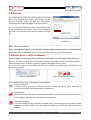
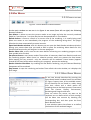
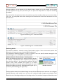
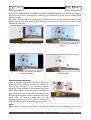
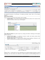
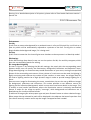
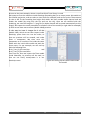
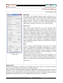
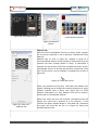
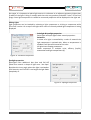
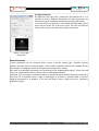
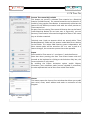
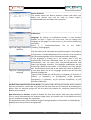
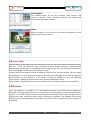
1
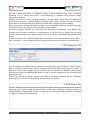
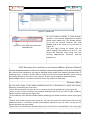
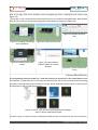
THEA FOR SKETCHUP
USER MANUAL
Revision 240.01
Copyright © Solid Iris Technologies
1.1 INTRODUCTION
Thea for SketchUp is an integrated version of Thea Render. This allows a creation of stunning
images right inside SketchUp and an interactive work with cameras, materials and lights. There is
an option of saving a complete Thea scene with all associated files for utilizing advanced tools
present in Thea Studio. Thea For SketchUp supports SketchUp Versions 6, 7, 8, 2013, 2014 and
2015 both Free(Make) and Pro, on both systems: Windows & OS X.
For downloads and plugin features please visit www.thearender.com/sketchup
1.2 INSTALLATION
MS WINDOWS
Please use the provided installer. It is advised to install Thea Render first. Please make sure you
have administrator rights while installing the plugin. To ensure that right-click the installer file and
select “Run as Administrator”.
A destination folder will be automatically found in case of SketchUp versions 6, 7, 8, 2013, 2014
and 2015.
MAC - OSX
Please use provided installer. The installer will guide you through the needed installation steps. It
also gives you the possibility to select the SketchUp version(s) for the plugin to be installed. It is
advised to install Thea Render first.
Materials installation is automatic too. For adding additional libraries though, a default folder for
putting these materials is:
SU8>> Macintosh HD/Library/Application Support/Google Sketchup 8/Sketchup/Materials
SU2013+>> Macintosh HD/Application/SketchUp2013/SketchUp/(right click) -> show content
/Contents/Resources/Content/Materials
Note: if you are using Lion, Snow Lion or higher version of OSX the ~Library forlder is hidden.
Please follow this link to learn how to access the folder:
http://mac.tutsplus.com/tutorials/productivity/how-to-reveal-your-library-folder-in-lion-ormountain-lion/
2
Copyright © Solid Iris Technologies
1.3 ACTIVATION
For activating the plugin you need to open the License
Input Form window from within Thea Studio or from
Thea for SketchUp plugin and add your Thea Studio
serial along with SketchUp plugin serial (see Figure 1).
Tip: you can open the License Input Form window from
inside SketchUp by pressing at Thea Tools window, at
Tools tab, the License button (see more details on page
26).
Figure 1: License Input Form
Plugins Tab
DEMO VERSION LIMITATIONS
Please not that while plugin is not licensed, rendered image resolution will be limited (800x600)
and watermarks will be added. All other features and functionality are fully supported.
1.4 GENERAL LAYOUT OF THE PLUGIN WINDOWS
Once the plugin is installed correctly a new item in the Plugins menu will appear (see Figure 2).
You can also have access to Thea for SketchUp through tools palette. Select “Show Thea toolbar”
from the plugin menu. A toolbar as seen in Figure 3 will appear on the screen.
Tip: in case the plugin is not enabled you can go at Preferences of SketchUp > Extensions and
enabled it at the list.
Figure 3: Thea Render Toolbar
Figure 2: Plugins Menu
User interface of the plugin is divided into two windows:
• Thea Tool Window
It allows setting up cameras, editing materials, placing and editing lights, exporting a
scene to Thea Studio and defining other preferences.
•
Thea Browser
This button opens Thea Browser Window that helps inserting easily inside SketchUp View
Thea models, materials, skies and SketchUp components
•
Thea Main Window
The main window displays currently rendered image, allows engines and rendering mode
selections, provides controls over the displayed rendering, its channels and environment
settings.
3
Copyright © Solid Iris Technologies
1.5 MAIN WINDOW
1.5.1 CONTROL BUTTONS
Figure 4: Control Buttons of Main Window
At the main window as we see it in Figure 4 we meet (from left to right) the following
buttons/indicators:
Save button: it allows to save the current render as an image and also the currently rendered
model as *.pack.thea or *.scn.thea file that can be opened then in Thea Studio.
Refresh button: it forces a refresh of a current view of the rendering. It is usually being used
when one wants to see immediately the progress of the rendering being done. The plugin
refreshes the view automatically at some intervals.
Open Batch Render window: with this button you can open the Batch Render window and select
among your scenes those that you need to add in queue for rendering. More details for this
window and functionality will be given in the next paragraph.
Render Phase info: at this area we see some details concerning our rendering progress or the
time needed to be finished.
Start/Pause button: start button makes Thea collect all necessary data from SketchUp and start
the rendering process. When there is a selection present, when one presses the start button
while keeping ALT key pressed - only the selection will be rendered. Pause button (appears
instead of the Start button when rendering is in progress) pauses the rendering.
Render Selection Check Box: by enabling this box before rendering, only the selected SketchUp
component will be rendered.
Stop button: it stops the rendering and makes Thea refresh the main window, so it displays the
final image.
1.5.1.1 BATCH RENDER WINDOW
As we have already described by pressing the
Open Batch Render window button the window
of Figure 5 opens. Here, all the available scenes
of our SketchUp file are listed in a table, along
with their names and a check option for
including them to the Batch process. Some extra
fields like Camera, Display, Environment,
Rendering and Progress also exist.
Once we select the scenes we want to be
rendered, we can define which of their settings
will be taken into account by checking the
corresponding box, and then press the Start
Batch Render button.
A new window opens that allows us to define
the location of the rendered images.
Figure 5: Thea Batch Render window
4
Copyright © Solid Iris Technologies
During rendering, at the bottom of the Batch Render window a list with details on the batch
process appears. At any point you want you can press the Stop button to stop the rendering
procedure.
Tip: the Refresh Scenes button clears the selections you have made to allow you to re enter them.
Tip2: you can save/load each scene settings at the Camera tab of the Tools window as we will
describe later.
1.5.2 MAIN WINDOW TABS
1.5.2.1 RENDERING TAB
Figure 6: Rendering Tab - Interactive Mode
Figure 7: Rendering Tab – Unbiased Mode
Rendering Modes
The control provides a selection among Thea Render engines. There are several options that
allow also an interactive type of rendering (IR indication).
For Interactive rendering engines, as seen in Figure 6, user can specify several settings for the
selected engine, as it is analytically described later.
Window Selection for Rendering – Overlay option
Below the Rendering Engines list, when Interactive Render
is enabled, a selection box with 4 options (see Figure 8)
lets the user define if the interactive rendering will be
shown inside Thea window (see Figure 9) or inside
SketchUp window as Overlay option (see Figure 10), inside
SketchUp window as Overlay with Edges (see Figure 11) or
as Overlay with Blending (see Figure 12).
Figure 8: Interactive Render Target
Window selection
Overlay option shows the rendered image on top of the SketchUp scene and user can navigate,
modify geometry, add models etc. and see the rendered image changing accordingly inside
SketchUp view. Blending mode gives a blending result of the rendered image and SketchUp scene
5
Copyright © Solid Iris Technologies
style. Initially a default style is used that gives better blending results but user is able to change to
the desired style while rendering. The rendering can be saved as an image, both in standard and
blending modes.
Tip: while using the Overlay, especially with blending, the best results can be achieved by using
Presto engines with GPU enabled for rendering and leaving CPU (at least a thread or two)
available for SketchUp.
Figure 9: Rendering inside Thea Window
Figure 10: Render in SketchUp Window as
Overlay
Figure 11: Render in SketchUp Window as
Overlay with edges
Figure 12: Render in SkertchUp as Overlay
with Blending
Interactive Region Rendering
Another available feature with the use of interactive
rendering inside SketchUp window (as Overlay or
Overlay with Blending) is the Interactive Region
Rendering, which provides a fast feedback from your
model and materials setup. You can mark the desired
part of SketchUp view (as Interactive Rendering is on)
by pressing Shift button and the same time with Thea
cursor draw the desired window. You can add
multiple regions too as seen in Figure 13. You can also
save the selected region by pressing the save button.
Figure 13: Interactive Region Rendering
Server
Server option is available for all modes and helps user perform a network rendering, with the use
6
Copyright © Solid Iris Technologies
of client machines.
Super-sampling
This corresponds to the super-sampling used for the image output, i.e. internal resolution
multiplier for anti-aliasing enhancement. None corresponds to no super-sampling, Normal to 2x2
and High to 3x3. Auto corresponds to no super-sampling for biased engine and 2x2 for unbiased
engines. Setting super-sampling to a higher level will generally improve anti-aliasing of the output
but will increase memory demands for storing the image (4 times in Normal level and 9 times in
High level). The time needed to render the scene will also be increased for biased engine. But for
the unbiased engines, the extra time needed to render the higher resolution image is usually
amortized by the reduced noise visible in the visualized (down-sampled) image. It is usually
suggested, for unbiased rendering, to change super-sampling to None for high resolution output
and High when there is persisting noise.
Bucket Render
With Bucket Render enabled (for Presto engines), once final rendering will start the technique of
Bucket rendering will be applied: rendering will start in tiles something that enables the rendering
of big resolutions and multiple channels and avoids any memory limitation issues.
Additional Settings
Threads
This is the entry for the render worker threads that will be used during rendering (not all
application process threads). The special value 0, same like Max, corresponds to the number of
logical cores on your machine. Exceeding this value (shown explicitly as the last value in the dropdown list) will have no benefit and actually an impact on performance.
Limits
• Time(min)
This is a parameter used to terminate the unbiased render process (it is only used by
unbiased render engines). It is given in minutes, and 0 is a special value corresponding to
no time limit at all.
• Samples/px
This allows to terminate an unbiased rendering when each pixel in a rendered image will
be sampled given number of times. In simple cases when no much caustics is present in a
model a value of 300 is sufficient. In more complex scenes higher values may be needed.
Interactive Modes
Those modes allow not only render the model as a static image, but also let interactively move a
camera around a model or adjust Sun position and see the rendering view being updated.
IR-Adaptive (AMC), IR-Presto (AO) and IR-Presto (MC) are the names of the available methods.
For fast rendering Presto engines can be selected as they use both your GPU+CPU (see Figure 14).
You can define extra parameters for devices used by Presto engines at Devices window.
Adaptive (AMC) method works also very well with multiple lights and complex lighting conditions.
Most important parameter for those engines is the 'Tracing Depth' which defines how many times
light bounces in a model. Values starting from 4 give good results in simple conditions, while a
higher number is needed when there are many highly reflective surfaces in a model.
7
Copyright © Solid Iris Technologies
Figure 14: GPU+CPU mode selection
For detailed description of parameters of rendering methods, please refer to Thea Render
manual.
Non-Interactive Modes
There are three non-Interactive high quality modes available:
• Adaptive (BSD): in many cases the fastest method based on presets, but it requires some
experience when a certain set-up is advantageous.
Figure 15: Adaptive (BSD) Presets
Two Unbiased methods: they don't require any settings and deliver renderings of the highest
quality. These are:
• Unbiased (TR1) engine: it is preferred in exterior renders and interiors where direct
lighting is the most dominant in the scene.
• Unbiased (TR2) mode: it is preferred when difficult indirect lighting is dominant in the
render or heavy caustics are present (such as a sun pool caustics).
1.5.2.2 DISPLAY TAB
Figure 16: Display Tab
Display Tab is a space where you can manipulate your rendered image and apply any postprocessing. First two sections are related to a render exposure and the following three to a
8
Copyright © Solid Iris Technologies
filtering. For a detailed description of all options, please refer to Thea Render Darkroom tutorial –
Section 2A.
1.5.2.3 ENVIRONMENT TAB
Figure 17: Environment Tab -IBL
Environment
Use Sky
It tells Thea to create a background for a rendered scene in a form of Physical Sky. It will look as a
clear sky which will be automatically adjusted to a position of the Sun. Turning this on makes
plugin disable the background image, if it is being used.
Use Sun
It tells Thea to create the Sun that will give same shadows as those present in a SketchUp model.
Edit Settings
At the Edit Settings drop down list we can see the options for IBL, Sun and Sky to appear, which
open the corresponding panels for editing.
IBL: Image Based Lighting
As seen in Figure 17 by selecting the IBL edit settings, the panel with the corresponding panel
appears where user can specify the Illumination, Background, Reflection and Refraction maps.
Image-based lighting is a convenient way to add illumination to your scene, coming from captured
photos of the surrounding environment. Since a photo of a real scene can be used, the lighting is
highly convincing and enhances the realism of your renders. In most cases, the images used for
this kind of lighting need to be of high dynamic range in order to provide enough lighting for a
scene.
One can use an image for illuminating the scene, nevertheless, he can also set up different images
for background, reflections and refractions. This makes possible to use different source for
lighting and for reflections/background, which in most cases need more details in the image. This
is actually a usual render optimization, where the illumination source is relatively low-detailed
texture in order for the image to quickly “converge”, while background and reflections use a
detailed map for visually enhanced results.
To add one of image types select proper type and press 'Browse' button to select a desired image.
When proper bitmap selected its path will be displayed in the adjacent horizontal input box. One
can control intensity, rotation and a way the image is wrapped around a model.
9
Copyright © Solid Iris Technologies
Sun
Figure 18: Sun Settings
Manual Sun option helps to position the sun in an arbitrary
position regardless of model's geographic location. You are able
to
adjust
the
sun
Polar
Angle
and
Azimuth, either by entering the desired values, or manually, by
opening the Environment Preview (Figure 19) and clicking
preferred location in the preview.
Environment Preview can be opened by clicking a blue icon in
Environment Settings. This window shows a preview of
environment which is being automatically updated. When
Manual Sun is disabled and IBL lighting used, then the
environment map can be rotated by dragging the preview
image.
Figure 19: Environment
Preview
Sky
Figure 20: Sky Settings
By selecting the Sky at the Edit Settings list, the sky settings appear as seen in Figure 20.
1.5.2.4 CHANNELS TAB
Figure 21: Channels Tab
10
Copyright © Solid Iris Technologies
This tab is being used when an additional image is being required, other than a standard
rendering. This is mostly used when a post-processing is intended using external image
manipulation program.
Available channels are: Color (standard rendering) , Normal, Depth, Alpha, Object Id, Material Id
and channels specific to Adaptive(BSD) rendering mode: Direct, Ambient Occlusion, Global
Illumination, Sub-Surface Scattering, Reflection, Refraction, Transparency and Irradiance.
Some channels like Shadow Channel, Raw Diffuse Color, Raw Diffuse Lighting, Raw Diffuse GI, Self
Luminance and Pass per Light are only available to Presto engines.
Luminance Analysis describe the luminance and illuminance distribution. Thea Render can
compute both of them. Luminance is computed out of the box for any image that you have
already rendered and for any render settings. Illuminance can be computed by the Adaptive BSD
engine.
To view the analysis of a rendered image select 'Photometric' from the drop down menu. 'Min Il –
Lum' and 'Max Il – Lum' parameters control a range of illumination the analysis is performed on.
1.5.2.5 ANIMATION TAB
Figure 22: Animation Tab
This tab contains all needed settings related to animation. Here you can select if camera and/or
objects animations will be used. Camera movement will follow exactly same path as it moves in
SketchUp. Field of view changes during animation won't be applied. For Adaptive (BSD) engine
you can also enable the Walkthrough option (in case of camera movement only) and define the
lighting percision.
'Frames per second' parameter controls how fluid an exported animation will be. Animation
rendering can be only started by pressing 'Render Animation' button.
1.5.2.6 CONSOLE TAB
Thea For SketchUp uses the console to send you messages informing you about current state of
rendering, time in which rendering was finished and warnings. In general visiting the console is
recommended if something doesn't work as expected. It can help you finding a source of problem
- no light in a model or missing texture.
11
Copyright © Solid Iris Technologies
1.6 THEA BROWSER WINDOW
1.6.1 GENERAL
Within Thea Browser window you can find the
available Thea Models and Materials libraries
and Skies.
By seeing their previews you can select the
one you want, double click on it and then by
going inside SketchUp scene you can either
paint a surface with this material or add the
model to the desired point. Sky is added
directly (and enabled) at the IBL of the
Environment tab. Thea Browser displays also
SketchUp components and lets you insert
them.
Figure 23: Thea Browser
Figure 25: Preview and inserting a model
Figure 24: Preview and using a material
Tip: by right clicking on the Custom Folder
option you can either refresh your contents or
choose your own folder with materials or
models. You can also remove a selected folder
by right clicking on it.
Figure 26: Right Click Options
12
Copyright © Solid Iris Technologies
Figure 27: Model Info
An extra feature available at Thea Browser
window is the External Dependencies option
found under Model Info. This window allows
us to see the external Textures, IBLs and
Models used in the scene, as we see then in
Figure 27.
Tip: with right clicking on Model Info an
option appears that allows us to save in *.zip
format the SketchUp scene along with the
existing dependencies (textures, external
models etc.).
Figure 28: Save SketchUp model with
dependencies
1.6.1 ADDITIONAL INFO FOR CREATING AND INSERTING MODELS (EXTERNAL PROXIES)
Thea For SketchUp allows an insertion of complex, external Thea models in a form of a bounding
box, which will be replaced by the original, detailed model inside Thea rendering window when a
rendering starts. To insert a model select it firstly from the Thea Content Browser, either among
the existing libraries or from your own collection or from those created as described below.
Simply double click on it to select it and then insert the model into SketchUp.
CREATING A PROXY
You can easily create a Thea model (mod.thea) and use it afterwords as a proxy from within
SketchUp, by following the next steps:
- Select the component you want to use as a proxy and name it appropriately (see Figure 29).
- Select a small camera resolution (for example 150x150) and find a nice view of your model to
make a preview rendering (see Figure 30).
- At Thea Render main window enable (before rendering) the Render Selection option (see Figure
31).
- Render your model preview (see Figure 32). You can now press the Save button and save the
rendered model in a mod.thea format (Thea Model). Otherwise you can save it by the use of
Content Browser (see next steps).
- Open then the Thea Browser window. Select at the left side list a desired folder. Then with right
13
Copyright © Solid Iris Technologies
click at the right side of the window, press the appearing “Save *.mod.thea here” option (see
Figure 33).
- The proxy is now created and can be found from now on inside the selected folder. With double
click you can insert the model (bounding box) inside SketchUp scene (see Figure 34).
Figure 31: Render Selection
Only
Figure 29: Creating and Saving
the component
Figure 30: Setup Camera View
Figure 32: Make the preview
render
Figure 33: Save model to
selected folder of Content
Browser
Figure 34: Use the model as a
Proxy
CREATING PROXY PREVIEW
A corresponding SketchUp model (in *.mod.skp format) can be written in the same folder as the
Thea Model (*.mod.thea) and in this way this SketchUp file will be used instead of the bounding
box when inserting the external models as a proxy. When mod.skp is present then its preview will
be displayed on top of mod.thea preview.
Figure 35: Birch_Tree_02 has a mod.skp preview available,
seen on top of mod.thea preview
The basic steps to create correctly a Sketchup model that will correspond to the Thea model can
14
Copyright © Solid Iris Technologies
be seen at the next example, where a tree from Birch Trees library is used.
We import at first the mod.thea inside Sketchup (bounding box) in an empty scene. We switch to
the Parallel projection, and we select a view (front for example) and we set up the Thea camera
so that it will fit the bounding box height and width. We then enable alpha channel and we
render the model (by using only the sun and not the sky). Once we are satisfied with the
rendering, we save the image as a *.png file (its alpha channel will be saved automatically at this
image). We repeat the same procedure for another side of the model (its right side for example)
so that we can have more correct (double sided) preview.
In this way he have 2 images for 2 of the
models sides, which we can then import inside
SketchUp, place them one into the other, so
that our preview will be created, and make
them a component. We then save this
component as a *mod.skp file inside the same
folder with the initial thea model and with the
same name. For our example, we will end up
with the following files:
Birch_Tree_03_6m.mod.skp
and
Birch_Tree_03_6m.mod.thea
From now on, once we import the Thea model
inside SketchUp, its preview will be used, so
that we can easily move/rotate it in our
SketchUp scene.
15
Figure 36: setting up the camera and render
the model
Copyright © Solid Iris Technologies
1.7 THEA TOOL WINDOW
1.7.1 CAMERA TAB
Resolution
The 'Width' and 'Height' settings control resolution of a
rendered image. Please note that interactive rendering modes
use full area of plugin's main window and render exactly at
same resolution. The Plus & Minus buttons increase or
decrease current resolution two fold. (H)orizontal\(V)ertical
toggle button changes orientation of the rendered image.
Aspect ratio
This setting control proportions of a final rendered image.
When "SU Window" option is selected the resolution of a
rendered image will be adjusted to be same aspect ratio as
model view in SketchUp. When "Thea Window" is selected the
resolution is adjusted to reflect current proportions of main
render view. A typical proportions of 4:3 is characteristic for old
type of monitors with resolutions of 800x600, 1024x768,
1600x1200. Wide screen proportions of 16:9 is more common
in new monitors with resolution of 1600x900, 1920x1080.
When creating a panoramic spherical or hemispherical image a
correct ratio is 2:1.
LENS
Figure 37: Thea Tool Camera Tab
Thea can project a rendered image on the screen in a standard
manner – perspective or orthogonal, depending on a current
view in SketchUp or using Spherical or Cylindrical projection.
The spherical projection allows creating renderings of virtual
panoramas that can be viewed in external programs. Correct
aspect ratio of such an image is 2:1.
Shutter speed controls a motion blur which appears in an
animated scene. Thea gives you control over a diaphragm of a
camera. It can be circular or polygonal defined by a number of
blades. This influences a look of a 'depth of field' effect and a
motion blur.
Depth of Field
The depth of field can be controlled in the plugin in two ways. Either by 'f-number' of camera
lenses or by percentage of a "blurriness" of a rendered image.
When Auto Focus is enabled plugin automatically adjusts focus distance to keep what is visible in
a camera 'in focus' when possible. Focus distance displays a manual distance at which a camera is
focused at. To set that value click 'Set' button and select a point in a model. The distance will be
calculated automatically. The value is disregarded when 'Auto Focus' is enabled.
16
Copyright © Solid Iris Technologies
Z-Clipping
With these two options you can enable a Near and Far vertical clipping by defining the distance in
meters. In this way you are able to create vertical cuts and see inside interior rooms for example
without the need to cut a wall.
Level Camera
This button levels camera without changing its' position. It is helpful especially when setting-up a
camera for a panoramic shot.
Scene Settings
This section allows associating Thea Render settings with SketchUp scenes/pages. It works same
way as it is done in SketchUp with scene settings except they are not loaded automatically when a
scene is selected, but it has to be done manually by clicking "Load' button. To save settings select
a scene name from the list, mark setting types you want to store and press 'Save' button
Available options are: Camera Settings, Display Settings, Sky/IBL Settings, Render Settings.
1.7.2 MATERIAL TAB
Introduction
Before explaining in detail the Material Tab of the Thea Tools Window, we need to give a quick
description of the available ways of adding a Thea material inside SketchUp.
As we will describe below, you can now choose between three available ways:
1. Double click on a painted face with the Thea tool cursor, open Thea Material Lab (see Figure
38), create your material or choose one from the available libraries (or your own folders) and
apply it to your SketchUp face. You can choose to Accept the changes or Reject them (and return
back to the material without any changes applied to it).
2. Click once on a painted face, with the Thea cursor tool, and see its details at the Material tab
(see next paragraph and Figure 39) and then choose one of the existing presets for the material
and edit it according to your needs.
3. Find Thea materials (converted in *.skm format) inside SketchUp Paint Bucket (see Figure 40)
and apply them directly to your SketchUp surfaces. Conversion tool is also available for making
your thea materials being converted into SketchUp materials and see them at the Paint Bucket
(more details can be found at the Tools tab).
17
Copyright © Solid Iris Technologies
Figure 40: Thea Materials
inside SketchUp Bucket
Figure 38: Thea Material Lab
Figure 39: Material
Presets
Material Tab
With the use of the Material Tab we can either select a preset
for one of our materials or see its preview, if edited with Thea
Mat Lab.
Material tab, as seen in Figure 41, displays a name of a
currently edited material and a preview of Thea material (if the
material has been already edited in Thea). To select/edit a
material one has to open Thea Tool and while the tool is active,
click/double click on an already painted face in SketchUp. Thea
Tool is active when a cursor changes it's appearance as seen in
Figure 42.
Figure 42: Thea Tool Cursor
When you double-click the face, Thea Mat Lab window will
appear, allowing you to modify the material properties or apply
another material from a library (see Figure 38). For more
detailed information on Thea Material Lab and its options,
please refer to Thea Render Manual.
Figure 41: Thea Tool –
Material Tab
When user clicks just once the material, the Material tab will
display the name and a preview of a the material - if the
material has been already edited in Thea Mat Lab- otherwise
the panel will show like we see it in Figure 41, where the
available presets exist.
18
Copyright © Solid Iris Technologies
Tip: In interactive mode cursor changes to a cross-hair and allows selection of a material directly
in a rendered image. Single click shows material properties and settings while double click
maximizes render window.
General Notes
The custom color by default is linked with SketchUp material color. By pressing the SU button, you
are able to use a custom color instead the one already selected in SketchUp and change your
material accordingly. By pressing the SU button once again you can decide to choose SketchUp
material again or an external texture.
Figure 43: SU Button
The external texture once specified can be imported into SketchUp by right-click > Import texture.
The imported texture size will be automatically reduced.
When texture type is 'EXT'ernal with a right-click one can import a downsized texture into
SketchUp.
Additionally as seen in Figure 68 for the Emitter, SU button has the option of specifying a
temperature(K) for the emitter.
All material types except Emitter have option of using bump map. The map can employ same
texture as SketchUp material has or an external texture.
All material types except Mirror can use as a base: SketchUp material, an independently defined
color or an external texture.
You can remove also a Thea material, by doing a right click on the preview area and press
“Remove Material” button.
Below we can see a table with all the materials presets that exist at Material Tab, along with their
available options, description and an example preview.
19
Copyright © Solid Iris Technologies
Material Preset
Default
Description
Available Options
Example Preview
This default type is a pure diffuse
material.
Figure 44: Default
Material options
Figure 45: Default
Material preview
Matte
Plastic
Thin
Translucent
This material type represents a very
rough surface. It provides control
over
Reflections
and
Sigma
Roughness, which influences how
well an object accepts light from all
directions. It makes the material to
appear more flat.
This type of material behaves as
plastic. It provides Roughness and
Reflections parameters. It is a good
base for a whole range of plastics
from very rough and dull to polished
and shiny.
This type produces a single sided
translucent material which is perfect
for curtains and other nonvolumetric objects. One can control
its transparency percentage.
20
Figure 46: Matte
Material options
Figure 48: Plastic
Material options
Figure 50: Thin
Translucent Material
options
Figure 47: Matte
Material preview
Figure 49: Plastic
Material preview
Figure 51: Thin
Translucent
Material preview
Copyright © Solid Iris Technologies
Lacquer
Ceramic
This type represents a lacquered
surface typically seen as a finish of
timber floors. It provides Reflections
and Roughness parameters. With
the roughness set to 0 it resembles
polished material and with higher Figure 52: Lacquer
Material options
values a satin appearance.
Figure 53: Lacquer
Material preview
This type describes a ceramic
material with a glossy finish.
Figure 54: Ceramic
Material options
Figure 55: Ceramic
Material preview
Car Paint
The material using this preset will
resemble a car paint. When
'Metallic' option is enabled, the
paint will behave as it would contain
uniformly spread metallic flakes.
Figure 56: Car Paint
Material options
Figure 57: Car Paint
Material preview
Colored Metal
This type is designed to give a metal
appearance
with
pronounced
reflections.
Figure 58: Colored
Metal Material
options
Figure 59: Colored
Metal Material
preview
21
Copyright © Solid Iris Technologies
Mirror
The material will behave as a mirror
surface. This type overrides
SketchUp material color.
Figure 60: Mirror
Material options
Figure 61: Mirror
Material preview
Thin Glass
Thick Glass
Emitter
This type describes an architectural
glass with a control over Metallic
reflection it may posses due to
applied coatings. This material
doesn't require a volume of a
geometry and is especially suited for
non solid, thin face objects.
This type produces a volumetric
glass which takes into account the
refractions within object volume.
Roughness of a surface and intensity
of Reflections can be controlled.
This type turns a painted face into a
light emitter. Its power is specified
in several units. Temperature can
also be specified instead of default
color/texture. There is an option to
make emitter not visible in a
rendering or to make it “passive” - it
will have a luminous appearance,
but will not cast the light into a
scene.
22
Figure 62: Thin
Glass Material
options
Figure 64: Thick
Glass Material
options
Figure 66: Emitter
Material options
Figure 63: Thin
Glass Material
preview
Figure 65: Thick
Glass Material
preview
Figure 67: Emitter
Material preview
Copyright © Solid Iris Technologies
Figure 68: Enabling Emitter Temperature
Thea Material
(Mat-Lab)
This type uses full Thea Material
editor from the Studio and allows
full control over material properties
(such as Clipping that we see in the Figure 69: Mat-Lab
example preview). Any of previous Material options
material types can be also edited
this way.
“Remove Thea Material' button
removes all Thea material settings
associated with SketchUp material.
Figure 70: Mat-Lab
Material preview
1.7.3 LIGHT TAB
SketchUp doesn't have its' native light sources. Thea for SketchUp uses components with a special
names to define position and orientation of lights. There are thee light types available in the plugin:
• Point Light: a regular omnidirectional spherical light.
• Spot Light: a directional light that allows focusing of a light cone on a chosen area in a
model.
• IES Light: a light based on scientifically measured real life values, provided by light-bulbs
and fixture manufacturers in a form of *.ies files.
One can also paint a face with a material using emittance and in this way create an area light.
Front side of the face will be emitting light.
Creating Lights
Light tab allows a creation and editing properties of
light components. To create a light open Thea Tool
Widnow and select 'Light' tab. At the bottom there
are three buttons responsible for creation of three
types of lights. On the start of light placing tool user
Figure 71: Create Lights Options
is asked to show in SketchUp model a location of a
source of light by right clicking and subsequently a 'target' of the light. In case of a point-light only
the distance from the source to target is being used to calculate a sufficient light power to reach
23
Copyright © Solid Iris Technologies
the target. It is important to place light sources in a distance to an adjacent geometry higher than
a radius of the light. Failing to comply with that rule may produce undesired "noise" in the final
image. Once light component is created its name and properties will be displayed in the Light tab.
Editing Lights
Light properties can be invoked by selecting a light component or clicking a component while
Thea Tool is active. On a top of the Light tab a name of currently edited light component is being
displayed.
Pointlight & Spotlight properties
Point-lights and spot-lights share several properties:
Emittance
A colour of a light is controlled by a color of material the
light component is painted with. When a temperature is
enabled it will be used instead of the color.
All lights have flowing parameters:
Power expressed in multiple units, efficacy (lm/W),
attenuation and light temperature (K).
Figure 72: Emittance Properties
Spotlight properties
Spot-lights have additional Hot Spot and Fall Off
values that control a shape of light cone. 'Hot Spot'
describes the inner angle where the light is emitted at
a full intensity and 'Fall Off' is and angle the light fades
completely at.
Figure 73: Spotlight Properties
24
Copyright © Solid Iris Technologies
IES Light properties
By default an IES light have a sample.ies file loaded into it. It is
possible to load a different description of light distribution by
selecting it from a dropdown menu and pressing 'Load' button.
To use an IES file not present in Thea Studio IES files folder, select
from the list 'Other file' and press 'Load'. You will be asked to
select a file you want to save into the light component.
Figure 74: IES Light
Properties
General Properties
A light component can be 'Enabled' which means it will be casting light. 'Shadow' controls
whether the light will be casting shadows. 'Soft Shadow' specifies whether the shadow will be
soft, based on a imaginary radius of the light source expressed in meters.
'Min Rays' and 'Max Rays' parameters are used only by the Adaptive(BSD) engine. Those are used
rarely. For a detailed description, please refer to Thea Render Manual.
'Container' lets you assign a container-material in which the light is placed. Setting this material is
valid only for a situations when a light is submerged in a water or placed inside a material
congaing properties of a medium. It can be also used to force a light to show a volumetric
projection of light.
25
Copyright © Solid Iris Technologies
1.7.4 TOOLS TAB
Convert Thea material(s) to SKM
This button can convert a selected Thea material to a SketchUp
material (in SKM format). The created materials can be placed in a
model by using regular Paint Bucket. It automatically optimizes the
texture of the SketchUp material and adds the same preview as
Thea material has.
So apart from the existing Thea material libraries that can be found
inside SketchUp Bucket (as we have seen in Figure 40), you can
have any Thea material converted and applied to faces in the same
way as all other materials.
Technical note: Paths to textures which are stored within 'Thea
Render/Materials' folder will be written inside SKM file as relative
to that folder. This makes SKM libraries system independent. All
other texture paths will be stored as full. In a case a path to a
texture changes, the conversion process has to be repeated.
Export
Saves model as Thea scene in *.scn.thea or *.pack.thea format.
Note that when pressing the Save Thea Scene button with ALT
pressed at the keyboard or clicking at the Selection Only box, the
current selection is only saved.
By enabling the Export Animation option and/or Objects
movement, your animation paths (scenes included in animation)
are also exported and can be then seen inside Thea Studio.
Figure 75: Thea Tools Tab
License
This button opens the License Form window that allows you to add
your serial, name, email address and make an activation of the
program.
Figure 76: License Input
Form
26
Copyright © Solid Iris Technologies
Device Selection
This button opens the Device Selection button that helps you
define the devices that will be used by Presto engine,
enable/disable them and adjust their priorities.
Figure 77: Device Selection
Preferences
Language: By clicking on Preferences button, a new window
appears as seen in Figure 78. From here, you can change the
Language of the plugin. In order to do so, you need to follow the
next steps:
There is a TheaForSketchUp.po file in the folder:
Figure 78: Plugin Preferences Thea4SU_file/languages/
Window
This file needs to be translated using Poedit program. The program
will generate a TheaForSketchUp.mo file, that has to be copied to
the corresponding folder of the selected translation language.
If the language is already set in the system then it will be
automatically used when SketchUp starts. If it has not been set
automatically, user can open Thea Tool/Tools/Preferences and
select the language manually. The language modification will be
active after SketchUp will restart. If for example you have placed
the TheaForSketchUp.mo file at the folder with name es (Spanish)
Figure 79: Selecting another at the drop down list of the Language window you will see the
Language
Spanish language too.
Typical Country Codes are: de (German), es (Spanish), fr (French), it
(Italian), ja (Japanese), pt (Portuguese), pt_BR (Brazilian
Portuguese), ru (Russian), zh_CN (Chinese Simplified), zh_TW
(Chinese Traditional).
Use Back face material when Front absent: This option helps dealing with models where multiple
faces are painted on a back-side only (whereas the front face has no material). By enabling this
option Thea for SketchUp plugin will use the back face material for rendering instead of the
default white material.
Auto Save every x minutes: enable or disable the Auto Save option. With Auto Save enabled,
Thea is saving automatically the rendered image every 10 minutes (this is the default time but
you are allowed to change this parameter).
The AutoSave location of the rendered images is being displayed in the Console in the Rendering
Window when the window is being opened.
27
Copyright © Solid Iris Technologies
Check Updates
This window helps you see the available Thea versions and
resources libraries, check out their previews and details and
download/install those needed.
Figure 80: Check for Updates
About
With this option you are able to see some information on the
plugin and its current version.
Figure 81: About window
1.8 LICENSE TERMS
Solid Iris grants to You a personal, non-transferable, and non-exclusive license to download, install
and use “Thea for SketchUp” and associated printed and/or electronic documentation
accompanying the Software, in accordance with this agreement. This license does not under any
circumstances grant ownership of the Software to You.
A single copy of the program can be installed and used by You, on one machine. You can install
the application on up to two more machines, provided that the plugin is not used or executed
simultaneously on any machines. If You wish to install the Software or use the Software
concurrently on additional machines You must purchase additional licenses.
Demo version is provided for evaluation only and its use for commercial purposes is prohibited.
1.9 DISCLAIMER
“Thea for SketchUp” is provided "as-is" and without warranty of any kind, express, implied or
otherwise, including without limitation, any warranty of merchantability or fitness for a particular
purpose. In no event shall the author of this software be held liable for data loss, damages, loss of
profits or any other kind of loss while using or misusing this software. The software must not be
modified, you may not decompile, disassemble. Any kind of reverse engineering of the software is
prohibited.
28
Copyright © Solid Iris Technologies