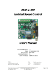
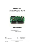
1
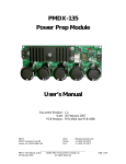
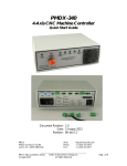
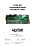
PMDX-104
4-Channel Relay Output Board
User’s Manual
Document Revision: 1.0
Date: 23 February 2010
PMDX
9704-D Gunston Cove Rd
Lorton, VA 22079-2366 USA
PMDX-104_Manual_10.doc
23 February 2010
Web:
Phone:
FAX:
http://www.pmdx.com
+1 (703) 372-2975
+1 (703) 372-2977
©2010, Practical Micro Design, Inc.
All Rights Reserved
Page 1 of 8
PMDX-104 4-Channel Relay Output Board User’s Manual
Document Revision: 1.0
Table of Contents
1.0
Overview.................................................................................................................................... 3
1.1
Important Safety Information ........................................................................................................................... 3
1.2
Warranty Summary............................................................................................................................................. 3
1.3
Features.................................................................................................................................................................. 4
1.4
Updates to this Manual ...................................................................................................................................... 4
2.0
Installation and Operation ...................................................................................................... 4
2.1
Connecting to a PMDX-125 ............................................................................................................................. 5
2.2
Connecting to a PMDX-122 ............................................................................................................................. 5
2.3
Connecting to a PMDX-132 ............................................................................................................................. 6
3.0
Mechanical Specifications........................................................................................................ 7
4.0
Electrical and Environmental Specifications ........................................................................ 7
Appendix A – Warranty...................................................................................................................... 8
PMDX-104_Manual_10.doc
23 February 2010
©2010, Practical Micro Design, Inc.
All Rights Reserved
Page 2 of 8
PMDX-104 4-Channel Relay Output Board User’s Manual
Document Revision: 1.0
1.0
Overview
This document describes the configuration and operation of the PMDX-104 4-Channel Relay Output
Board. The PMDX-104 4-Channel Relay Output Board is useful for providing low-speed isolated control
signals, or for controlled moderate loads as an add-on to a standard break-out board.
1.1
Important Safety Information
The PMDX-104 4-Channel Relay Output Board is intended for integration by the purchaser into industrial
control systems. It is solely the purchaser's responsibility to assure that the system is configured in a
manner consistent with applicable safety requirements. Practical Micro Design, Inc. does not control how
these parts are integrated into the purchaser's system and cannot be responsible for guaranteeing the
safety of your system.
The PMDX-104 4-Channel Relay Output Board is not guaranteed to be fail-safe. The system into which
the PMDX-104 4-Channel Relay Output Board is installed should provide fail-safe protection and
emergency stop capability.
Automated machine tools, into which the PMDX-104 4-Channel Relay Output Board may be integrated,
can cause injury. Precautions should be taken to assure that operators are trained in their proper
operation and safety procedures, and that they are protected from moving parts that may be under
remote control and may move unexpectedly.
This product may not be used in life support or other critical safety applications.
1.2
Warranty Summary
The PMDX-104 4-Channel Relay Output Board is warranted against failure due to defective parts or
workmanship for 90 days from the date of sale. Refer to Appendix A for complete warranty details.
NOTE: If you have an item requiring service, please see the
“Warranty and Repairs” page on the PMDX web site
(http://www.pmdx.com) for return instructions.
In general, the purchaser must pay shipping to send the unit to PMDX. For repairs covered under
warranty and with return shipping to a USA address PMDX will ship the repaired unit back to you via
ground transportation at our expense. Repairs are normally completed within 10 business days. See
Appendix A for our complete warranty details. Please see the “Warranty and Repairs” page on
our web site (http://www.pmdx.com) for full details of our repair and shipping policies.
PMDX-104_Manual_10.doc
23 February 2010
©2010, Practical Micro Design, Inc.
All Rights Reserved
Page 3 of 8
PMDX-104 4-Channel Relay Output Board User’s Manual
Document Revision: 1.0
1.3
Features
The PMDX-104 4-Channel Relay Output Board has the following features:
•
Electromechanical relay outputs support
AC or DC loads up to 5 amperes maximum
•
Outputs can provide isolated "switch
closures" to control VFD's (variable
frequency drives) or drive 24 volt DC
inputs for PLC’s (programmable logic
controllers)
•
Clamp style screw terminal strips for inputs
and outputs allow use with any breakout
board
•
Logic level control inputs (5 volt TTL or
CMOS)
•
Inputs have default pull-down resistors so
unconnected inputs turn the relays off
•
Outputs protected from spikes when
turning off inductive loads
•
•
LED indicators on each channel
Requires 5 volts power, can be powered
directly by PMDX-125
•
Can be used with other brands of break-out
boards
1.4
Updates to this Manual
Check the PMDX web site for revisions or updates to this manual (http://www.pmdx.com). The latest
revision of this manual is available on the PMDX-104 4-Channel Relay Output Board page (follow the links
from the main page).
2.0
Installation and Operation
Note that all PMDX breakout boards have sufficient +5V power available to power the PMDX-104 and
output signals of sufficient drive strength to drive the relay control inputs.
Connectors J1, J2, J3 and J4 provide the “normally open” (NO) contacts from each of the four relays.
The PMDX-104’s input signal connector is configured so that the signals line up with either of the
PMDX-125’s output connector (PMDX-125 connectors J5 and J6). This allows you to place the
PMDX-104 next to the PMDX-125 and run wires directly between the two connectors.
Pin Label
+5V
“A”
“B”
“C”
“D”
PCgnd
Description
+5VDC regulated power supply input
Relay “A” control input
Relay “B” control input
Relay “C” control input
Relay “D” control input
Ground (power supply return)
Table 1 –Input Signal Connector Pin-Out (J5)
NOTE:
The PMDX-104 does not implement a “charge pump” or E-Stop. If your application
requires that the relay outputs be disabled by a “charge pump” or E-Stop, then the
board driving the signals to the PMDX-104 must implement the “charge pump”
and/or E-Stop function. The board should then disabled the signals to the PMDX-104
(i.e. drive them low) when it detects a “charge pump” failure or E-Stop condition.
PMDX-104_Manual_10.doc
23 February 2010
©2010, Practical Micro Design, Inc.
All Rights Reserved
Page 4 of 8
PMDX-104 4-Channel Relay Output Board User’s Manual
Document Revision: 1.0
2.1
Connecting to a PMDX-125
PMDX-125
J6
PC+5V
"1"
"2"
"3"
"4"
Note:
Similar connections can
be made to the
PMDX-125 connector J6.
J1
PMDX-104
PCgnd
J5
"A"
+5V
J2
PC+5V
"A"
"A"
"B"
"B"
"C"
"C"
"B"
J3
"C"
"D"
"D"
PCgnd
J4
PCgnd
J5 Inputs
"D"
Figure 1 - PMDX-104 to PMDX-125 (J5) Connections
2.2
Connecting to a PMDX-122
PMDX-104
J11
J12
See text
about pin 17
PCgnd
PWR
Alt In
"D"
pin17
"C"
pin16
"B"
pin14
"A"
"C"
"B"
+5V
+5V AUX OUT
"A"
J8
PMDX-122
"D"
GND
J5 Inputs
N/C
RLY
COM
N/O
pin8 pin9 COM
J7
J4
Figure 2 - PMDX-104 to PMDX-122 Connections
NOTE:
In order to power the PMDX-104 from the PMDX-122, the PMDX-122 must be
powered from a 9 to 12V AC or DC power supply or a regulated +5V supply. You
cannot power the PMDX-104 from a PMDX-122 when the PMDX-122 is powered
from a USB port.
WARNING – If you have parallel port pin 17 configured as a “charge pump” signal, you
MUST configure the PMDX-122 to output “CP OK” (charge pump OK) on
its pin 17 output in order to connect this pin to the PMDX-104. Please
refer to the PMDX-122 User’s Manual for more information on configuring
the “pin 17” output.
Connecting the pin 17 output to the PMDX-104 when pin 17 is the “raw”
charge pump signal will cause erratic operation of the PMDX-104 relay.
PMDX-104_Manual_10.doc
23 February 2010
©2010, Practical Micro Design, Inc.
All Rights Reserved
Page 5 of 8
PMDX-104 4-Channel Relay Output Board User’s Manual
Document Revision: 1.0
2.3
Connecting to a PMDX-132
The following diagram shows the PMDX-104 connected to a PMDX-132. Note that the PMDX-132 has
two on-board relays that can be enabled or disabled via jumpers. When enabled these PMDX-132 relays
are controlled by parallel port pins 1 and 14. If the PMDX-104 is connected to the PMDX-132 for
parallel port pins 1 and 14 (as shown by the dotted lines), and the PMDX-132 relays are enabled, then the
relays on the PMDX-104 will operate in parallel with the relays on the PMDX-132. This can be useful if
you need to switch two separate circuits with a single parallel port pin.
WARNING – If you have parallel port pin 17 configured as a “charge pump” signal, you
MUST configure the PMDX-132 to output “CP OK” (charge pump OK) on
its pin 17 output in order to connect to the PMDX-104. Please refer to the
PMDX-132 User’s Manual for more information on configuring the “pin
17” output.
Connecting the pin 17 output to the PMDX-104 when pin 17 is the “raw”
charge pump signal will cause erratic operation of the PMDX-104 relay.
J10
fault*
GND
EStop
GND
MtrDis*
J1
PMDX-104
GND
J9
"A"
AUX +5V
+5V
J2
1
"A"
"B"
**
"B"
J3
"C"
16
"D"
17
PCgnd
J4
J5 Inputs
"D"
14
"C"
PMDX-132
GND
J8
AUX +5V
11
** See text
12
13
15
GND
Figure 3 - PMDX-104 to PMDX-132 Connections
PMDX-104_Manual_10.doc
23 February 2010
©2010, Practical Micro Design, Inc.
All Rights Reserved
Page 6 of 8
PMDX-104 4-Channel Relay Output Board User’s Manual
Document Revision: 1.0
3.0
Mechanical Specifications
4 each holes for #6
screw to mount board
2.500"
0.175"
2.325"
2.500"
2.325"
0.000"
0.175"
0.000"
Figure 4 - PMDX-104 4-Channel Relay Output Board Dimensions
WARNING:
4.0
The PMDX-104 4-Channel Relay Output Board should be
protected from liquids, dirt, or chips (especially metal chips which
can cause shorts) coming in contact with the board.
Electrical and Environmental Specifications
Power Supply:
+5V DC input, 100mA maximum
Relay Contacts:
5 Amperes maximum
250VAC or 30VDC maximum
Environmental:
Temperature:
Relative Humidity:
PMDX-104_Manual_10.doc
23 February 2010
0° to +55° C
20% to 80% relative humidity, non-condensing
©2010, Practical Micro Design, Inc.
All Rights Reserved
Page 7 of 8
PMDX-104 4-Channel Relay Output Board User’s Manual
Document Revision: 1.0
Appendix A – Warranty
Statement
Practical Micro Design, Inc. (PMD) warrants that this hardware product is in good working
condition, according to its specifications at the time of shipment, for a period of 90 days
from the date it was shipped from PMD. Should the product, in PMD's opinion, malfunction
within the warranty period, PMD will repair or replace the product without charge. Any
replaced parts become the property of PMD. This warranty does not apply to the software
component of a product or to a product which has been damaged due to accident, misuse,
abuse, improper installation, usage not in accordance with product specifications and
instructions, natural or personal disaster or unauthorized alterations, repairs or
modifications.
Limitations
All warranties for this product, expressed or implied, are limited to 90 days from the date of
purchase and no warranties, expressed or implied, will apply after that period.
All warranties for this product, expressed or implied, shall extend only to the original
purchaser.
The liability of Practical Micro Design, Inc. in respect of any defective product will be limited
to the repair or replacement of such product. Practical Micro Design, Inc. may use new or
equivalent to new replacement parts.
Practical Micro Design, Inc. makes no other representations or warranties as to fitness for
purpose, merchantability or otherwise in respect of the product. No other representations,
warranties or conditions, shall be implied by statute or otherwise.
In no event shall Practical Micro Design, Inc. be responsible or liable for any damages arising
(a) from the use of the product;
(b) from the loss of use of the product;
(c) from the loss of revenue or profit resulting from the use of the product; or
(d) as a result of any event, circumstance, action or abuse beyond the control of Practical
Micro Design, Inc.
whether such damages be direct, indirect, consequential, special or otherwise and whether
such damages are incurred by the person to whom this warranty extends or a third party.
PMDX-104_Manual_10.doc
23 February 2010
©2010, Practical Micro Design, Inc.
All Rights Reserved
Page 8 of 8