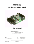
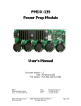
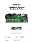
1
PMDX-340
4-Axis CNC Machine Controller
Quick Start Guide
Document Revision: 1.0
Date: 5 August 2013
Revision: B6 and C2
PMDX
9704-D Gunston Cove Rd
Lorton, VA 22079-2366 USA
PMDX-340_QuickStart_10.doc
5 August 2013
Web:
Phone:
FAX:
http://www.pmdx.com
+1 (703) 372-2975
+1 (703) 372-2977
©2013, Practical Micro Design, Inc.
All Rights Reserved
Page 1 of 9
PMDX-340 Quick Start Guide
1.0
Document Revision: 1.0
Overview
This document describes the configuration and operation of the PMDX-340. This document pertains to
revision B6 and C2 of the PMDX-340 (marked on the label on the bottom of the box).
1.1
Important Safety Information
The PMDX-340 is a compact controller optimized of ease of integration into a user's CNC machine. It is
solely the purchaser's responsibility to assure that the system is configured in a manner consistent with
applicable safety requirements. Practical Micro Design, Inc. does not control how this board is integrated
into the purchaser's system and cannot be responsible for guaranteeing the safety of your system.
The PMDX-340 is not guaranteed to be fail-safe. The system into which the PMDX-340 is installed should
provide fail-safe protection and emergency stop capability.
The PMDX-340 contains circuitry that may be connected to dangerous voltages. Care must be taken that
user cannot come in contact with these voltages. An enclosure that allows for modest ventilation, but
prevents intrusion by operator’s hands and foreign objects, especially conductive byproducts of machining
operations, should be utilized with this board. Interlock switches on power circuits should remove
power when the enclosure is opened.
Automated machine tools, into which the PMDX-340 may be integrated, can cause injury. Precautions
should be taken to assure that operators are trained in their proper operation and safety procedures, and
that they are protected from moving parts that may be under remote control and may move
unexpectedly.
This product may not be used in life support or other critical safety applications.
1.2
Warranty Summary
The PMDX-340 is warranted against failure due to defective parts or workmanship for 90 days from the
date of sale.
NOTE:
1.3
If you have an item requiring service, please see the “Warranty and
Repairs” page on the PMDX web site (http://www.pmdx.com) for
return instructions.
Trademarks
The following product names used in this manual are the trademark, tradename or registered mark of the
respective companies:
Product Names
LinuxCNC
Mach3
1.4
Company
Linux CNC http://www.linuxcnc.org
Newfangled Solutions (http://www.machsupport.com)
Updates to This Manual and Application Notes
Check the PMDX web site for revisions or updates to this manual (http://www.pmdx.com).
PMDX-340_QuickStart_10.doc
5 August 2013
©2013, Practical Micro Design, Inc.
All Rights Reserved
Page 2 of 9
PMDX-340 Quick Start Guide
2.0
Document Revision: 1.0
Package Contents
Each PMDX-340 is shipped with the following items:
1 each PMDX-340
4 each 4-position plug-in screw terminal for motor connections (J1 through J4).
2 each 5-position plug-in screw terminal for inputs and outputs (J5 and J6).
1 each Standard US-style IEC 3-prong AC power cord
Note that one of the 5-position terminal strips comes with a wire from pins 4 to 5. This connector
should be plugged in to J5 to ground the EStop input and allow the PMDX-340 to operate. See sections
4.4 and 5.6 for more information.
3.0
Front Panel
The front panel has the Emergency Stop (EStop) switch, several LED indicators and the cooling fan filter.
3.1
LED Descriptions
LED Label
Power On
Emergency Stop
Output Enabled
Activity
Status
Probe
AC Outlet
3.2
Description
On when power is turned on to the PMDX-340.
On when the EStop switch is pressed OR when the Estop input on connector J5 on
the rear panel is NOT grounded OR when the PMDX-340 is in “Test” mode, OR
when the PMDX-340 has detected an error condition. When this LED is on the
PMDX-340 disables all of its outputs and asserts the EStop signal on pin 10 of the
parallel port.
On when the outputs are enabled and motor movement is allowed. Off when
outputs are disabled (usually when the “charge pump” signal is not present, see
section 5.5)
Flashes when the PMDX-340 senses step signals on any of the four motors.
Indicates the state of the box as shown in the table below
Shows the state of the Probe/Pin15 input.
On when the “Switched AC Outlet” on the rear panel is energized
Status LED Flash Patterns
The Status LED uses different flash patterns to indicate the state of the unit.
Status LED
Description
Off
Normal operation
On solid
The push-button on the rear panel is pressed or there is a hardware fault
One long flash
Outputs are enabled and the motor drivers are in “reduced current” mode
2 long flashes
Waiting for a valid “charge pump” signal on pin 17 and the motor drivers are in
“reduced current mode”
2 short flashes
Waiting for a valid “charge pump” signal on pin 17 and the motor drivers are in full
power mode
3 short flashes then Error condition, see “Error Code” table below
some number of
flashes
If you see a repeating pattern of 3 short flashes followed by some number of flashes, this indicates an
error. The error code is the number of flashes following the 3 short flashes.
PMDX-340_QuickStart_10.doc
5 August 2013
©2013, Practical Micro Design, Inc.
All Rights Reserved
Page 3 of 9
PMDX-340 Quick Start Guide
Error Code
1
2
3
4
5
6
7
8
9
NOTE:
4.0
Document Revision: 1.0
Description
Motor driver fault on axis #1 (J1) - see note below
Motor driver fault on axis #2 (J2) – see note below
Motor driver fault on axis #3 (J3) – see note below
Motor driver fault on axis #4 (J4) – see note below
Over temperature – the internal temperature is too hot and the system has shut down
to protect itself.
Fan stall – the cooling fan is either not turning or is turning too slow
Invalid operating mode (see section 5.1)
Internal error
Internal error
If more than one motor driver faults at the same time, only one of the axis will be
reflected in the error flash pattern. The motor drivers can fault for motor shortcircuit, over-temperature or unplugging a motor with power applied (will not damage
the driver, but will cause a fault).
Rear Panel
The rear panel has the AC plug and power switch, DIP Switches (SW1 and SW2) for configuring the
PMDX-340, a push-button switch, four 4-pin stepper motor connectors (J1, J2, J3 and J4), two 5-pin input
and output signal connectors (J5 and J6) and the Switched AC outlet.
4.1
DIP Switches
The PMDX-340 has two 8-position DIP switches that are used to configure various aspects the its
operation.
SW1
8
7
6, 5, 4
3, 2, 1
Description
Charge Pump Enable (see section 5.5)
Pin 15/Probe input configuration
(see section 5.7)
Operating Mode (see section 5.1)
Motor current for J1 and J2
(see section 5.3)
SW2
8, 7, 6
5, 4, 3
2, 1
Description
Motor current for J3 (see section 5.3)
Motor current for J4 (see section 5.3)
Micro-Step mode (see section 5.4)
The default setting of all DIP switches in the “up” (or “off”) position gives the following configuration:
• All motors at 3.0 Amps
• 1/8th step micro-stepping
• Charge Pump enabled
• Probe / Pin 15 input configured for internal pull-up and NPN-style sensors
• Normal operating mode with reduced current enabled
4.2
Push-Button Switch
The push-button switch is used to tell the PMDX-340 that you have changed the DIP switch settings, and
also to run “test mode” (see section 5.1.4).
4.3
Motor Connectors (J1, J2, J3 and J4)
The PMDX-340 has four (4) motor connectors, labeled J1, J2, J3 and J4. The rear panel for each
connector is labeled as shown here (J1 is shown as an example but all four are the
A A B B
same). The left two terminals (marked “A” and “A bar”) connect to one phase of the
stepper motor, and the right two terminals (marked “B” and “B bar”) connect to the
J1
other phase. See section 5.2 for more information on connecting you motors.
PMDX-340_QuickStart_10.doc
5 August 2013
©2013, Practical Micro Design, Inc.
All Rights Reserved
Page 4 of 9
PMDX-340 Quick Start Guide
4.4
Document Revision: 1.0
EStop and Output Signal Connector (J5)
J5 provides terminals for an external EStop switch (or circuit) as well as buffered versions of parallel port
pins 14 and 16.
J5 Pin
1
2
3
4
5
4.5
Description
+12V DC external power, present only when the PMDX-340’s built-in EStop switch is NOT
pressed (i.e. pressing the PMDX-340’s EStop switch will remove power from this terminal)
Buffered (TTL) version of parallel port pin 14
Buffered (TTL) version of parallel port pin 16
External EStop switch input. NOTE: This terminal must be connected to J5 pin 5 to signal
“NOT EStop”, and should be open-circuit to indicate “EStop”
Ground (common to ground on the Host DB25 connector)
Input Signal Connector (J6)
J6 provides terminals for four external inputs
J6 Pin
1
2
3
4
5
Description
Parallel port pin 11 input (see Note 1 below)
Parallel port pin 12 input. (see Note 1 below)
Parallel port pin 13 input. (see Note 1 below)
Parallel port pin 15 input (see Note 2 below)
NOTE: this terminal is shared with the mini phone jack probe connector (J7)
Ground (common to ground on the Host DB25 connector)
Note 1: J6 pins 1, 2 and 3 have internal pull-up resistors to +5V. They can be connected through
mechanical switches to ground, NPN-style sensors to ground, or driven by TTL/CMOScompatible electronics.
Note 2: J6 pin 4 can have a pull-up or pull-down resistor depending on the setting of DIP Switch SW1
switch 7. See section 5.7 for more information
4.6
Mini Phone Jack / Probe Connector (J7)
The PMDX-340 provides a 3-terminal mini phone jack for connecting to various touch probes, such as the
WildHorse probe. The connections on this phone jack are as follows.
Phone Jack pin
Tip
Ring
Sleeve
4.7
Description
+5V from the PMDX-340, current limited to 100mA
Signal from the touch probe (see note 2 above in section 4.5)
Ground (common to ground on the Host DB25 connector)
Host DB25 connector
The PMDX-340 uses a 25-pin “D” connector to connect to a standard PC parallel port or compatible
pulse generator.
PMDX-340_QuickStart_10.doc
5 August 2013
©2013, Practical Micro Design, Inc.
All Rights Reserved
Page 5 of 9
PMDX-340 Quick Start Guide
Pin
Numbers
2
3
4
5
6
7
8
9
PMDX-340
Signal
Switched AC
Outlet control
Step for J1
Direction for J1
Step for J2
Direction for J2
Step for J3
Direction for J3
Step for J4
Direction for J4
10
E-Stop
1
11
12
13
14
15
16
17
18-25
Document Revision: 1.0
Comment
The Switched AC outlet is energized with +5V from the PC, and deenergized with 0V.
Step and direction signals for the 4 motor drivers
Driven high when the EStop switch is pressed OR the Estop input on J6 is
NOT grounded.
Status Input
Status Input
Status Input
Control Output
Status Input
Control Output
Charge Pump
Ground
General purpose output
Can be a general purpose input or the PROBE input (see section 5.7).
General purpose output
Charge pump signal to enable outputs (see section 5.5).
All pins must be tied to ground on the PC or pulse generator board.
5.0
Connecting and Configuring the PMDX-340
5.1
Operating Mode
Most systems will use “Normal mode with reduced current enabled”. If your application requires full
current to the motors at all times, choose “Normal mode with full motor current”.
DIP Switch
6 5 4
Mode
Normal mode with
reduced motor
current enabled
DIP Switch
6 5 4
on SW1
On SW1
Normal mode with
full motor current
6 5 4
6 5 4
on SW1
6 5 4
on SW1
Test Mode moving
motor on J1
Test Mode moving
motor on J2
on SW1
Normal mode with
always reduced
motor current.
6 5 4
Test Mode moving
motor on J3
on SW1
Not Used, will
generate an error if
selected
6 5 4
Mode
on SW1
6 5 4
Test Mode moving
motor on J4
on SW1
5.1.1 Normal Mode with Reduced Motor Current
In “Normal mode with reduced current enabled”, the motor current for all motors will be reduced to 1/2
of the full motor current after sitting idle for 10 seconds (i.e. no step pulses) or when outputs are
disabled. If outputs are enabled, then the PMDX-340 will restore full power to all motors on the next
step pulse. Outputs can be disabled due to EStop, PMDX-340 internal error such as over temperature or
PMDX-340_QuickStart_10.doc
5 August 2013
©2013, Practical Micro Design, Inc.
All Rights Reserved
Page 6 of 9
PMDX-340 Quick Start Guide
Document Revision: 1.0
fan error, or if “Require Charge Pump” is selected (see section 5.5) and there is no valid charge pump
signal coming into the PMDX-340 on parallel port pin 17.
5.1.2 Normal Mode with Full Motor Current
In “Normal mode with full motor current”, the motor current for all motors will be the full selected
current when outputs are enabled, even when there are no step pulses. When outputs are disabled,
the motor current will be reduced to 1/2 of the full motor current. Outputs can be disabled due to
EStop, PMDX-340 internal error such as over temperature, or fan error or if “Require Charge Pump” is
selected (see section 5.5) and there is no valid charge pump signal coming into the PMDX-340 on parallel
port pin 17.
5.1.3 Normal Mode with Always Reduced Motor Current
When in “Normal mode with always reduced current”, the motor current will always be reduced to 1/2
of the full motor current. This mode should be used when driving smaller motors that require less than
1.6 Amps.
5.1.4 Test Mode
The PMDX-340 test modes allow the PMDX-340 to generate step and direction signals to drive the
motors locally, without needing a PC and CNC software. This allows the user to verify their motor
wiring without having to have the CNC software configured. While in “test” mode the PMDX-340 will
assert EStop to the PC so that the PC knows it cannot control the machine. The PMDX-340 will also
turn on the EStop LED on the front panel.
To run a motor in while in “test” mode, press and hold the “Test” button. The motor will run as long as
the button is pressed. Release the button to stop the motor. The next time you press the “Test” button,
the motor will run in the other direction. For additional information about test mode please see the
PMDX-340 User’s Manual.
5.2
Motor Connections
Use the provided 4-pin screw terminals to connect your motors connectors J1 through J4 on the
PMDX-340. The left two terminals (marked “A” and “A bar”) connect to one phase of the stepper
motor, and the right two terminals (marked “B” and “B bar”) connect to the other phase. At this point
the polarity of the motor wiring does not matter. If the motor spins in the opposite direction from what
you want, then you can either swap the wires on one phase of the motor (i.e. swap the “A” and “A bar”
wires) or you can change the polarity of the direction signal in your CNC software.
When configuring your CNC software, the step and direction signals for the four axis map to the
following parallel port pins:
Connector/Axis
J1 (usually “X” axis)
J2 (usually “Y” axis)
J3 (usually “Z” axis)
J4 (usually “A” axis)
5.3
Parallel Port Pin Numbers
Step Pin
Direction Pin
2
3
4
5
6
7
8
9
Motor Current Selection
The PMDX-340 supports motor currents from 0.8A to 3.0A. The J1 and J2 motors always have the same
motor current setting, controlled by SW1 switches 1, 2 and 3. The J3 motor current is controlled by
SW2 switches 6,7 and 8, and the J4 motor current is controlled by SW2 switches 3, 4 and 5. The motor
current settings are shown in the table below.
PMDX-340_QuickStart_10.doc
5 August 2013
©2013, Practical Micro Design, Inc.
All Rights Reserved
Page 7 of 9
PMDX-340 Quick Start Guide
J1 and J2 Motor Current
J3 Motor Current
3 2 1
8 7 6
J4 Motor Current
5 4 3
On SW1
on SW2
3 2 1
8 7 6
on SW1
on SW2
5 4 3
on SW2
3 2 1
8 7 6
on SW1
on SW2
5 4 3
on SW2
3 2 1
8 7 6
on SW1
on SW2
5 4 3
on SW2
3 2 1
8 7 6
on SW1
on SW1
on SW1
5 43
8 7 6
on SW1
2.0 Amps (full)
1.0 Amps (reduced)
on SW2
on SW2
3 2 1
2.6 Amps (full)
1.3 Amps (reduced)
2.2 Amps (full)
1.1 Amps (reduced)
5 4 3
8 7 6
2.8 Amps (full)
1.4 Amps (reduced)
on SW2
on SW2
3 2 1
3.0 Amps (full)
1.5 Amps (reduced)
2.4 Amps (full)
1.2 Amps (reduced)
5 4 3
8 7 6
Motor Current
on SW2
on SW2
3 2 1
5.4
Document Revision: 1.0
1.8 Amps (full)
0/9 Amps (reduced)
on SW2
5 4 3
on SW2
1.6 Amps (full)
0/8 Amps (reduced)
on SW2
Motor Micro-Stepping Mode Selection
he PMDX-340 support four different micro-stepping resolutions, as selected by SW2 switches 1 and 2 and
as shown below.
SW2
Micro-Steps
2 1
SW2
2 1
1/8 step
1/4 step
2 1
2 1
1/32 step
5.5
Micro-Steps
1/16 step
Charge Pump Setting
The PMDX-340 supports a “charge pump” feature. When enabled, the PMDX-340 monitors parallel port
pin 17 for a valid “charge pump” signal from the PC. If no signal is found then the PMDX-340’s outputs
PMDX-340_QuickStart_10.doc
5 August 2013
©2013, Practical Micro Design, Inc.
All Rights Reserved
Page 8 of 9
PMDX-340 Quick Start Guide
Document Revision: 1.0
remain disabled (the motor drivers ignore the step and direction inputs, the switched AC output is deenergized and the two control outputs on J6 remain “low”). When the PMDX-340 detects a valid
“charge pump” it then enables the motor step and direction, the switched AC outlet and the J6 outputs.
The “charge pump” signal helps prevent unexpected machine movement while the PC is booting up or
running software other than your CNC program.
SW1
8
5.6
Charge Pump
Require Charge
Pump (outputs
only enabled when
no EStop and with
charge pump)
SW1
8
Charge Pump
Ignore Charge
Pump (outputs
always enabled
unless EStop
active)
Input and Output Connections
Use the two provided 5-pin screw terminal connectors to connect he PMDX-340 to any EStop switch,
TTL-level outputs or inputs for your system.
NOTE:
One of the 5-pin connectors comes with a wire installed from pin 4 to pin 5. This
connector should be installed in J5 so that the EStop signal is grounded. This allows
you to test the PMDX-340 and your motor connections before connecting an
external EStop circuit (if you plan to use one).
Please see the PMDX-340 User’s Manual for more information on using the input and output signals.
5.7
Mini Phone Jack Probe Setting
The PMDX-340 supports touch probe and/or touch plate inputs on J6 pin 4 and the mini phone jack input.
Note that the J6 pin 4 input can be used as a general purpose input if you are not using a touch probe.
SW1
7
5.8
Probe Type
Normally Open –
cutter touch-off or
NPN style sensors
(normally open).
SW1
7
Probe Type
Wildhorse
Compatible Mode
(or normally
closed switches).
AC Mains Voltage
The PMDX-340 must be powered from 120VAC, 60Hz power. The power input module contains two
each 8 ampere Slo-Blo fuses.
PMDX-340_QuickStart_10.doc
5 August 2013
©2013, Practical Micro Design, Inc.
All Rights Reserved
Page 9 of 9