1
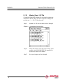
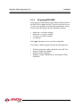
Sequence Tables Program
Reference Guide
Quality Assurance Program
Spartan Controls’ Quality Assurance Program guarantees the complete testing of all software.
To review the formal test documentation, or to report an error, please contact Spartan Controls’ Technical Manager.
Copyright Notice
Information in this manual is subject to change without notice.
© Copyright 2000 Spartan Controls Ltd. All rights reserved.
The contents of this publication are presented for informational purposes only, and while every effort has been made
to ensure its accuracy, it is not to be construed as warranties or guarantees, expressed or implied, regarding the
products or services described herein or its use or applicability. Spartan Controls reserves the right to modify or
improve the designs or specifications of such products or applications at anytime without notice.
Revision Level
Version 2.0, June 2000
Form ROCSeqTabMAN2.0
Contacting Spartan Controls Ltd.
Spartan Controls Ltd., 305 - 27 Street SE, Calgary, Alberta, Canada T2A 7V2
Phone: (403) 207-0700 Fax: (403) 207-0870 Website: www.spartan.ab.ca
Table of Contents
Chapter 1: Introduction .................................................................... 1
1.1 Program Enhancements ........................................................1
Chapter 2: Installation ...................................................................... 3
2.1 Downloading the Program ....................................................3
2.1.1Update Firmware .......................................................................4
2.1.2Altering Your .LST File ..............................................................6
2.1.3Preparing ROCLINK ..................................................................7
Chapter 3: Configuration .................................................................. 9
3.1 Sequence Table Functionality ..............................................16
Appendix A - Key Parameters ................................................................................A-1
This page is intentionally left blank.
Table of Figures
Changing a Directory Path ......................................................................................6
Spartan Menu in ROCLINK .....................................................................................9
Sequence Table Main Window ...............................................................................10
Multiple Tables Control Configuration Screen ........................................................14
Sequence Table - Single Table Example ................................................................16
Multiple Table Example (Test Table 1) ...................................................................17
Multiple Table Example (Test Table 2) ...................................................................17
Multiple Table Example (Test Table 3) ...................................................................18
Controls for Sequence Table 1 ...............................................................................18
Controls for Sequence Table 2 ...............................................................................19
Controls for Sequence Table 3 ...............................................................................19
This page is intentionally left blank.
Sequence Tables Program Ver. 2.0
About this Manual
About this Manual
This manual is a Reference Guide and is intended to be used
with the Field Automation Systems Type RL101 ROCLINK
Configuration Software User Manual. This manual provides a
basic overview of the Sequence Table User C Program, and
briefly describes how to download and configure the ROC 300
series of Remote Operation Controllers (ROCs) using
ROCLINKTM Configuration Interface Software.
This manual is divided into the following chapters:
Chapter 1: Introduction
Describes the program and lists the enhancements.
Chapter 2: Downloading the Program
Explains how to download the program into the ROC 300 series
using ROCLINK.
Chapter 3: Configuring the Program
Displays the ROCLINK screens and describes the parameters
of each screen.
Appendix A
Summarizes the key parameters.
i
About this Manual
Sequence Table Programs Ver. 2.1
Conventions
This manual practices the following conventions for word
usage and formatting standards.
Keywords
Select, Choose, Press,
or Click
Position the cursor on the toolbar
button or menu command and press
the left mouse button.
Left - Click
Press the left mouse button.
Right - Click
Press the right mouse button.
Double - Click
Quickly press the left mouse button
twice.
Format
ii
Action
Description
Bold
Bold text indicates a menu command or
a toolbar button.
Italics
Bold, italic text indicates a new term.
“Quotes”
Text in quotes is intended for you to
type or enter.
(Brackets)
Acronyms and abbreviations are placed
in brackets.
Annotations
Additional information will appear in the
side margins.
Sequence Tables Program Ver. 2.0
Introduction
Chapter 1: Introduction
The Sequence Tables User C Program enables the user to
configure a shutdown (SD) sequence. The program monitors
inputs such as fire and H2S sensors, and controls the outputs
such as fans, horns, and beacons.
1.1
Program Enhancements
•
A new field called First Tag was added next to the First
Table field. The First Tag field works similar to the First
Table field except instead of recording the Table number, it
records the Table tag.
•
In a earlier version of the Sequence Tables, the First Tag
field was already included, but in the newer version a feature to clear the First Tag was added. Now the First Tag
field is cleared when the First Table is zero and the test
results of the table are false.
•
The present version includes two ROC300 FlashPac files
and four files needed to upgrade the ROCLINK RL101
configuration software.
•
The program is now able to control the EU value of Analog
Outputs and Timed Discrete Outputs.
1
Introduction
Sequence Tables Program Ver. 2.0
This page is intentionally left blank.
2
Sequence Tables Program Ver. 2.0
Installation
Chapter 2: Installation
2.1
Downloading the Program
Fisher-Rosemount’s ROCLINK RL101 configuration software
version 2.11 or newer is used to download the program into a
ROC 312 or ROC 364 with a FLASHPAC firmware revision
2.10c or 2.11.
The two download files to choose from are described in the
following table.
Table 1: Download Files
Filename
Starting
Code
Block
# of
Blocks
Starting
Data
Block
# of
Blocks
Task
User
Defined
Points
Seqtbl3a.h00
C000
2
B800
2
USER 4
22
Seqtbl3b.h00
D800
2
A800
2
USER 4
22
When using a ROC300 series unit, load the User Programs from
a disk file into ROC user memory. Select User Programs
from the Utilities menu or File menu. When you select User
Programs, a display appears for viewing the unused memory
blocks.
3
Installation
Sequence Tables Program Ver. 2.0
2.1.1
Update Firmware
If the bios of your software doesn’t match the recommended
bios displayed in Table 1: Download Files, proceed with the
following firmware update procedure. The firmware can be
purchased from your local Fisher-Rosemount representative.
The Update Firmware option located under the File menu
allows you to update the internal software (stored in Flash
ROM) of a ROC or FloBoss by loading it in from a file. This
option does not update the ROCLINK software.
Note:
There is a possibility that the current configuration of the ROC
or FloBoss may be corrupted during the Update Firmware
procedure. Be sure to perform backups as instructed below.
4
Step 1.
The updated firmware files are typically supplied on
a diskette. It is recommended that you create a
backup copy of the firmware update disk.
Step 2.
Perform backups before proceeding. Save the
configuration to EEPROM and to disk. Save any
FSTs to disk as well.
Step 3.
Read the README.1ST text file included on the
firmware disk and follow the update instructions
given there.
Step 4.
Select Update Firmware from the File menu. The
Open File dialog box appears for specifying a File
Name to download. The Open File dialog displays
the names of all files with the .LST extension
located in the default directory.
Step 5.
Navigate to the location of the firmware file, such as
the A drive. You can change the path to the
directory containing the file using the Directory/
Sequence Tables Program Ver. 2.0
Installation
Drive field. If double-clicking the mouse doesn’t
work when selecting a different drive or directory,
use the Enter key.
Step 6.
Highlight the desired file in the Files list and press
OK. If you receive an error such as “File gas85.fsr
is missing or bad,” refer to Altering Your .LST File
below. The file begins loading, with the Status Line
showing the progress in four categories: Segment,
Address, Block Size, and Total Sent. While the
flash memory is being modified, the I/O is not read,
but is held at the last values.The loading process
typically takes several minutes; do not disturb it
during this time. If you are running ROCLINK
under Windows 95/98, then you can adjust the
miscellaneous properties of the ROCLINK window
to allow you to leave the window without
interrupting the download (Allow Screen Saver and
Always Suspend should not be checked, and Idle
Sensitivity should be set to Low).
Step 7.
When loading of the firmware is complete, the
action is recorded in the Event Log and a message
will appear on the message line saying that the ROC
has been successfully upgraded. Press Enter to
return to the ROCLINK menus You can verify the
upgrade by going to the Information screen
available from the System menu and using the
Revision Info pushbutton. If you disabled the Allow
Screen Saver and Always Suspend properties,
enable them again.
Step 8.
Perform a basic cold start to reload the configuration
from EEPROM. Check the configuration and FSTs;
if not correct, reload them from the disk files created
in Step 2.
5
Installation
Sequence Tables Program Ver. 2.0
2.1.2
Altering Your .LST File
If your ROCLINK.EXE program file is located in a directory
other than C:\ROCLINK, you will be required to change the
path in your .lst file. To alter the path:
Step 1.
Open the .lst file in a text editor such as Notepad.
Figure 11 - 1 Changing a Directory Path
6
Step 2.
Change the path to reflect the same location where
you have your ROCLINK.EXE file installed. Be
careful not to alter the file names.
Step 3.
Save your changes and exit Notepad.
Sequence Tables Program Ver. 2.0
Installation
2.1.3
Preparing ROCLINK
After you have installed the program, add the following files to
the ROCLINK working directory. These files allow the user to
view the screens and the associated help explanations, and are
located on the disk along with your installation software.
•
•
•
•
menu2.txt ( overwrites existing )
menu4.txt ( overwrites existing )
event.txt ( overwrites existing )
scl_sqtbl.tpl
Select yes if prompted to over write the existing file.
The Sequence Tables program includes the following items.
•
•
•
•
The files in the above tables, and the four listed PC files
Sequence Tables User Manual
Sequence Tables Worksheet
Example Customer Shutdown Key and Sequence Table
Worksheet
7
Installation
Sequence Tables Program Ver. 2.0
This page is intentionally left blank.
8
Sequence Tables Program Ver. 2.0
Configuration
Chapter 3: Configuration
Step 1.
Select Sequence Tables from the Spartan menu
(see Figure 3-1) in ROCLINK to open the Sequence
Tables Main Window (see Figure 3-2).
3
Figure 3 - 1 Spartan Menu in ROCLINK
1.
9
Configuration
Sequence Tables Program Ver. 2.0
Figure 3 - 2 Sequence Table Main Window
Figure 3-2 displays one of the Sequence Tables setup displays
(1 of 40). All tests being performed are configured in these
screens. There can be up to three parameters tested on each of
the 40 sequence tables, and the tables can be cascaded.
The sequence tables are executed continuously in groups of ten.
Once a group of ten has been executed, other user C programs
can run.
10
Sequence Tables Program Ver. 2.0
Configuration
The parameters of this screen are described in the following
table.
Parameters
Description
Tag
A 30 character tag that is used to describe the table.
Enable/Disabled
The enabled/disabled button is a toggle switch that controls
whether or not the table is active. Enabled means the table is
actively being tested; disabled means the table is dormant
unless it is called by another table. In a multiple table
sequence (cascaded tables), only the first table should be
enabled. The rest of the tables should be disabled.
Multiple Table Test
Result
“True” if the result of the multiple table test was true, “False”
otherwise. If either ‘Multiple Table Test Result’ or ‘Active
Table Test Result’ is true, there were no errors in the test
and the program does as much of the control as possible.
Active Table Test Result
“True” if the result of the current table’s test was true, “False”
otherwise. This field can tell you if any particular table in a
multiple table test is true or false. If either ‘Multiple Table
Test Result’ or ‘Active Table Test Result’ is true, there were
no errors in the test and the program does as much of the
control as possible.
Errors
Err 5”, Err 4”, Err 3” Err 2” Err 1” or Err 0” text boxes are
displayed if error is active, or hidden if there isn’t an error.
Only the first error encountered will have an error box
displayed. If either Multiple Table Test Result or Active Table
Test Result is true, then there were no errors in the test and
the program does as much of the control as possible.
Err 5
Visible if the Test Parameter does not point to a numeric
parameter, invisible otherwise.
Err 4
Visible if an incorrect comparison value has been entered, or
if any of the comparisons are not complete, invisible
otherwise.
Err 3
Visible if the comparison is greater than 10, and the Dynamic
Test Value does not point to a numeric parameter, invisible
otherwise.
Err 2
Visible if there is an error in any of the Operators, invisible
otherwise.
Err 1
Visible if there is no Control Parameter and the Control
Enable parameter says there should be one, or the Control
Parameter does not point to a numeric parameter, invisible
otherwise.
Err 0
Visible if there is no Dynamic Control Value and the Control
Enable is 11 or 12, or if the Dynamic Control Value does not
point to a numeric parameter, invisible otherwise.
Test Parameter
The Test Parameter points to the parameter to be used in the
test. If the table is enabled, the first Test Parameter must be
given. If an Operator is given, the Test Parameter on the
same line must be given. The Test Parameter must point to
a numeric parameter. The Test Parameters are to the right
of ‘Test 1’, ‘Test 2’, and ‘Test 3’ in Figure 3-2.
11
Configuration
Sequence Tables Program Ver. 2.0
Parameters
Comparison
Description
The Comparison is a number between 1 and 6 or 11 and 16,
which is used to tell the program how to compare the Test
Parameter and the Dynamic or Static Test Value. Below is a
description of the values of Comparison.
1 = greater than or equal (>=)
2 = greater than (>)
3 = not equal (<>)
4 = less than or equal (<=)
5 = less than (<)
6 = equal (=)
The above comparison values can be displayed in ROCLINK
if the button labeled ‘Cmp?’ is pressed.
If the Comparison is between 1 and 6, the program compares
the Test Parameter with the Static Test Value. By adding 10
to the Comparison, the program compares the Test
Parameter with the Dynamic Test Value instead. For
example, a Comparison of 11 will instruct the program to test
if the Test Parameter is greater than or equal to the Dynamic
Test Value.
The Comparisons are to the right of ‘Cmp1’, ‘Cmp2’, and
‘Cmp3’ in Figure 3-2
Dynamic Test Value
The Dynamic Test Value points to a numeric parameter that
is used in a comparison with the Test Parameter if the
Comparison is between 11 and 16.
The Dynamic Test Values are to the right of the Comparison
parameters in Figure 3-2.
Static Test Value
The Static Test Value is used in a comparison with the Test
Parameter if the Comparison is between 1 and 6.
The Static Test Values are to the right of the Dynamic Test
Values in Figure 3-2.
Operator
The Operator tells the program how to combine the tests. It
is a number between 1 and 3 and is described below.
1 = and
2 = or
3 = xor
The above operators can be displayed in ROCLINK by
pressing the button labeled ‘Op?’
If one of the first two Operators is given then the
corresponding Test Parameter, Comparison, and Dynamic or
Static Test Value must be given. If the last Operator is given,
the Table must be given also.
12
Sequence Tables Program Ver. 2.0
Configuration
Parameters
Table
Description
This parameter is used to make a multiple table test or
control. It can be any number less than or equal to 40, as
long as it is a greater number than the current table. When
creating multiple table tests, the cascaded tables must be
called in increasing order. Eg. table 10 can call table 15 but
not table 5.
If the Operator to the left of Table is given, the result of this
table is combined with the result of the table in Table. The
result of the multiple table test is shown in the ‘Multiple Table
Test Results’ field on the Sequence Table Setup screen.
The multiple table test continues to the table with no value in
the Operator to the left of Table.
If the Operator to the left of Table is not given and there is a
value in Table, the Controls on that table are done as well
(the tests, however, are not). The multiple table control
continues to the table, which does not have a value in Table.
All of the tables in a multiple table test or control should have
Enable set to 0 except the first one.
A table without tests can be cascaded by placing 0 in the OP
field to the left of the Table field and putting the number of
the Table in the Table field. If the multiple table test is true,
the controls configured in Multiple Tables will be executed.
This functionality is designed to allow the user to access
more controls if required.
The results of each of the tables in a multiple table test are
obtained first and then they are combined using the table
operators (ie. the Operator to the left of Table).
First Table
If the result of the test is true, the table number is written to
the parameter pointed to in First Table if it is zero. The
parameter must be numeric. In a multiple table test, the full
result (not those of any one table) is used, and only the First
Table on the first table of the multiple table test is used.
This parameter is optional. The First Table parameter is
located to the right of First Table in Figure 3-2.
Note: The First Table must be zeroed manually (eg. by one
of the controls in a sequence tables). It will never zeroed by
the program.
First Tag
If the table number is written to First Table as described
above, we write the tag of this table to the parameter pointed
to by First Tag. The parameter pointed to by First Tag must
be a 30 character string. Any of the Tag parameters in the
Sequence Tables or the FST message parameters can be
used.
This parameter is optional even if First Table is given. The
First Tag parameter is located to the right of First Tag in
Figure 3-2.
The First Tag is cleared when the First Table is zero and the
result of the test is false. Any control being performed by the
Sequence Tables is configured in the Multiple Table screens.
13
Configuration
Sequence Tables Program Ver. 2.0
Step 2.
Figure 3 - 3
Multiple Tables Control Configuration Screen
2.
14
Press Multiple Tables Control from the Sequence
Table main screen (see Figure 3-2) to display the
Multiple Tables Control Configuration screen (see
Figure 3-3). This screen is configured with static and
dynamic controls.
Sequence Tables Program Ver. 2.0
Configuration
The parameters of this screen are described in the following
table:
Parameters
Description
Control Enable
If this parameter is 1 and the result of the test is false, or if
this parameter is 2 and the result is true, then the Static
Control Value is written to the Control Parameter.
The Control Enable field is located to the left of ‘1.’ ‘2.’ … ,
’12.’ In Figure 3.3.
Eg. In Figure 3.3 if the result of the test is true, then a value
of 10 will be written to the Data1 parameter of Soft Point1. If
the result of the test is false, a value of zero will be written to
the Data1 Parameter of Soft Point1.
If the Control Enable parameter (the last two controls on the
bottom right side of the screen), is 11 and the result of the
test is false, or if the parameter is 12 and the result is true,
then the value of the parameter pointed to by the Dynamic
Control Value is written to the Control Parameter.
The Control Enable parameters are to the left of ‘1.’ ‘2.’ … ,
‘12’ in Figure 3.3.
Eg. In Figure 3.3 if the result of the test is true, then the
Filtered EU value of Analog Input A5 will be written to the
Data2 parameter of Soft Point1. If the result of the test is
false, then the Filtered EU value of Analog Input A5 will be
written to the Data3 parameter of Soft Point1.
Note: The result of the multiple table test is used on every
table and not the result of the table itself.
Control Parameter
Points to a numeric parameter. The Control Parameters are
to the right of ‘1.’ ‘2.’ … , ‘12’ in Figure 3-3.
Static Control Value
A value that is written to the Control Parameter depending on
the value of Control Enable and the result of the test.
These parameters are to the right of the ‘=’, and below the
Dynamic Control Value ( the last two controls on the right
side of the display in Figure 3-3.)
Dynamic Control Value
A pointer to a numeric parameter whose value is written to a
Control Parameter depending on the value of Control Enable
and the result of the test.
There are two of these parameters and they are to the right
of the ‘=’ beside the last two Control Parameters on the right
side of the display in Figure 3-3.
Single Table Test Example
A sample single table setup is shown below in Figure 3-4. In
this example the operators are evaluated as they appear on
this table.
15
Configuration
Sequence Tables Program Ver. 2.0
3.1
Sequence Table Functionality
The following screens are examples of multiple table tests and
controls.
The tests in the following table are evaluated as
[(SPT, 0,DATA1 = 0) or (SPT, 0,DATA2 = 0)] and (SPT,
0,DATA3 = 0).
Figure 3 - 4 Sequence Table - Single Table Example
16
Sequence Tables Program Ver. 2.0
Configuration
Figure 3 - 5 Multiple Table Example (Test Table 1)
Figure 3 - 6 Multiple Table Example (Test Table 2)
17
Configuration
Sequence Tables Program Ver. 2.0
Figure 3 - 7 Multiple Table Example (Test Table 3)
There are no tests configured on Table 3 (see Figure 3-7), but if
the Multiple Table Test is true, the controls configured in the
Multiple Tables will be executed.
Figure 3 - 8 Controls for Sequence Table 1
3.
If the result of the Multiple Table Test is true, a value of 1 will
be written to the Data4 parameter of Soft Point 1. If the result
18
Sequence Tables Program Ver. 2.0
Configuration
of the Multiple Table Test is false, a value of 0 will be written to
the Data4 parameter of Soft Point 1.
Figure 3 - 9 Controls for Sequence Table 2
4.
If the result of the Multiple Table Test is true, a value of 1 will
be written to the Data5 parameter of Soft Point 1. If the result
of the Multiple Table Test is false a value of 0 will be written to
the Data5 parameter of Soft Point 1.
Figure 3 - 10 Controls for Sequence Table 3
5.
If the result of the Multiple Table Test is true, a value of 1 will
be written to the Data5 parameter of Soft Point 1. If the result
19
Configuration
Sequence Tables Program Ver. 2.0
of the Multiple Table Test is false, a value of 0 will be written to
the Data5 parameter of Soft Point 1.
20
Sequence Tables Program Ver. 2.0
Appendix A - Key Parameters
Appendix A - Key Parameters
Status
Result Bits
Multiple Table Test Results - True if the result of the multiple
table test was true, False otherwise.
Active Table Test Results - True if the result of this table is true,
False otherwise.
Error Bits
Err 5 - error with one of the Test Parameters.
Err 4 - error in any of the Comparisons.
Err 3 - error with a Dynamic Test Value.
Err 2 - error in an Operator.
Err 1 - error in a Control Parameter.
Err 0 - error in one of the two Dynamic Control Value.
Comparison
1 = greater than or equal (>=)
2 = greater than (>)
3 = not equal (<>)
4 = less than or equal (<=)
5 = less than (<)
6 = equal (=)
Add 10 to the Comparison to make it dynamic.
Operator
1 = and
2 = or
3 = xor
A-1
Appendix A - Key Parameters
Sequence Tables Program Ver. 2.0
Control Enable
1 = do the control if the test was FALSE
2 = do the control if the test was TRUE
On the last two Controls add 10 to the Control Enable to use the
Dynamic Control Value instead of the Static Control Value.
A- 2