1
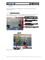
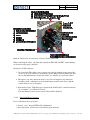
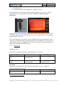
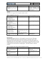
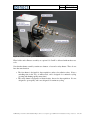
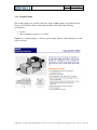
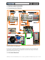
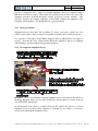
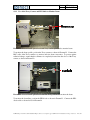
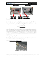
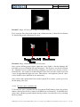
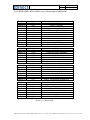
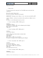
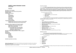
GeniX
Installation and Operation Manual
Version 005
Date
July 5, 2007
TABLE OF CONTENTS
GENIX ............................................................................................................................................................... 1
1
SAFETY: RISKS AND PRECAUTIONS .......................................................................................................... 6
1.1
1.1.1
1.1.2
1.2
1.2.1
1.2.2
1.3
1.3.1
1.3.2
1.4
1.5
ELECTRICAL .............................................................................................................................................. 6
Risks................................................................................................................................................. 6
Precautions ...................................................................................................................................... 6
RADIATION PROTECTION ............................................................................................................................ 6
Risks................................................................................................................................................. 7
Precautions ...................................................................................................................................... 7
CHEMICAL HAZARDS .................................................................................................................................. 7
Risks................................................................................................................................................. 7
Precautions ...................................................................................................................................... 7
OTHER HAZARDS ...................................................................................................................................... 8
ENVIRONMENTAL POLICY............................................................................................................................ 8
2
WARRANTY ............................................................................................................................................. 9
3
TECHNICAL DESCRIPTION OF GENIX ...................................................................................................... 10
3.1
THEORY OF X-RAY OPTICS ......................................................................................................................... 10
3.2
COMPONENTS OF GENIX .......................................................................................................................... 12
3.2.1
Integration conditions in your installation .................................................................................... 12
3.2.1.1
3.2.1.2
3.2.1.3
3.2.1.3.1
3.2.1.3.2
3.2.1.3.3
3.2.2
Control Unit ................................................................................................................................... 14
3.2.2.1
3.2.2.2
3.2.2.3
3.2.2.4
3.2.2.5
3.2.2.6
3.2.2.7
3.2.2.8
3.2.3
3.2.4
3.2.5
4
Components ........................................................................................................................................ 12
Size of the system ................................................................................................................................ 13
Connections to foresee ....................................................................................................................... 13
Electrical connections .......................................................................................................................... 13
Water connections .............................................................................................................................. 13
Vacuum connection............................................................................................................................. 13
Interface Buttons ................................................................................................................................. 15
Expert mode ........................................................................................................................................ 15
Controller Details – back side .............................................................................................................. 16
Interlock Failure Correction ................................................................................................................. 17
Interlock list ......................................................................................................................................... 18
Cold Start Procedure ........................................................................................................................... 21
Starting From Standby ......................................................................................................................... 22
Stop Procedure .................................................................................................................................... 22
Optical Head .................................................................................................................................. 22
Roughing Pump ............................................................................................................................. 24
Chiller ............................................................................................................................................ 25
INSTALLATION OF GENIX ....................................................................................................................... 26
4.1
CONNECTION OF ALL ELEMENTS ................................................................................................................ 26
4.2
ALIGNMENT PROCEDURE .......................................................................................................................... 26
4.2.1
Safety precautions ......................................................................................................................... 27
4.2.2
Description of Alignment Screws ................................................................................................... 27
4.2.3
Use of the X-ray Camera and PIN-diode to Monitor Beam ........................................................... 28
4.2.4
Optimizing the X-ray Beam ........................................................................................................... 29
4.2.4.1
4.2.4.2
Verify X-ray beam with X-ray camera .................................................................................................. 29
Fine tune optic to maximize flux ......................................................................................................... 31
Z:\Marketing & Commercial\Produits\GeniX\procédures et description appareil\DDV-071107-installation and
operation.doc
2 /38
Version 005
Date
July 5, 2007
4.2.4.3
4.2.4.4
4.3
Confirm alignment with X-ray camera................................................................................................. 32
Precise alignment with a pinhole ........................................................................................................ 32
REMOTE CONTROL .................................................................................................................................. 33
Z:\Marketing & Commercial\Produits\GeniX\procédures et description appareil\DDV-071107-installation and
operation.doc
3 /38
Version 005
Date
July 5, 2007
TABLE OF FIGURES
Figure 1 : Icon indicating the presence of electrical hazards. ...................................................6
Figure 2 : Icon indicating the presence of radiation hazards. ...................................................6
Figure 3 : Icon indicating the presence of chemical hazards. ...................................................7
Figure 4 : Icon indicating general hazard. ...............................................................................8
Figure 5 : Typical reflectivity curve of a W/Si multilayer optic designed to match Cu Kα
emission lines. ......................................................................................................................10
Figure 6 : Ellipsoidal mirror with lengths p and q indicated. This schematic represents the
focusing case. For a collimating mirror with q = ∞ we would get a parallel beam, and the
ellipsoid of revolution would be a parabaloid of revolution. ..................................................11
Figure 7 : GeniX head (in back) and control unit (in front). Remote indicator box is shown at
right......................................................................................................................................12
Figure 8 : Chiller for GeniX system. .....................................................................................12
Figure 9 : Dry pump for GeniX system. ................................................................................12
Figure 10 : Front panel of GeniX control unit and the remote status box. .............................14
Figure 11 : Left side of control unit front panel, with components marked. ...........................14
Figure 12 : Right side of control unit front panel, with components marked. Note that for the
two keys, vertical is off, horizontal is on. ..............................................................................15
Figure 13 : The user interface touch-screen with the menu buttons functions indicated. ........15
Figure 14 : Detail of back side of GeniX control unit. ...........................................................16
Figure 15 : Detail of back side of GeniX control unit. ...........................................................16
Figure 16 : Detail view of connections on back of Genix control unit. ..................................17
Figure 17 : View of interlock LED and interlock screen after interlocks have been closed and
“ACQUIT” button pressed. Note interlock screen color is orange instead of red, indicating
that all interlocks are closed. .................................................................................................18
Figure 18 : View of the introduction screen (left) and the automatic mode screen (right). .....22
Figure 19 : View of GeniX optical head................................................................................23
FIGURE 20 : Diagram showing the connections for the various GeniX units (optical head,
control unit, chiller, and vacuum pump)................................................................................26
FIGURE 21 : View of opto-mechanics showing alignment screws. Note that one tilt and one of
the Bragg alignment screws are not visible in the photo because there are located on the far
side of the GeniX optical head. .............................................................................................27
FIGURE 22 : View of GeniX optical head with X-ray camera positioned to monitor beam. .....28
FIGURE 23 : View of GeniX optical head with PIN-diode positioned to monitor the beam. ....28
FIGURE 25 : View of front and back of PIN-diode. ................................................................29
FIGURE 26 : View of collimator tube. ....................................................................................29
FIGURE 27 : View of Bragg and tilt adjustment screws on GeniX optical head. ......................30
FIGURE 28 : Image of X-ray beam at output of collimator mount. ..........................................31
FIGURE 29 : Image of diffracted and direct X-ray beams........................................................31
FIGURE 30 : View of the collimator tube and the pinhole mount. ...........................................32
FIGURE 31 : input / output for software development .............................................................35
FIGURE 32 : software words ..................................................................................................36
Z:\Marketing & Commercial\Produits\GeniX\procédures et description appareil\DDV-071107-installation and
operation.doc
4 /38
Version 005
Date
July 5, 2007
Dear Customer,
Welcome to the GeniX Installation and Operation Manual. This manual provides operational
instructions for the GeniX Beam Delivery System. Please read it thoroughly before using this
equipment.
The GeniX Beam Delivery System is a standard component in many analytical instruments.
It is also available as a “stand-alone” item for use by academic or industrial research
organizations.
The GeniX Beam Delivery System is designed to be simple to set up and operate. However,
should you encounter any problems that are not addressed by this manual, please contact the
Technical Support Department of Xenocs at the address below.
XENOCS SA
19, rue François Blumet
F-38 360 Sassenage
FRANCE
Tel: + 33 (0)4 76 26 95 40
Fax: + 33 (0)4 76 26 95 49
Email: [email protected]
Web: www.xenocs.com
Z:\Marketing & Commercial\Produits\GeniX\procédures et description appareil\DDV-071107-installation and operation.doc 5 /38
Version 005
Date
July 5, 2007
1 SAFETY: RISKS AND PRECAUTIONS
1.1 ELECTRICAL
1.1.1
Risks
The GeniX control unit contains voltages high enough to cause sever injury to persons,
including heart failure, respiratory failure, or severe burning. Under no circumstances should
unauthorized personnel open the control unit.
Figure 1
: Icon indicating the presence of electrical hazards.
The GeniX system is designed to meet the safety requirements of EC/UL norms. The areas
presenting potential electrical hazards are clearly labeled with the icon in Erreur ! Source du
renvoi introuvable.. These areas may contain the voltages listed below:
• High voltage ( > 10 kV DC)
• Medium voltage (100 - 250 V AC)
• Low voltage (24 Volts DC)
1.1.2 Precautions
By default, the GeniX should be powered off completely and unplugged from the wall socket
before performing any maintenance or repair work. If power must be maintained to perform a
particular maintenance or repair task, several important rules should be respected:
• Only authorized persons are to perform maintenance or repair tasks, in compliance
with all local laws and regulations. (French law: C18 510; 14/12/1988).
• If performing maintenance or repair tasks with the GeniX connected to a power outlet,
maintenance personnel should wear individual protection equipment such as 1000 V
insulating gloves and safety glass with UV filter. This list is non-exhaustive – consult
local safety authorities for full protection measures to be taken.
1.2 RADIATION PROTECTION
Figure 2 :
Icon indicating the presence of radiation hazards.
Z:\Marketing & Commercial\Produits\GeniX\procédures et description appareil\DDV-071107-installation and operation.doc 6 /38
Version 005
Date
July 5, 2007
1.2.1 Risks
X-ray photons constitute ionizing radiation, which could lead to significant injury to humans
or other biological systems. The main consequence of over-exposure is a drastic increase in
the risk of leukemia or cancer. The legal exposure limits are determined by the local radiation
safety authorities.
1.2.2 Precautions
The GeniX system is certified by an independent radiation safety organization accredited by
the French government to emit a dose lower than 1 µSv/h at any point no closer than 10 cm to
the GeniX head, excepting of course the exit point of the X-ray beam. However, this in no
way diminishes the responsibility of the user in case of misuse of the instrument.
For maintenance tasks (e.g. adjusting the optics, aligning the X-ray beam with other
equipment…) that oblige persons to work without the benefit of the complete safety protocol
several rules should be respected:
• Only authorized persons should be allowed to perform such tasks. It is the user’s
responsibility to check with the local radiation safety authorities and to follow all
applicable laws and regulations.
• The end of collimator has to perfectly block with adapted piece (made in lead).
• Check with a Geiger-Müller detector (Xenocs recommends Fujifilm Inspector) that the
efficient dose flux is lower than 1µSv/h at a distance of 10 cm around the system.
• If you suspect a leak, contact your local radiation protection officer for assistance.
1.3 CHEMICAL HAZARDS
Figure 3 :
Icon indicating the presence of chemical hazards.
1.3.1 Risks
The X-ray tube has a beryllium window. The dust and vapor of beryllium are very toxic if
inhaled or ingested. Xenocs therefore recommends the following precautions:
1.3.2 Precautions
• Do not touch the Be window with bare hands.
• Do not clean the Be window with any chemical products.
Z:\Marketing & Commercial\Produits\GeniX\procédures et description appareil\DDV-071107-installation and operation.doc 7 /38
Version 005
Date
July 5, 2007
• Maintenance persons should wear appropriate safety glasses and gloves when
manipulating the X-ray tube.
• Do not dismantle the X-ray tube
• Return damaged tubes in adapted packaging to Xenocs (contact Xenocs Technical
Support Department for more information).
1.4 OTHER HAZARDS
Figure 4 :
Icon indicating general hazard.
There are a number of other hazards present in the Genix, including (but not limited to) the
following:
• Water chiller contain a number of potentially hazardous features includes hot or cold
plates, compressed gases, and moving mechanical parts (e.g. in recirculating pump).
• Safety precautions must be taken when moving the heavy components such as chiller,
GeniX controller or GeniX head.
• If in doubt regarding the safety of any procedure, feel free to contact Xenocs Technical
Support Department for assistance (note that contacting Xenocs does not free the user
from the obligation to follow all applicable laws and regulations).
1.5 ENVIRONMENTAL POLICY
The design of GeniX is made to meet the requirements of European standards such as the
RoHS rules. The materials used for the construction of GeniX system, such as stainless steel
or brass, are recyclable. Due to beryllium parts, the X-ray tube should not be discarded in
conventional waste. Please return all undesired X-ray tubes to Xenocs for disposal.
Z:\Marketing & Commercial\Produits\GeniX\procédures et description appareil\DDV-071107-installation and operation.doc 8 /38
Version 005
Date
July 5, 2007
2 WARRANTY
The standard warranty period is one (1) year from the date of acceptance of the GeniX.
The warranty is limited to either repair or replacement of the relevant part, to be decided by
Xenocs. If Xenocs deems that a return of defective item(s) to Xenocs is necessary, the
shipment of said items shall be paid for by Xenocs.
The warranty does not apply if the defect is caused by:
• normal wear and tear;
• improper use (as determined by Xenocs), including but not limited to the use of the
GeniX with interlocks defeated
• use of the GeniX in an environment at variance with the environment described in the
user's manual;
• modification of the GeniX that has not been approved by XENOCS in written form.
Z:\Marketing & Commercial\Produits\GeniX\procédures et description appareil\DDV-071107-installation and operation.doc 9 /38
Version 005
Date
July 5, 2007
3 TECHNICAL DESCRIPTION OF GENIX
3.1 THEORY OF X-RAY OPTICS
The Xenocs FOX optics use the principle of Bragg diffraction to reflect X-rays. A multilayer
coating assures constructive interference of the reflected rays, as described by Bragg’s law.
Since only rays satisfying Bragg’s law are reflected, a multilayer coating also serves as a
natural band-pass filter. The thickness of the individual layers in the multilayer stack are
chosen so that only the Kα lines (Cu Kα, Mo Kα – depending on design) are reflected, whereas
the other energies are strongly absorbed (see Erreur ! Source du renvoi introuvable.).
Multilayer reflectivity and Cu emission lines
0.8
multilayer reflectivity
Cu lines
0.7
Reflectivity R
0.6
0.5
0.4
0.3
0.2
kα 1
kβ
0.1
kα 2
0.0
6
7
8
9
10
energy E [keV]
Figure 5 : Typical
reflectivity curve of a W/Si multilayer optic designed to match Cu Kα
emission lines.
The geometrical shape of the mirror is that of a section of an ellipsoid of revolution (or a
paraboloid of revolution for a collimating mirror) as shown in Erreur ! Source du renvoi
introuvable.. With this shape, each ray coming from the left focus (the source) will pass
through the right focus (the image). For extended sources (when the source may not be
approximated as a point), the image size will be proportional to the source size. The length of
Z:\Marketing & Commercial\Produits\GeniX\procédures et description appareil\DDV-071107-installation and operation.doc 10 /38
Version 005
Date
July 5, 2007
the mirror and the useful width is defined to optimize flux while keeping a reasonably low
divergence.
Ellipsoidal mirror with lengths p and q indicated. This schematic represents the
focusing case. For a collimating mirror with q = ∞ we would get a parallel beam, and the
ellipsoid of revolution would be a parabaloid of revolution.
Figure 6 :
Because the incident angle of X-rays coming from the source varies along the length of the
mirror, the multilayer coating thickness must be graded longitudinally so that the Bragg
condition is met at each point of the mirror.
This patented design has several advantages over the other X-ray focusing/collimating
systems:
•
Xenocs’ FOX optics collect more flux than double reflection mirrors,
•
They are wavelength selective bandpass filters (they yield monochromatic radiation),
•
They have higher average reflectivities due to the single-reflection,
•
They are very easy to align because only one reflection is involved.
•
Due to larger flux collection angles, they produce more stable X-ray beams
Z:\Marketing & Commercial\Produits\GeniX\procédures et description appareil\DDV-071107-installation and operation.doc 11 /38
Version 005
Date
July 5, 2007
3.2 COMPONENTS OF GENIX
3.2.1 Integration conditions in your installation
3.2.1.1 Components
The GeniX system consists of 4 components: 1) the GeniX head, 2) the control unit, 3) the
chiller, and 4) the vacuum pump – see photos below.
Figure 7 :
GeniX head (in back) and control unit (in front). Remote indicator box is shown at
right.
Figure 8 :
Chiller for GeniX system.
Figure 9 :
Dry pump for GeniX system.
Z:\Marketing & Commercial\Produits\GeniX\procédures et description appareil\DDV-071107-installation and operation.doc 12 /38
Version 005
Date
July 5, 2007
3.2.1.2 Size of the system
The control unit and the chiller can be placed in 3U racks. If you do not have such
installation to receive systems, the following conditions must be respected:
1. A free space above and under each element is necessary particularly if the covers
are not perforated.
2. The space behind each unit must be at least 15 cm to allow proper ventilation of
the system.
The space required to accommodate the GeniX head depends on the mirror type purchased.
For the larger versions, at least 600 mm horizontal space is needed. This space includes that
needed for proper connection of the cooling water hoses. The height of the GeniX head is
330 mm, and the width is 200 mm.
The pump measures 32 X 15 X 15 cm3, and should be placed on the floor to absorb vibrations
(which are very minor).
3.2.1.3 Connections to foresee
3.2.1.3.1 Electrical connections
With the system completely installed, you will use 5 power connections – one for each of the
following items:
1.
2.
3.
4.
5.
the control unit
the chiller
the pump
the MAR CAM
the pindiode.
3.2.1.3.2 Water connections
In the event that you did not purchase a chiller from Xenocs, the outside diameter of hose that
connects the chiller to the GeniX head is 6 mm. If your water hoses are different dimensions,
you must provide the appropriate adaptors to enable Xenocs to complete the installation.
3.2.1.3.3 Vacuum connection
In the event that you did not purchase the vacuum pump from Xenocs, the outside diameter of
the vacuum tube that connects the pump to the GeniX head is 4 mm. If your vacuum tubes
are different dimensions, you must provide the appropriate adaptors to enable Xenocs to
complete the installation.
Z:\Marketing & Commercial\Produits\GeniX\procédures et description appareil\DDV-071107-installation and operation.doc 13 /38
Version 005
Date
July 5, 2007
3.2.2 Control Unit
Figure 10 :
Front panel of GeniX control unit and the remote status box.
Figure 11 :
Left side of control unit front panel, with components marked.
Z:\Marketing & Commercial\Produits\GeniX\procédures et description appareil\DDV-071107-installation and operation.doc 14 /38
Version 005
Date
July 5, 2007
Right side of control unit front panel, with components marked. Note that for the
two keys, vertical is off, horizontal is on.
Figure 12 :
3.2.2.1 Interface Buttons
Figure 13 :
The user interface touch-screen with the menu buttons functions indicated.
3.2.2.2 Expert mode
Expert mode is only to be used by authorized personnel, as defined by the local radiation
safety authorities. Under no circumstances should the GeniX be operated in expert mode by
unqualified personnel.
If it is necessary to operate the GeniX with the interlocks defeated, for example to align the
optics, it is possible using the expert mode. To place the GeniX in expert mode, simply insert
the expert mode key and turn it to the horizontal position (see Erreur ! Source du renvoi
introuvable. below). The touch screen will flash red, and the GeniX will emit a periodic
audible signal. With the GeniX in this mode, it is possible to operate the GeniX with the
following interlocks defeated.
1. Door interlock
2. Cover protection
Z:\Marketing & Commercial\Produits\GeniX\procédures et description appareil\DDV-071107-installation and operation.doc 15 /38
Version 005
Date
July 5, 2007
3. Vacuum
4. Red lamps
This mode is manually chosen by turning the key located on the back of the controller as
shown on figure 13.
3.2.2.3 Controller Details – back side
The following figures show the connections for the back side of the GeniX control unit. Note
that all connections are unique, so it is not possible to improperly connect the cables.
Figure 14 :
Detail of back side of GeniX control unit.
Figure 15 :
Detail of back side of GeniX control unit.
Z:\Marketing & Commercial\Produits\GeniX\procédures et description appareil\DDV-071107-installation and operation.doc 16 /38
Version 005
Date
July 5, 2007
Figure 16 :
Detail view of connections on back of Genix control unit.
When connecting the cables, especially the connections X03, X05, and X07, ensure that they
are securely and properly connected.
Description of X03 connector:
1. Door interlock: This enables you to ensure your safety by shutting down power if the
doors to your X-ray cabinet are accidentally opened. When system is installed we will
ask you the authorization to bypass this safety or to install it on your X-ray cabinet.
2. Emergency stop: this connection allows you to wire an emergency stop button far
from the system, so that the user can keep this button near the work area to shut the
system down in case of emergency.
3. Remote/Local pins: With these pins connected, the GeniX can be controlled remotely
via a computer. (cf 4.3 Remote Control)
Note that manual (touch-screen) control of the GeniX is disabled.
3.2.2.4
Interlock Failure Correction
If one of the interlocks is open, then
1. the red “error” interlock LED will be illuminated;
2. the touch screen will become red and list the open interlocks
Z:\Marketing & Commercial\Produits\GeniX\procédures et description appareil\DDV-071107-installation and operation.doc 17 /38
Version 005
Date
July 5, 2007
3. correct the fault
4. reset the fault on the list by pushing the “ACQUIT“ button
If all interlocks are closed, the green interlock LED will indicate system is “ok”, and the
display will become orange again, as shown below in Erreur ! Source du renvoi
introuvable..
View of interlock LED and interlock screen after interlocks have been closed and
“ACQUIT” button pressed. Note interlock screen color is orange instead of red, indicating
that all interlocks are closed.
Figure 17 :
If one of the interlocks is not properly corrected, then the touch screen will remain red, the
interlock error LED will remain on, and the GeniX will not be authorized to produce X-rays.
Only when the user has successfully closed all interlocks will the system become functional
again (after pushing the “ACQUIT” button).
3.2.2.5 Interlock list
Tube Temperature
This interlock is triggered if the X-ray tube temperature exceeds 45 °C.
Initial GeniX State
GeniX operating in normal
mode1
Action
Any action increasing the
tube temperature
Affect on GeniX State
X-ray tube high voltage shut
off
GeniX operating in expert
mode
Any action increasing the
tube temperature
X-ray tube high voltage shut
off after 10 seconds
Red Lamp
This interlock is triggered if the red safety bulb in the remote status box is damaged.
Table 1: Red lamp interlock state table.
Initial GeniX State
GeniX operating in normal
mode
1
Action
Red bulb is broken
Affect on GeniX State
X-ray tube high voltage shut
off
i.e. not expert mode (see § 3.2.2.22)
Z:\Marketing & Commercial\Produits\GeniX\procédures et description appareil\DDV-071107-installation and operation.doc 18 /38
Version 005
Date
July 5, 2007
•
•
GeniX operating in expert Red bulb is broken
mode
Shutters open or closed
Nothing happens: system
functions
normally
and
operations can be dangerous
for the operator.
Vacuum
This interlock is triggered if the beampath vacuum is broken.
Table 2: Vacuum interlock state table.
Initial GeniX State
• GeniX operating in
normal mode
• Collimator and cap
mounted on mirror
• GeniX operating in
normal mode
• Collimator mounted on
mirror
• GeniX operating in
normal mode
• Mirror and collimator
under vacuum
• GeniX in normal mode,
but not started
• Mirror mounted
Action
Vacuum broken
Affect on GeniX State
X-ray tube high voltage shut
off
Cap removed
X-ray tube high voltage shut
off
Cap and collimator removed
X-ray tube high voltage shut
off
Vacuum tube connected
directly between sensor and
mirror
GeniX control unit started
GeniX operating in expert Vacuum broken
mode
Nothing happens
Nothing happens
Door Interlock
This interlock is triggered if the door of X-ray hutch is not properly closed. The wiring
external to the GeniX control unit for this interlock must be connected by the user. The
functioning of this interlock depends on the state of the interlock and the safety shutter (it is
independent of the state of the fast shutter), as shown below. Note that the first table is for the
GeniX operating in normal mode, the second for the GeniX operating in expert mode. For all
combinations not noted in the tables, nothing happens – the GeniX continues to function
normally.
Table 3 : Door interlock state table for GeniX operating in normal mode.
Initial GeniX State
• Safety shutter open
• X-ray enclosure doors
closed
• Safety shutter closed
• X-ray enclosure doors
closed
• Safety shutter closed
Action
Affect on GeniX State
Open door of X-ray enclosure • X-ray tube high voltage
shut off
• Safety Shutter closes
Open door of X-ray enclosure Nothing happens: system is
safe
Attempt to open safety
• Safety shutter will not
Z:\Marketing & Commercial\Produits\GeniX\procédures et description appareil\DDV-071107-installation and operation.doc 19 /38
Version 005
Date
July 5, 2007
•
X-ray enclosure doors
open
shutter
open
• X-ray tube high voltage
NOT shut down
• GeniX state unchanged
Table 4: Door interlock state table for GeniX operating in expert mode.
Initial GeniX State
• Safety shutter open
• X-ray enclosure doors
closed
•
•
•
•
Safety shutter closed
X-ray enclosure doors
closed
Safety shutter closed
X-ray enclosure doors
open
Action
Affect on GeniX State
Open door of X-ray enclosure • Green LED blinks on
remote indicator box
• “Door opened” displayed
on control unit screen
Open door of X-ray enclosure Nothing happens: system is
safe
Open safety shutter
• Safety shutter does not
open
• Green LED blinks on
remote indicator box
• “Door opened” displayed
on control unit screen
Water Flow
This interlock is triggered if there is improper water flow in the cooling system.
Table 5: Water flox interlock state table.
Initial GeniX State
GeniX operating in normal
mode
GeniX operating in expert
mode
Action
Any action decreasing water
flow under 1,2 L/min
Any action decreasing water
flow under 1,2 L/min
Affect on GeniX State
X-ray tube high voltage shut
off
X-ray tube high voltage shut
off
Safety Shutter Interlock
Switches off the power if safety shutter is not confirmed to be in the expected position (note
that the expected position may be either open or closed). Note that this interlock does not
check the state of the fast shutter state. Indeed this shutter is not a safety element but is
only to facilitate measurements.
Table 6: Shutter interlock state table.
Initial GeniX State
• GeniX operating in
normal mode
• Safety shutter open or
closed
Action
Push safety shutter button
• GeniX operating in expert Push safety shutter button
mode
Affect on GeniX State
If the state of the shutter is
not detected for > 1 second,
the X-ray high voltage is
shut off
Nothing happens
Z:\Marketing & Commercial\Produits\GeniX\procédures et description appareil\DDV-071107-installation and operation.doc 20 /38
Version 005
Date
July 5, 2007
• Safety shutter open or
closed
Cover protection
Switches off the power if the cover is not in position.
Initial GeniX State
1. GeniX operating normal
mode2
2. Cover protection on the
GeniX
1. GeniX operating in
expert mode
2. Cover protection on the
GeniX
Action
Removing this cover
Removing this cover
Changes in GeniX State
1. X-ray tube high voltage
shut off
1. Nothing happens. In this
case safety of users can
be not ensure by GeniX.
3.2.2.6 Cold Start Procedure
1. Verify that the Emergency Shut-Off button is in the extended position.
2. Switch the main power on by pushing in the green button on the left side of the control
unit front panel.
3. After few seconds, the green interlock ok LED should light, indicating that all
interlocks are ok.
4. Press the arrow on the screen to go to the “automatic mode” screen, or press the R1
menu button.
5. Turn the XRAY ON key to horizontal. The red x-ray on lamp should light.
6. Turn the STANDBY key to horizontal, and wait while the GeniX ramps up the voltage
and current to the standby level. (30 kV, 0.4 mA).
7. When the the GeniX reaches standby power, wait a few minutes, then turn the
STANDBY key to off (vertical).
8. Press the START CYCLE button on the touch screen, and wait while the GeniX
automatically ramps up to the nominal power. Normally, nominal power is full power
(50 kV, 1 mA), but it may be configured by the user. If your nominal power is not the
power desired, enter the configuration screen (R4) and enter your desired nominal
power settings.
9. Once nominal power is reached, the GeniX is ready for use.
2
i.e. not expert mode (see § 3.2.2.22)
Z:\Marketing & Commercial\Produits\GeniX\procédures et description appareil\DDV-071107-installation and operation.doc 21 /38
Version 005
Date
July 5, 2007
Figure 18 :
View of the introduction screen (left) and the automatic mode screen (right).
3.2.2.7 Starting From Standby
To bring the GeniX up to nominal power from standby, simply execute the instructions given
above for cold-starting beginning at step 7.
3.2.2.8 Stop Procedure
1. Verify that both the safety and the fast shutter are closed.
2. Turn the STANDBY key to on (horizontal).
3. Wait for the GeniX to ramp down to the standby power.
4. Turn the STANDBY key to OFF (vertical).
5. Go to the manual screen of the touch screen (R5)
6. Reduce the current to zero.
7. Reduce the voltage to zero.
IMPORTANT
The current must be reduced to zero before the voltage is decreased below 10 kV, otherwise
the source could be destroyed.
8. Turn the XRAY ON key to off (vertical)
9. Switch off the main power by pushing in the power off button on the left of the control
unit front panel (see Erreur ! Source du renvoi introuvable.).
10. Let the water chiller run for a few minutes to evacuate the residual heat from the
GeniX head.
3.2.3 Optical Head
Z:\Marketing & Commercial\Produits\GeniX\procédures et description appareil\DDV-071107-installation and operation.doc 22 /38
Version 005
Date
July 5, 2007
Figure 19 :
View of GeniX optical head.
Filter holder and collimator assembly are optional. So GeniX is delivered without these two
tools.
Note that the shutter assembly contains two shutters: a fast and a safety shutter. These do not
have the same function.
• The fast shutter is designed for data acquisition, and not for radiation safety. It has a
switching time in the 10’s of milliseconds, and is designed for continuous cycling
(opening and shutting rapidly many times).
• The safety shutter is designed for radiation safety, but not for data acquisition. It is not
designed to open rapidly, and is not designed for continuous cycling.
Z:\Marketing & Commercial\Produits\GeniX\procédures et description appareil\DDV-071107-installation and operation.doc 23 /38
Version 005
Date
July 5, 2007
3.2.4 Roughing Pump
The roughing pump is an optional component If the roughing pump is not purchased from
Xenocs, care should be taken to ensure that the chiller used respects the following
specifications:
• Oil free;
• Able to maintain a pressure of ≤ 1 mbar.
Furthermore, vacuum fittings to connect to plastic tubing with an outside diameter of 4 mm
will be necessary.
Z:\Marketing & Commercial\Produits\GeniX\procédures et description appareil\DDV-071107-installation and operation.doc 24 /38
Version 005
Date
July 5, 2007
3.2.5 Chiller
The chiller is an optional component. If the chiller is not purchased from Xenocs, care should
be taken to ensure that the chiller used respects the following specifications:
• A flow rate of 1.2 L/min in GeniX head;
• A stable temperature of 25°C in GeniX head.
Furthermore, fittings to connect to plastic tubing with an outside diameter of 6 mm will be
necessary.
The chiller may be filled using normal tap water. However, it is advised to add an anti-algae
solution to avoid algae buildup, notably in the filter. In addition, it is advised to change the
water completely and wash the filter if necessary approximately once per month. The drain is
located under the front right corner of the chiller.
Z:\Marketing & Commercial\Produits\GeniX\procédures et description appareil\DDV-071107-installation and operation.doc 25 /38
Version 005
Date
July 5, 2007
4 INSTALLATION OF GENIX
4.1 CONNECTION OF ALL ELEMENTS
FIGURE 20 : Diagram showing the connections for the various GeniX units (optical head,
control unit, chiller, and vacuum pump).
Do not forget to connect the ground to the optical head, control unit, and to the ground of the
bench where system is placed. It is very important to ensure the same voltage on all of these
points to prevent a risk of over-voltage.
4.2 ALIGNMENT PROCEDURE
Z:\Marketing & Commercial\Produits\GeniX\procédures et description appareil\DDV-071107-installation and operation.doc 26 /38
Version 005
Date
July 5, 2007
For ease of alignment, and to ensure an optimum alignment, Xenocs recommends using a
PIN-diode and an X-ray camera. These items may be purchased from Xenocs if needed. The
alignment procedure described hereunder assumes procession of these elements. This
procedure describes the complete alignment of the GeniX, including the alignment of the
collimator and the pinholes, even though these are optional elements.
4.2.1 Safety precautions
Alignment must be done under safe conditions. To ensure your safety, consult your local
radiation safety officer. Xenocs cannot be responsible for injuries due to radiation exposure.
It is advised to work with a Geiger Müller radiation detector, which Xenocs can supply if
need be. Note that the X-ray camera and the PIN-diode supplied by Xenocs are equipped
with shielding to prevent radiation leakage under normal use.
4.2.2 Description of Alignment Screws
FIGURE 21 : View of opto-mechanics showing alignment screws. Note that one tilt and one of
the Bragg alignment screws are not visible in the photo because there are located on the far
side of the GeniX optical head.
On all alignment screws there is a small lock-screw that enables the operator to lock the
alignment screws in position when alignment is optimum. Do not forget to loosen these
screws before adjusting the alignment screws.
Z:\Marketing & Commercial\Produits\GeniX\procédures et description appareil\DDV-071107-installation and operation.doc 27 /38
Version 005
Date
July 5, 2007
4.2.3 Use of the X-ray Camera and PIN-diode to Monitor Beam
FIGURE 22 : View of GeniX optical head with X-ray camera positioned to monitor beam.
To monitor the beam profile, position the X-ray camera as shown in FIGURE 22. Connect the
BNC cable of the X-ray camera to a monitor and view beam on monitor. To protect against
radiation leakage, ensure that the collimator is completely inserted into the sleeve of the X-ray
camera, as shown in FIGURE 22.
FIGURE 23 : View of GeniX optical head with PIN-diode positioned to monitor the beam.
To monitor the beam flux, position the PIN-diode as shown in FIGURE 23. Connect the PINdiode cables as shown below in FIGURE 24
Z:\Marketing & Commercial\Produits\GeniX\procédures et description appareil\DDV-071107-installation and operation.doc 28 /38
Version 005
Date
July 5, 2007
FIGURE 24 : View of front and back of PIN-diode.
Care should be taken to avoid exceeding 5 Volts on any given gain setting. Each PIN-diode
has been calibrated and the formula for calculating the absolute flux value from the voltage
reading is attached to the top of the PIN-diode housing. This formula takes the form
CPS =
κ × (V − Vb ) × 10 3
g
,
where CPS refers to the X-ray flux in counts per second, κ is the calibration factor (and is
noted on the PIN-diode and in its manual), V is the voltage reading, Vb is the voltage baseline
reading (reading with no X-rays impinging on PIN-diode), and g is the gain factor (1,10,100,
or 1000). For a GeniX that generates Cu K-alpha radiation, a typical reading at the output of
the mirror is on the order of 3 to 4 on a gain of 10 which represents a flux of several 108 Xrays per second.
4.2.4 Optimizing the X-ray Beam
Your GeniX has been aligned in the factory, but some minor adjustment may be necessary
due to vibrations and shocks encountered during transport.
4.2.4.1 Verify X-ray beam with X-ray camera
FIGURE 25 : View of collimator tube.
Z:\Marketing & Commercial\Produits\GeniX\procédures et description appareil\DDV-071107-installation and operation.doc 29 /38
Version 005
Date
July 5, 2007
Remove the collimator tube from the GeniX head, and mount the X-ray camera at the output
of the collimator tube mount, as shown in FIGURE 22. With a BNC cable, connect the X-ray
camera to a monitor (not supplied by Xenocs). Also ensure that the X-ray camera is receiving
power. Loosen the lock screws that fix the alignment screws (see FIGURE 21).
FIGURE 26 : View of Bragg and tilt adjustment screws on GeniX optical head.
Place a radiation monitor near the junction of the X-ray camera and the GeniX, then ensure
that all radiation protection elements are in place (e.g. doors to X-ray hutch), then power up
the GeniX as described in § 3.2.2.6 or 3.2.2.7 (see page 21 ). Open the X-ray shutters (both
the safety and the fast shutters) and verify visually and audibly that the radiation monitor does
not detect an excessive dose of radiation. If so, verify that the end of the GeniX collimator
mount is completely inserted into the sleeve of the X-ray camera, as shown in FIGURE 22.
Consult you local radiation safety authorities if you have any questions about radiation safety.
If the radiation detector does not detect excessive radiation, you can defeat the appropriate
interlock using the expert mode key on the back of the GeniX (see § 3.2.1.4 on page 16), so
that you can access the GeniX in order to tune the optic. The first thing to do is to sweep the
radiation detector around the entire GeniX optical head, especially around the junction
between the GeniX collimator mount and the X-ray camera. Once you have verified that
there is no radiation leakage, you may begin tuning the optics, as described below.
A typical image of the X-ray beam is shown below in FIGURE 27. If you do not see an X-ray
beam, or see a much smaller beam than is shown below, turn the Bragg adjustments screws
(see FIGURE 26, above) to maximize the brightness of the beam in the image. Note that there
are two adjustment screws (push-pull system), so that one screw should be loosened and the
other tightened. Be meticulous in this step so that you can return to the original position if
need be (i.e. count revolutions of each screw). Sweep the Bragg angle around the original
position, and you should find the beam without difficulty. If not, contact Xenocs for help.
Z:\Marketing & Commercial\Produits\GeniX\procédures et description appareil\DDV-071107-installation and operation.doc 30 /38
Version 005
Date
July 5, 2007
FIGURE 27 : Image of X-ray beam at output of collimator mount.
If one views the direct beam at the output of the collimator mount, as shown below in FIGURE
28, then the Bragg angle adjustment is incorrect.
FIGURE 28 : Image of diffracted and direct X-ray beams.
Once you have the Bragg angle aligned, tighten the screws slightly so that the alignment will
hold while you proceed with the tilt angle adjustment. The tilt screws are shown in FIGURE
26. Adjust these screws to make the beam as symmetric as possible (top to bottom, or about a
horizontal line). For example, note that in FIGURE 27 the lower left corner of the X-ray beam
is more elongated than the upper left corner. This indicates a mis-alignment of the tilt – these
corners should be more equivalent in size and intensity.
Once you have thus optimized the beam visually using the X-ray camera, you may proceed to
the fine tuning of the optic.
4.2.4.2 Fine tune optic to maximize flux
To fine tune the optic to maximize the flux, first shut the GeniX shutters (both safety and fast
shutters), then replace the X-ray camera by the PIN-diode (see FIGURE 23). Set the PIN-diode
gain to unity, and then repeat the radiation check procedure as described above for positioning
the X-ray camera.
Z:\Marketing & Commercial\Produits\GeniX\procédures et description appareil\DDV-071107-installation and operation.doc 31 /38
Version 005
Date
July 5, 2007
Once it is verified that there is no radiation leakage, make small adjustments of the Bragg
angle to maximize the reading on the PIN-diode. It is possible that a gain setting other than
unity will be necessary for this procedure. Note that the tilt adjustment will not affect the
intensity at this point. Note that if the visual alignment procedure is properly done, one
should not expect a large gain in flux due to fine tuning the optic.
Once the intensity is maximized tighten the Bragg and tilt screws, and lock them in place
using the lock screws. Position the blocking screw (see FIGURE 21) so that it just makes
contact with the mechanic block above it, and tighten the lock screw. Verify that the X-ray
flux has not diminished from its maximum value.
4.2.4.3 Confirm alignment with X-ray camera
To ensure that the beam is properly aligned, replace the PIN-diode by the X-ray camera and
observe the beam profile again. Ensure that the GeniX shutters are closed when doing this,
and verify the absence of radiation leakage again, as described above. The beam profile
should be as described in § 4.2.4.1 (page 29). If so, you may shut the GeniX shutters, and
proceed with the alignment of the collimator. If not, either repeat the alignment procedure, or
contact Xenocs for assistance.
4.2.4.4 Precise alignment with a pinhole
Before placing the collimator tube on the GeniX optical head, close the X-ray shutters and
ensure that no colleagues can possibly open the shutters unwittingly while you are positioning
the collimator tube. Before working in the beam path, use the radiation detector to ensure that
no ionizing radiation is present.
With these safety precautions in place, screw the alignment tube onto the end of the
collimator mount (see FIGURE 29). At this point, the pinhole mount should not be screwed
onto the end of the collimator tube.
FIGURE 29 : View of the collimator tube and the pinhole mount.
Place the PIN-diode at the collimator tube, making sure that the collimator tube is completely
inserted into the sleeve of the PIN-diode. With the PIN-diode gain at the appropriate setting,
open the GeniX shutters (using the same safety procedures as outlined above). In addition, it
is advisable to place some extra radiation shielding around the junction between the
collimator tube and the PIN-diode (leaded tape works well). Before beginning the alignment
of the collimator tube, verify with a radiation detector that no leakage is present.
Z:\Marketing & Commercial\Produits\GeniX\procédures et description appareil\DDV-071107-installation and operation.doc 32 /38
Version 005
Date
July 5, 2007
Once your safety is assured, you may adjust the horizontal and vertical push-pull adjustment
screws of the collimator mount to maximize the X-ray flux detected by the PIN-diode. Once
this is done, close the GeniX shutters, again ensuring that no colleague can open them
inadvertently, and screw the pinhole mount onto the end of the collimator tube (ensure that a 1
mm or 300 µm pinhole is in the pinhole mount). Reposition the PIN-diode at the output of
the collimator tube (as well as the shielding), open the GeniX shutters and verify that there is
no radiation leakage. With your safety assured, proceed to maximize the flux detected by the
PIN-diode using the push-pull alignment screws of the collimator mount.
Once the maximum flux is achieved, shut the GeniX shutters and tighten the push-pull
alignment screws and lock them in place with the lock screws. Open the GeniX shutters and
verify that the maximum flux is still present on the PIN-diode. Once this is accomplished the
GeniX is ready for use.
4.3 REMOTE CONTROL
By connecting pins 5 and 7 on the X03 connector, the GeniX can be controlled remotely via a
computer (see Figure 16). The following table sum up the different words enabling the
computer to command every function of the programmable controller. Note that the
communication is performed with an Ethernet module in relation with the TWIDO
programmable controller.
The direct line with the Ethernet module must be connected with a crossed Ethernet cable.
Communication parameters :
IP address : 85-16-44-113
under network mask : 255-255-0-0
link address : 85-16-0-1
The Ethernet module is connected to the programmable controller with a communication
board of type MODBUS rtu . See documentation.
http://www.niobrara.com/html/manuals.html
Z:\Marketing & Commercial\Produits\GeniX\procédures et description appareil\DDV-071107-installation and operation.doc 33 /38
Version 005
Date
July 5, 2007
GeniX Product
Ethernet version
July 2006
ETHERNET variables
Name
Data Type Device Address read write
REMOTE_MODE
Discrete
%M210
yes
1=remote
XRAY_ON
Discrete
%M211
yes
1=xray on
STANDBY_ON
Discrete
%M212
yes
1= standby cycle on
AUTO_CYCLE_ON
Discrete
%M213
yes
1= automatic cycle on
CONDITIONS_AUTO_OK
Discrete
%M214
yes
1= conditions for automatic cycle OK
FAULTS
Discrete
%M219
yes
1= 1 or more faults
X-RAY LIGHT FAULT
Discrete
%M220
yes
1= fault
SHUTTER LIGHT FAULT
Discrete
%M221
yes
1= fault
DOOR CLOSING FAULT
Discrete
%M222
yes
1= fault
COVER FAULT
Discrete
%M223
yes
1= fault
VACUUM FAULT
Discrete
%M224
yes
1= fault
WATERFLOW FAULT
Discrete
%M225
yes
1= fault
SAFETY SHUTTER FAULT
Discrete
%M226
yes
1= fault
TEMPERATURE FAULT
Discrete
%M227
yes
1= fault
ASSEMBLY FAULT (NOT APPLICABLE) Discrete
%M228
yes
1= fault
RUN_CONTROLLER
Discrete
%M234
yes
pulse every second
INTERLOCK_OK
Discrete
%M235
yes
1=interlock ok
S_SHUTTER_CLOSED
Discrete
%M236
yes
1= safety shutter closed
S_SHUTTER_OPENED
Discrete
%M237
yes
1= safety shutter open
FAST_SHUTTER_CONFIGURED
Discrete
%M238
yes
1= fast shutter configured
OVERRIDEN_ON
Discrete
%M239
yes
1= overriden on
CONTROL_OPEN_FAST_SHUTTER
CONTROL_CLOSE__FAST_SHUTTER
CONTROL_OPEN__SAFETY_SHUTTER
CONTROL_CLOSE_SAFETY_SHUTTER
RESET_FAULTS
CONTROL_STANDBY_MODE
Discrete
Discrete
Discrete
Discrete
Discrete
Discrete
%M245
%M246
%M247
%M248
%M249
%M250
yes
yes
yes
yes
yes
yes
pulse 1 = open fast shutter
pulse 1 = close fast shutter
pulse 1 = open safety shutter
pulse 1 = close safety shutter
pulse 1 = reset faults
1= control standby mode
Z:\Marketing & Commercial\Produits\GeniX\procédures et description appareil\DDV-071107-installation and operation.doc 34 /38
Version 005
Date
July 5, 2007
CONTROL_High Voltage
CONTROL_AUTOMATIC_CYCLE
Discrete
Discrete
%M251
%M252
High Voltage (HV)
Current (I)
SET_POINT_HV
SET_POINT_I
READING_TEMPERATURE
COUNTER_MINUTES
COUNTER_HOURS
Integer
Integer
Integer
Integer
Integer
Integer
Integer
%MW50
%MW51
%MW52
%MW53
%MW54
%MW55
%MW56
yes
yes
yes
yes
yes
yes
yes
yes
yes
1= control HV
pulse 1 = control auto cycle
50.00 = # # # #
1.00 = # # #
50.0 = # # #
1.00 = # # #
50.0° = # # #
#####
##
kV ( ex: 50.00=5000 )
mA ( ex: 1.00=100 )
kV ( ex: 50.0=500 ) mini :310 maxi :500
mA ( ex: 1.00=100 ) mini :41 maxi :100
°C ( ex 27.0=270 )
FIGURE 30 : input / output for software development
Z:\Marketing & Commercial\Produits\GeniX\procédures et description appareil\DDV-071107-installation and operation.doc 35 /38
Version 005
Date
July 5, 2007
Words MW60, MW61, MW62, MW63 image of Input/Output CONTROLLER
Words
Input / output controller
%MW60:X0
%I0.0
%MW60:X1
%I0.1
%MW60:X2
%I0.2
%MW60:X3
%I0.3
%MW60:X4
%I0.4
%MW60:X5
%I0.5
%MW60:X6
%I0.6
%MW60:X7
%I0.7
%MW60:X8
%I0.8
%MW60:X9
%I0.9
%MW60:X10
%I0.10
%MW60:X11
%I0.11
Action description
INPUT_MAINTENANCE
INPUT _STANDBY
INPUT _HV_ON
INPUT _SAFETY_SHUTTER_ON
INPUT _FAST_SHUTTER_ON
FREE
INPUT _FAULT_LIGHT1
INPUT _FAULT_LIGHT2
INPUT _DOORS_ CLOSED
INPUT _SOURCE_IN_POSITION
INPUT _SAFETY_SHUTTER_CLOSED
INPUT _SAFETY_ SHUTTER_OPEN
%MW61:X0
%MW61:X1
%MW61:X2
%MW61:X3
%MW61:X4
%MW61:X5
%MW61:X6
%MW61:X7
%Q0.0
%Q0.1
%Q0.2
%Q0.3
%Q0.4
%Q0.5
%Q0.6
%Q0.7
FREE
FREE
OUTPUT_SAFETY_SHUTTER
OUTPUT _FAST_SHUTTER
OUTPUT _INTERLOCK_OK
FREE
OUTPUT _INTLCK_TEMP_SHUTTER_WATER
OUTPUT _INTLCK_VACUUM_HV_VSHUTTER
%MW62:X0
%MW62:X1
%MW62:X2
%MW62:X3
%MW62:X4
%MW62:X5
%MW62:X6
%MW62:X7
%I1.0
%I1.1
%I1.2
%I1.3
%I1.4
%I1.5
%I1.6
%I1.7
INPUT _SOURCE_COVER_IN_POSITION
INPUT _VACUUM_SENSOR
INPUT _FLOWMETER_SENSOR
INPUT _REMOTE_SENSOR
FREE
FREE
FREE
INPUT _VALIDATION_INTERLOCK
%MW63:X0
%MW63:X1
%MW63:X2
%MW63:X3
%MW63:X4
%MW63:X5
%MW63:X6
%MW63:X7
%Q2.0
%Q2.1
%Q2.2
%Q2.3
%Q2.4
%Q2.5
%Q2.6
%Q2.7
OUTPUT _LIGHT_FAULT_INTERLOCK
OUTPUT _LIGHT_MAINTENANCE_POSITION
OUTPUT _LIGHT_HV_FRONT_PANEL
FREE
OUTPUT _LIGHT_SHUTTER
OUTPUT _LIGHT_DEVICE_POWER
FREE
FREE
FIGURE 31 : software words
Z:\Marketing & Commercial\Produits\GeniX\procédures et description appareil\DDV-071107-installation and operation.doc 36 /38
Version 005
Date
July 5, 2007
Engagement Conditions
1. Remote mode
To operate in remote mode connect pins 5 and 7 in the X03connector at the back of the
controller box.
Pin 5 and 7 connected : Remote mode
Pin 5 and 7 disconnected : Manual mode (front panel)
IMPORTANT : The change of mode « Remote – Local » can be done only with X-ray OFF.
Attention : With the « overriden » key at the back of the controller, the « Manual » mode is
forced.
In « Remote » mode, all the manual controls are locked.
2. Control « fast shutter » OPEN : %M245 ( pulse 1 )
Conditions :
To be in mode « Remote »
Configuration : fast shutter « YES » in the configuration panel for Magelis
Input « interlock » OK ( No faults )
X-RAY ON
3. Control « fast shutter » OFF : %M246 ( pulse 1 )
Conditions :
To be in mode « Remote »
Attention : The closing of the fast shutter is automatic when :
Power switch ON
X-RAY OFF
Input « interlock » NOK ( one or more faults )
Fast shutter not configurated in the configuration panel for Magelis
4. Control « safety shutter » ON : %M247 ( pulse 1 )
Conditions :
To be in mode « Remote »
Do not control « shutter OFF» ( %M248 )
Input « interlock » NOK ( one or more faults )
X-RAY ON
Doors of the enclosure are closed
5. Control « fast shutter » OFF : %M248 ( pulse 1 )
Conditions :
To be in mode « Remote »
Z:\Marketing & Commercial\Produits\GeniX\procédures et description appareil\DDV-071107-installation and operation.doc 37 /38
Version 005
Date
July 5, 2007
Attention :
The closing of the safety shutter is automatic when :
Power switch ON
X-RAY OFF
Input « interlock » NOK ( one or more faults )
6. Control « reset faults» : %M249 ( pulse 1 )
Conditions :
To be in mode « Remote »
Fault origin corrected
7. Control « standby» : %M250 ( 1=Standby on
0= standby off )
Conditions :
To be in mode « Remote »
X-RAY ON
Input « interlock » OK ( No faults )
Voltage<> 30 kV or Current<> 0,4 mA ( not to be already in standby mode )
Attention :
The transition to 0 of the control %M250 will stop the standby cycle in progress and the
values « voltage » and « current » will stay at the current values during transition.
After X-RAY OFF, the standby cycle in progress will stop and the « voltage » and « current »
values will be placed at 0.
After X-RAY ON and if the control Standby %M250 is at 1, the standby cycle will
automatically restart.
8. Control « X-RAY» : %M251 ( 1=X-RAY ON 0=X-RAY OFF )
Conditions :
To be in mode « Remote »
Input « interlock » OK ( No faults )
Attention :
X-RAY OFF will automatically stopped standby cycle in progress or automatic cycle in
progress. The « voltage » and « current » values will be placed at 0.
The emergence of a fault will force X-RAY OFF . After correction of the fault, reset of the
fault and if the control %M251 is at 1, X-RAY will be automatically ON .
Z:\Marketing & Commercial\Produits\GeniX\procédures et description appareil\DDV-071107-installation and operation.doc 38 /38